I. INTRODUCTION
The ideal magnetic nanowire is a one-dimensional system, with cylindrical shape. The Ni nanowire is spontaneously magnetized along the cylinder’s axis.Reference Aharoni1, Reference Skomski, Zeng, Zheng and Sellmyer2 Its magnetic properties are dominated by the shape anisotropy to which various contributions act as perturbations. The effect of magnetocrystalline anisotropy, triggered by the crystalline electric field or the stresses induced in Ni nanowires, has been extensively studied.Reference Skomski, Zeng, Zheng and Sellmyer2 The ratio of line intensities corresponding to [220] and [110] x-ray diffraction peaks was foundReference Rajagopalan and Furdyna3, Reference Dubois, Colin, Duvail and Piraux4 to be 2.8 instead of the expected ratio for a random sample, which is about 0.2. The electrodeposited Ni nanowires are subjected to large, almost uniaxial strains.Reference Dubois, Colin, Duvail and Piraux4, Reference Branicio and Rino5 Magnetoelastic effects induce a magnetocrystalline anisotropyReference Dubois, Colin, Duvail and Piraux4, Reference Vonsovskii6, Reference Morrish7 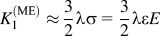 , where λ is the saturation magnetostriction (−33 × 10−6 for bulk Ni8), ε is the thermal expansion coefficient, σ is the force density (per unit area), and E represents the Young modulus. The bulk modulus for Ni is ranging between 177.3 GPaReference Costa-Kramer9 and 330 GPa. In the case of Ni nanowires electrodeposited in polymeric membranes, the difference between the expansion coefficients of the matrix and of nanowires is larger than that in the case of nanowires deposited in alumina templates. These mechanical stresses induce a magnetocrystalline anisotropy.Reference Vonsovskii6, Reference Morrish7 It was concludedReference Dubois, Colin, Duvail and Piraux4 that in the case of Ni nanowires electrodeposited in polymeric (polycarbonate) pores, the temperature dependence of the uniaxial anisotropy is related to the axial elastic strain in the nanowire and membrane.
Packing the nanowires closer and closer enhances the contribution of dipole–dipole interactions.Reference Oropesa, Demand, Piraux, Huynen and Ebels10, Reference Zeng, Zheng, Skomski, Sellmyer, Liu, Menon and Bandyopdadhyay11 At scale lengths below 10 μm,Reference Ounadjela, Ferre, Louail, George, Maurice, Piraux and Dubois12 the dipole–dipole interactions between the nearest nanowires trigger a demagnetizing field, H D, which depends on the spacing between nanowires. Within the mean-field approximation, H D is proportional with the porosity of the template,Reference Zeng, Zheng, Skomski, Sellmyer, Liu, Menon and Bandyopdadhyay11 which is related with the averaged spacing between nanowires.Reference Meier, Doudin and Ansermet13 At high packing density, a collective behavior due to the onset of exchange interactions among nanowires was observed. The array of real nanowires presents complications related to the distribution in the size, shape, and orientation of nanowires.
Magnetic resonance (performed by using electron spin resonance spectroscopy in the ferromagnetic mode) is a powerful tool in the investigation of magnetic propertiesReference Vonsovski14–Reference Brown16 sensitive to shape and magnetocrystalline anisotropies. Within the thermodynamic approach,Reference Zeng, Zheng, Skomski, Sellmyer, Liu, Menon and Bandyopdadhyay11 the position of the resonance line is given by:

or

where W is the free energy density (free energy per volume), H eff is the effective field felt by electrons, ω is the microwave frequency, and λ is the Landau Gilbert damping parameter. The angles θ and φ obey the equilibrium conditions 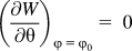 and
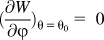 , where φ 0 and θ 0 defines the orientation of the magnetization with respect to the reference axes, at equilibrium. The Ferromagnetic resonance (FMR) data on magnetic nanowires were analyzed within simple models such as the ideal and the perfect nanowire approach. We propose in this article a more general treatment named the real nanowire approach that includes eventual contributions due to magnetocrystalline anisotropy and assumes that the shape anisotropy of nanowires is consistent with an ellipsoid of revolution.
A. The ideal nanowire approach
Some ferromagnetic resonance data on magnetic nanowires were analyzed within the ideal nanowire approximation,Reference Oropesa, Demand, Piraux, Huynen and Ebels10 which assumes that the nanowires define a perfect array of ideal, identical, equally spaced, and parallel cylinders. The distance between nanowires is typically assumed to be sufficiently large to neglect the interactions between them. The magnetic properties of an ideal nanowire are controlled by the shape anisotropy, which is assumed to be a diagonal tensor with N X = N Y = N ⊥ = 2π and N Z = N ‖ = 0. The energy of an ideal magnetic nanowire in an external magnetic field is:

where the first term is the Zeeman contribution and the second reflects the ideal shape anisotropy. If the misalignment of the magnetization from the direction of the external magnetic is negligible, the magnetic spin waves for large external field (N ⊥M 2 < MH) are described by:

The angular dependence of the resonance line position, H RES, for ideal nanowires is:

The relationship (3) allows for a degenerate spin wave if the external magnetic field is parallel to the nanowire, independent of the magnetic wave damping; the corresponding resonance field position is defined by:

In the case of a negligible damping, the shift of the degenerate resonance line position from the expected “paramagnetic” value corresponding to g = 2.0023 reflects the contribution of the shape anisotropy.
B. The perfect nanowire approach
Most FMR data on magnetic nanowires have been analyzed within this approximation.Reference Goglio, Pignard, Radulescu, Piraux, Huinen, Vanhoenacker and Vorst8, Reference Oropesa, Demand, Piraux, Huynen and Ebels10, Reference Ebels, Duvail, Wigen, Piraux, Buda and Ounadjella17 The perfect nanowire approach preserves the ideal shape of the nanowire (NX = NY = N ⊥ = 2π and NZ = N ‖ = 0) and allows for a local uniaxial magnetocrystalline anisotropy, K A, which is responsible for a local field H A = K A/μ 0M S. The free energy of a magnetic nanowire within this approximation is:

H A is a phenomenological local magnetic fieldReference Aharoni1 produced by the magnetocrystalline anisotropy, which acts on electronic spins. At macroscopic scale, it is assumed that spin evolution is controlled by a local field H LOC = H A + N ⊥M that collects both shape and magnetocrystalline anisotropies. Qualitatively, adding the uniaxial magnetocrystalline anisotropy modifies neither the symmetry nor the shape of the expression that describes the angular dependence of ferromagnetic resonance. Formally, the uniaxial magnetocrystalline anisotropy is affecting the shape anisotropy (along the nanowire). The corresponding spin wave for very large external field is:

The angular dependence of the ferromagnetic resonance line is given by:

The degenerate solution is observed if the magnetic field is parallel to the nanowire and leads to

By inspecting the Eqs (2)–(9), it is inferred that the phenomenological local field is solely affecting the shape anisotropy constant, in the plane normal to the wire, as both H A and N ⊥ have the same angular dependence.
This article questions, at both theoretical and experimental levels, the “ideal” and “perfect nanowire” approaches. An improved approximation, which assumes that the nanowires may be represented by ellipsoids and revolution and allows the contribution of both cubic and uniaxial magnetocrystalline anisotropies, up to the second order, is proposed and tested by FMR studies on Ni nanowires.
C. The real nanowire approach
In most cases, additional terms have to be considered in the expression of the magnetic free energy density of a real nanowire. A general expression would include uniaxial magnetocrystalline anisotropies up to the second order and

The expression of the magnetic spin wave in this case is:

where H 1 = H A = K 1/M and H 2U = K 2U/M. The degenerate spin wave for real nanowires is:

The resonance line field for the degenerate spin wave has a simple expression:

In conclusion, if the external magnetic field is parallel to the nanowire, the magnetic spin wave is degenerate and the position of the resonance line has a simple expression. This allows a rapid test for the contribution of different terms to the ferromagnetic resonance line.
II. RESULTS
Ni nanowires with a diameter of 15 nm and a center-to-center separation of 35 nm were produced by electrodeposition within the pores of anodic alumina. The anodic alumina was obtained from a 99.9999 pure Al foil, degreased, etched in nitric acid, and electropolished. The anodization was performed in sulfuric acid under a constant voltage of 10 V using a Pt electrode. The electrodeposition was carried out at 325 K by using an applied voltage of 20 V and 150 Hz and an electrolyte consisting of 0.1 M NiSo4 and 0.1M boric acid. The nanowires have a distorted fcc crystalline structure.Reference Wegrowe, Kelly, Franck, Gilbert and Ansermet18
Electron spin resonance investigations on Fe nanowires were made using a Bruker SP 300 E spectrometer (Bruker BioSpin Corporation, Billerica, MA), operating in X band, equipped with a goniometer that allows the study of the angular dependence of resonance spectra. Hysteresis curves were recorded on the same sample by using an alternating gradient force magnetometer (AGFM).
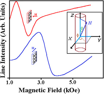
The ferromagnetic resonance spectra of Ni nanowires consist of a broad, and symmetric line, whose position and width is sensitive to the orientation of wires relative to the external magnetic field (Fig. 1). The orientation of the sample, with respect to the external magnetic field, is represented in the inset of Fig. 1. Within the experimental errors, which are below 2°, φ H = 0; hence, the orientation of the sample within the microwave cavity is described by the angle between the external field and the plane of the sample, θ H.
FMR spectra of Ni nanowires. (a) The nanowires are parallel to the static external field. (b) The nanowires are perpendicular to the static external field. The inset gives the orientation of the magnetization and of the external magnetic field, with respect to the sample.

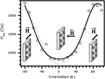
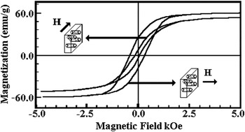
The angular dependence of the resonance line position, for the main line, is shown in Fig. 2. As expected from the sample geometry, the curve is symmetric with respect to θ. The hysteresis curves, obtained on the same sample, for the parallel and perpendicular orientations, are given in Fig. 3.

The hysteresis curves recorded on Ni nanowires (nanowires parallel and respectively perpendicular to the static external field).

III. DISCUSSION
Several authorsReference Skomski, Zeng, Zheng and Sellmyer2, Reference Jaccard, Guittienne, Kelly, Wegrowe and Ansermet19 questioned the ideal nanowire description. The most important terms that are contributing to the free energy density will be discussed below. The free energy of Ni nanowires is dominated by the shape anisotropy. It is assumed an ellipsoidal like shape anisotropy (NXX = NYY = N ⊥ and NZZ = N ‖ ≠ 0). A strong texture was reported in Ni nanowires, based on x-ray diffraction data. As Ni has a cubic symmetry,Reference Morrish7 with K 1U ≅ −K 2U, a contribution due to the magnetocrystalline anisotropy is possible. It is generally assumed that the orientation of these crystallites is random. Averaged cubic magnetocrystalline anisotropies constants, <K 1C> and <K 2C>, may be responsible for K A and K 2U, respectively. This triggers a texture in the orientation of Ni crystallites within the nanowire. An uniaxial magnetocrystalline anisotropy, originating from magnetoelastic effects, due to the difference in the expansion coefficients of alumina template and Ni nanowire, has to be considered. In most cases, the first-and second-order axial magnetocrystalline constants, although correlated with the spatial orientation of nanowires, present a narrow distribution, mainly because the nanowires are not perfectly aligned. This offers an additional reason to use K 1 and K 2U instead of <K 1C> and <K 2C>, respectively.
Collecting these terms, the expression of the free energy density is:

Neglecting (for simplicity) the contribution of second-order terms in the magnetocrystalline anisotropy, the spin wave associated to Eq. (14) is:

The predicted angular dependence of the resonance field in the first-order approximation of real nanowires is:

with

The angular dependence of the resonance line position is represented in Fig. 2. Within the ideal nanowire approximation, the dependence of the resonance field on the orientation of nanowires is rather well described by Eq. (6) (see the bold line in Fig. 2). The best fit of experimental data corresponds to 4πM S = 3.95 ± 0.05 kGauss and to an effective field of 2.95 ± 0.05 kOe (for λ = 0). The effective field is close to the expected value (Heff ≈ 3.0 kOe), typical for a system with g = 2.21.Reference Ounadjela, Ferre, Louail, George, Maurice, Piraux and Dubois12 The estimated value of the magnetization at saturation is significantly lower than the values of the magnetization at saturation for bulk Ni (4πM S = 6.2 ± 0.05 kGauss8) and is to large to be assigned to shape and magnetocrystalline anisotropiesReference Goglio, Pignard, Radulescu, Piraux, Huinen, Vanhoenacker and Vorst8 or dipolar interactions among nanowires.
By fitting the experimental data within the real nanowires approximation, the correlation between the predicted values and the measured ones is slightly improved (see the dotted curve in Fig. 2). Assuming a cylindrical symmetry for Ni nanowires, the parameters corresponding to the best fit were H eff/(1 + λ 2)1/2 = 2.65 ± 0.05 kOe, 4πM S = 5.90 ± 0.05 kOe, <H 1U> ≈ 0. Taking into account that the FMR field corresponds to g = 2.21, the estimated value of the local effective field would be of about 3.0 kOe, instead of the usual 3.3 kOe value (typical for g ≈ 2.00). The damping constant is 0.52, reflecting that the evolution of the magnetization in nanowires has associated a weak viscosity. As discussed by Oropesa et al.,Reference Oropesa, Demand, Piraux, Huynen and Ebels10 the low value of the effective field may be ascribed to the fact that in the perpendicular configuration, the sample is not fully saturated at the resonance field. In this case, the magnetization of the wire is uniform over smaller regions of the nanowire (not over the whole nanowire) that are preferentially oriented along the nanowire. Such a situation has been predicted to occur in real nanowiresReference Sellmyer, Zheng and Skomski20 and would shift the resonance field toward smaller value, affecting the angular dependence of the resonance field. The first-order cubic magnetocrystalline anisotropy is almost zero, reflecting the absence of a crystalline order within the wires.
The estimated value of the magnetization at saturation is smaller than the value reported for bulk Ni (4πM S = 6.2 ± 0.05 kGaussReference Goglio, Pignard, Radulescu, Piraux, Huinen, Vanhoenacker and Vorst8, Reference Ounadjela, Ferre, Louail, George, Maurice, Piraux and Dubois12). This relatively small difference may be due to the deviation from the assumed cylindrical symmetry, to the effect of the uniaxial magnetocrystalline anisotropy, induced by local stresses, and to dipolar interactions among nanowires.
The coefficient of the thermal expansion of alumina is of 8.3 × 10⁻⁶ K−1; the Poisson ratio is equal to 0.22, along Ox, Oy, and Oz axes; and the thermal expansion coefficient of Ni is 13.3 × 10⁻⁶ K−1. The estimated value of the first-order anisotropy constant as the Ni nanowires are relaxing from the deposition temperature to the room temperature is of the order of 102 kGOe, competing with the proper magnetocrystalline anisotropy and justifying the presence of a field along the nanowire. However, only this contribution cannot explain completely the measured shift in the magnetization at saturation.
Dipolar interactions among nanowires may also contribute to the discrepancy between the value of the magnetization at saturation, as derived from FMR experiments and the bulk values. These interactions reduce the demagnetizing term.

where P is the porosity of the template. For the actual Ni nanowires the dipole–dipole interactions are weak (P ≈ 2.4% [5]), and their maximum contribution is of about 125 Oe.
To conclude, both shape anisotropy and magnetocrystalline anisotropy and dipolar interactions between nanowires are contributing to the shift of the resonance line position. Consequently, the position of FMR line is described by:

Solely, the analysis of the angular dependence of resonance line position cannot specify the weight of all these contributions.
The coercive field, as measured by hysteresis curves recorded in magnetic nanowires, for the case in which the external magnetic field is parallel to the nanowire, H C‖, and respectively perpendicular, H C⊥, is of 490 Oe, and 120 Oe, respectively, in good agreement with the data reported elsewhere.Reference Paulus, Luis, Kroll, Schmid and de Longh21 The squareness (M R/M S) is equal to 0.273 in the perpendicular configuration and is increased up to 0.715 in the parallel configuration. These values are slightly higher than the values reported by Cao et al.,Reference Cao, Tie, Xu, Hong and Sang22 reflecting weaker interaction among nanowires. Within the ideal nanowire approach (i.e., assuming a cylinder-like symmetry and neglected all contributions excepting the Zeeman and shape anisotropy), no hysteresis loop is expected to be recorded when the external magnetic field is perpendicular to nanowires.
Both FMR and AGFM prove that the ideal nanowire approximation is rough.Reference Akhiezer, Bar’yakhtar and Peletminskii23–Reference Oropesa, Demand, Piraux, Huynen and Ebels35 The magnetic properties of Ni nanowires are controlled by the shape anisotropy, to which shape and magnetocrystalline contributions act as small perturbations. The main difference between the ideal nanowire and the real nanowire descriptions consists in the replacement of the cylinder-like symmetry with an ellipsoid of rotation symmetry. The detailed expression of the free energy assigned to real nanowires is correct solely for an ideal array of nanowires if the distance between nanowires is large. For simplicity, it was assumed that the array of nanowire is ideal, that is, the nanowires are perfectly parallel and equally spaced. In a real nanowire, these conditions are not fulfilled.
IV. CONCLUSIONS
The angular dependence of the FMR position has been analyzed within a thermodynamic approach. It was noticed that the shape anisotropy is the dominating term and that the contribution of the first-order magnetocrystalline anisotropy is not negligible. The small difference between the value of the magnetization at saturation for bulk Ni and Ni nanowires (as estimated from FMR data) reflects possible contributions due to uniaxial magnetocrystalline anisotropy (originating from magnetostriction effects), deviations from the ideal cylindrical shape, and negligible contributions due to dipolar interactions among nanowires. Both FMR and hysteresis data indicate that the dipole–dipole interaction among nanowires is weak.
ACKNOWLEDGMENTS
The research done at University of Texas Pan American was supported by U.S. Army Research Office (AMSRD-ARL-RO-SI Proposal No. 54498-MS-ISP). The research at University of Nebraska-Lincoln has been supported by NSF-MRSEC program.