Introduction
With the progress of society, the people's living standard has been continuously improved. On the contrary, the negative effects on environment caused by environmental pollution and ecocide through human behavior have been got more and more attention. To solve this problems, degradation of toxic organic pollutants in wastewater or air has received considerable attention over recent years.[ Reference Liu, Pan, Yin, Irvine, Li, Tan, Wormald and Cheng 1 – Reference Zang and Farnood 3 ] Recently, there are many approach to deal with pollutants, such as, biological treatment with enzyme[ Reference He, Qin, Zhang, Yang, Zhang and Yang 4 , Reference Asgher, Bhatti, Ashraf and Legge 5 ] or microorganism,[ Reference Dong, Wang, Li and Chi 6 ] physical treatment of wastewater with flocculating agent[ Reference Di Bella, Giustra and Freni 7 , Reference Suopajärvi, Liimatainen, Hormi and Niinimäki 8 ] and photocatalytic treatment with catalysts.[ Reference Ghodbane, Hamdaoui, Vandamme, Van Durme, Vanraes, Leys and Nikiforov 9 – Reference Jiang, Wang, Wang and Sun 12 ] Because of the biological treatment is strict with its environment, especially with the occurrence of temperature, trivial change should disturb the enzyme or microorganism and make the number different from the reality.[ Reference Khenniche, Favier, Bouzaza, Fourcade, Aissani and Amrane 13 ] Treated wastewater with flocculating agent has a high-efficiency, but the flocculating agent cannot completely remove organic in wastewater.[ Reference Panpa, Sujaridworakun and Jinawath 14 ] However, photocatalytic treatment of organic compounds using semiconductors has proven to be a promising green technology for environmental purification, as they provide an interface with an aqueous medium and induce an advanced oxidation process.[ Reference Kinadjian, Le Bechec, Henrist, Prouzet, Lacombe and Backov 15 – Reference Katsumata, Sakai, Suzuki and Kaneco 17 ]
Semiconductor photocatalysis has been widely investigated for its potential application in environmental protection and solar energy transformation. TiO2 acted as a semiconductor photocatalyst has been obtained a large number of scientific researcher’ attention and got a mass of experimental results over the last 40 decades since Fujishima and Honda discovered TiO2 photochemical electrode in 1972.[ Reference Carey, Lawrence and Tosine 18 ] It is expected to be one of the most valuable photocatalysts due to its oxidative, chemically stable, economical, and non-toxic characteristics. However, TiO2 cannot effectively utilization of solar light, which drives us to make numerous efforts to explore other novel efficient visible-light photocatalysts for the better utilization of solar light through two ways, including coupling other semiconductors with TiO2 [ Reference Fang, Jiang, Wang, Wang, Sun, Wang and Wang 19 – Reference Chen, Chen, Chen, Lu, Zhang, Liu, Wang and Wang 22 ] and exploitation of new non-titania-based visible-light photocatalysts.[ Reference Li, Jiang, Wei, Wang, Chen and Shen 23 – Reference Tang, Jiang, Wei, Li, Wang, Jiang, Chen and Wan 25 ] BiOBr as a significant layer-structured semiconductor has attracted much attention for its visible-light response.[ Reference Wang, Huang, Lin and Yang 26 ] AgBr is widely used as a photocatalyst for the degradation of pollutants due to the narrower band gap and higher visible-light absorption.[ Reference Cui, Jiao, Zhang, Zhou and Peng 27 ] The two materials have matching energy band structures, according to the data reported in the literature, and which can effectively separate photogenerated electrons and holes to achieve enhanced photoactivity relative to that of either AgBr or BiOBr.[ Reference Kong, Jiang, Lai, Nicholls, Xiao, Jones and Edwards 28 , Reference Lu, Kong, Jiang, Lai, Xiao and Edwards 29 ]
On the other hand, due to their high surface energy, the photocatalysts with nanostructure tend to form agglomerates, which could lead to the decrease their active sites and catalytic activity. Furthermore, these catalysts are usually recycled by tedious and time-consuming processes, including centrifugation and re-dispersion cycles, thus hampering the reusability of recycled catalysts in aqueous solutions.[ Reference Liu, Jiang, Li, Chen, Huang, Jiang, Du and Chen 30 ] Nanofibrous materials enjoy the priority over the other materials due to their attractive features of structural characteristics, such as high porosity and interconnectivity, which are beneficial to the diffusion of substrate or product molecules onto/from active sites.[ Reference Liu, Zhang, Li and Zhang 31 , Reference Huang, Wang, Tian and Zhang 32 ] Therefore, intensive attentions have been attracted for supporting highly active catalysts like noble metal nanoparticles onto the electrospinning nanofibrous membranes.[ Reference Liu, Jiang, Li, Chen, Huang, Jiang, Du and Chen 30 – Reference Zhang, Shao, Mu, Zhang, Guo, Zhang and Liu 33 ]
In this paper, a green and environmentally friendly electroless plating technique has been provided to prepare the composite nanofibers materials as photocatalysts degradation of rhodamine-B (RhB) and reduction of p-nitrophenol (p-NP) under the visible-light irradiation and at room temperature. Although the similar composition of nanofibers have been prepared by our group,[ Reference Jiang, Wei, Chen, Du, Li, Liu, Huang and Chen 34 ] the composite carbon nanofibers (CNFs) with hierarchical nanostructures of BiOBr/AgBr were obtained by a simplified process, including adding the certain amount of BiOBr/AgBr precursors into the spinning solution and following electrospinning and carbonization treatments. The as-prepared composite CNFs exhibited highly photocatalytic activities for degradation of RhB and reduction of p-NP under the visible-light irradiation and at room temperature. Furthermore, the as-prepared composite CNFs showed the favor separation, recovery, and cyclic utilization properties.
Experimental
Materials
Polyacrylonitrile (PAN, M w = 150,000), N, N′-dimethylformamide (DMF, AR), bismuth nitrate pentahydrate [Bi(NO3)3•5H2O, AR], silver nitrate (AgNO3, AR), potassium bromide (KBr, AR), and hexadecyl trimethyl ammonium bromide (CTAB, AR) were purchased from aladdin Co. Ltd. (China) and all other reagents were used as received without further purification. The flower-like BiOBr microsphere photocaqtalysts were prepared by a reported method.[ Reference Zhang, Shi, Lin, Chen, Gao, Huang, Ding and Tang 35 ]
Fabrication of composite CNFs
The electrospinning machine consisted of three major components: an injection pump, a high-voltage supply, and a receptor. In the typical procedure, firstly, PAN was homogeneous dispersed in DMF by stirring for several hours to obtain a homogeneous solution with a concentration of 8 wt.%. Subsequently, about 10 mL of the PAN/DMF solution was transferred in a 10 mL injection syringe with a capillary tip having a 2.5 cm length and an outer diameter of 0.7 mm. The injection syringe was laid in an injection pump that set a solution injection speed of 0.12 mm/h. The receptor was a grounded metallic rotating receptor which covered with aluminum foil and was set rotated at 500 rpm. There is a distance about 10 cm between the needle and receptor. The PAN nanofibers were collected on the aluminum foil by electrospinning from a syringe at an applied electric positive voltage of +15 kV and the negative voltage of −2.0 kV. Then, the electrostatic spinning PAN nanofibers were transferred to a tube furnace calcine with N2 protection. The samples were firstly heated at 100 °C for 1 h to remove the PAN solvent and moisture. Then, the temperature was increased to 150 °C for 1 h and 500 °C for 2 h and 800 °C for 4 h to carbonize. The heating rate was controlled at 4 °C per minute. After cooling, the carbonize nanofibers (CNFs) could be obtained. BiOBr/CNFs and BiOBr/AgBr/CNFs were obtained as the same method except adding certain amount of BiOBr precursor and BiOBr/AgBr precursor into the PAN/DMF solution before eletrospinning. The BiOBr precursor is composed of 250 mg (0.5 mM) Bi(NO3)3•5H2O and 60 mg (0.5 mM) KBr. The BiOBr/AgBr precursor is prepared by adding 250 mg (0.5 mM) Bi(NO3)3•5H2O, 5 mg (0.03 mM) AgNO3, and 63 mg (0.53 mM) KBr into PAN/DMF solution.
Charaterization
The microstructures and crystal phase of the as-prepared samples were analyzed with a Siemens Diffraktometer D5000 x-ray diffractometer (XRD) with Cu K α radiation source at 35 kV, with a scan rate of 10° s−1 in the 2θ range of 5°–80°. The ULTRA-55 field emission scanning electron microscopy (FE-SEM) at an accelerating voltage of 10 kV and JSM-2100 transmission electron microscopy (TEM) were used to characterize the morphologies of the as-prepared samples. The Brunauer–Emmet–Teller (BET) specific surface area was measured using a specific surface and pore size analysis instrument (3H-2000PS1/2 static volume method, China). The UV–vis diffuse reflectance spectra were obtained for the dry-pressed disc samples using a UV–vis spectrometer (U-3010, Hitachi). X-ray photoelectron spectroscopy (XPS) data were obtained with an ESCALab220i-XL electron spectrometer from VG Scientific using 300 W Al K α radiation. The base pressure was about 3 × 10⁻⁹ mbar. The binding energies were referenced to the C1s line at 284.6 eV from adventitious carbon.
Measurement of photocatalytic activity
The photocatalytic activity of the CNFs was investigated by the photodegradation of RhB and p-NP. The photodegradation experiments were implement in the photodynamic reaction chamber. The optical source was 500 W high-pressure Xenon lamp and the lamp was equipped with ultraviolet cut-off filter to provide visible light (λ ≥ 400 nm) (model BL-GHX-V, Shanghai Bilon Instruments Factory, China).
For the photocatalytic degradation of organics, a piece of CNF membranes (10 × 10 cm2) were dipped into 50 mL organics aqueous solution with a concentration of 10 mg/L for RhB or 1.70 mM/L for p-NP. Before irradiation, the suspensions were stirred in the dark for 1 h to ensure the adsorption–desorption equilibrium. The concentration of organics was measured by JASCO V-570 UV–vis–NIR spectrophotometer (Japan). For the comparison, a blank experiment (without any catalysts) was carried out for indicating the adsorption of organics under the same conditions. The trapping experiments for detecting the active species during photocatalytic reactivity was similar to the photocatalytic activity test above besides adding 1.0 mM of quenchers to solution before light irradiation.[ Reference Jiang, Li, Wei, Wang, Tang and Chen 36 ]
Results and discussion
The morphology and structure of the hybrid CNFs were firstly characterized by field emission scanning electron microscopy (FE-SEM). Figure 1(a) shows the SEM image of pure CNFs with 200–300 nm in diameter. And the smooth surface can be observed in the magnification SEM image, as shown inset in Fig. 1(a). After addition of BiOBr precursor into the spinning solution, the rough surface of the prepared hybrid carbon nanofibers (BiOBr/CNFs) can be founded, as shown in Fig. 1(b). And the large amount of nanoparticles with size about 10–25 nm and irregular shape on the surface of hybrid CNFs can be observed, as shown inset in Fig. 1(b). Interesting, further addition of AgBr into the spinning solution, the rough surface of the hybrid carbon nanofibers (BiOBr/AgBr/CNFs) still can be founded, as shown in Fig. 1(c). However, the porous structure on the surface can be formed [inset in Fig. 1(c)]. This observation possible suggests that the formation of porous structure will be beneficial to create more active sites for catalytic reaction. A typical TEM image of BiOBr/AgBr/CNFs is shown in Fig. 1(d), which further confirms that the presence of porous structure on the surface of hybrid CNFs.
SEM images of carbon CNFs (a); hybrid carbon nanofibers (BiOBr/CNFs) (b); BiOBr/AgBr/CNFs (c); and TEM image of BiOBr/AgBr/CNFs (d).

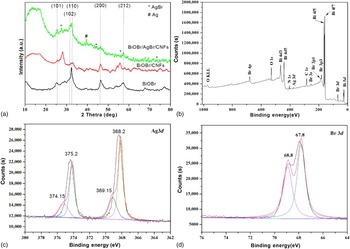
The crystallographic structure of the composite nanofibers was further confirmed by powder x-ray diffraction (XRD) analysis. Figure 2(a) shows the XRD patterns of the as-prepared samples. It can be found that the pristine CFs exhibit a broad peak located between 10° and 20° assigned as the d 002 layers, representing the presence of integral graphite crystal structure.[ Reference Jiang, Li, Wei, Wang, Tang and Chen 36 , Reference Jiang, Li, Wei, Wang, Jiang, Du and Chen 37 ] No detectable dopant-related peaks can be observed in BiOBr/CNFs except the typical tetragonal structure of BiOBr crystal (JCPDS No. 73-2061). The relatively weak peaks at 2θ = 26.7°, 44.4°, 55.1° and 73.3°, indexed to AgBr (111), (220), (222), and (420) plane reflections, respectively (JCPDS: 06-0438).[ Reference Dong, Tian, Zhang, Wang, Tao, Bao, Yang and Zeng 38 ] The peak around the scanning angle 2θ = 38.12°, corresponding to the cubic phase of Ag (111) (JCPDS: 04-0783), which implies the metallic Ag0 has been produced after heat treatment.[ Reference Tian, Wang, Dong, Bao, Yang and Zhang 39 ]
XRD patterns of BiOBr, BiOBr/CNFs and BiOBr/AgBr/CNFs (a); XPS spectrum of the as-prepared BiOBr/AgBr/CNFs (b); high-resolution XPS spectra of Ag 3d (c); and Br 3d (d).

XPS analysis can provide a valuable insight into the surface structure of hybrid carbon nanofibers (BiOBr/AgBr/CNFs). The XPS survey spectrum of the photocatalyst exhibit prominent peaks of carbon, oxygen, bromine, bismuth, and relatively feeble peaks of silver, as shown in Fig. 2(b). To investigate the Ag valence states, the high-resolution XPS spectrum of Ag 3d on BiOBr/AgBr/CNFs was measured. As shown in Fig. 2(c), in the high-resolution XPS spectrum of Ag 3d, can be observed two peaks at binding energies of 374.4 and 368.4 eV, corresponding to Ag 3d3/2 and Ag 3d5/2, respectively.[ Reference Prieto, Nistor, Nouneh, Oyama, Abd-Lefdil and Díaz 40 , Reference Feng, Wang, Zheng, Zhang, Fan, Liu, Amoureux and Deng 41 ] The Ag 3d3/2 peak is further divided into two different peaks at 374.15 and 375.2 eV, and the Ag 3d5/2 peak is divided into two different peaks at 368.15 and 369.15 eV, respectively. The peaks at 375.2 and 369.15 eV are attributed to metal Ag0, and the peaks at 374.15 and 368.15 eV are attributed to Ag+ of AgBr.[ Reference Jinfeng and Tao 42 ] The peaks at 68.8 and 67.8 eV are usually assigned to the Br− [Fig. 2(d)].[ Reference Liu, Su, Chen, Jin and Wang 43 ] Nitrogen adsorption–desorption isotherm curves were carried out to investigate the surface area of the samples. The BiOBr/AgBr/CNFs possesses the highest specific surface area at 131.44 m2/g, compared with that at 98.25 and 9.20 m2/g for BiOBr/CNFs and CNFs samples.
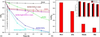
The photocatalytic of the hybrid CNFs samples is firstly evaluated by degradation of RhB (10 mg/mL) under the visible-light irradiation (λ ≧ 400 nm) and at room temperature (T = 300 K). For the comparison, a blank experiment (no addition any catalysts) is firstly carried out for indicating the self-photodegradation of RhB. As shown in Fig. 3(a), it can be found that RhB self-photodegradation is almost negligible under light irradiation without any catalysts. Compared with the blank experiment, the decolorization rate of RhB can be accelerated in the presence of pure CNFs within first 1 h due to the adsorption and the further adsorption of RhB is no prominent change for prolonging immersion time. However, the decolorization rate of RhB for BiOBr/CNFs or BiOBr/AgBr/CNFs in the dark is slightly higher than that of CNFs. It can be contributed to the higher specific surface area of hybrids compared with that of CNFs. The decolorization change is very slight after the hybrids immersed in RhB solution for 1 h due to the equilibrium of adsorption–desorption. The decolorization rate of RhB can be further accelerated in the presence of BiOBr as the visible-light photocatalyst. And more than 50% of RhB can be removed after 2 h. There is no doubt here that photocatalysis plays an important role to decolor RhB besides photolysis and adsorption. The CNFs containing of BiOBr or BiOBr/AgBr enlarge their specific surface areas, thus increasing the RhB adsorption capacity as well. Meanwhile, the pre-enriched RhB molecules can be excited by light, and then the photoinduced electrons inject into the conduction band, triggering the photodegradation reactions.[ Reference Jiang, Li, Wei, Wang, Tang and Chen 36 , Reference Liu, Yang, Jiao, Tian, Wang and Jiang 44 ] As shown in Fig. 3(a), almost all of RhB can be removed in the presence of BiOBr/CNFs or BiOBr/AgBr/CNFs. The higher decolorization rate can be observed for BiOBr/AgBr/CNFs as catalyst due to the synergistic reaction between the photocatalysts and special porous structure of hybrid CNFs.
Photocatalytic degradation of RhB over various products (a) and trapping experiments for detecting of active species experiment during the photocatalytic degradation of RhB reaction by the addition of 1.0 mM IPA, TEOA, or BQ (b, inset shows cycling runs for the photodegradation of RhB over the BiOBr/CNFs and BiOBr/AgBr/CNFs).

For investigation of the active species for the photocatalytic activity of hybrid CNFs, the trapping experiments for detecting the hydroxyl radicals (•OH), the superoxide radical (O2•−) and holes (h+) are investigated by adding 1.0 mM isopropyl alcohol (IPA, a quencher of •OH), p-benzoquinone (BQ, a quencher of O2•−) and triethanolamine (TEOA, a quencher of h+) before light irradiation. It can be found that the photocatalytic decoloration of RhB is declined slightly by the addition of IPA. And addition of BQ or TEOA into the reaction system, the decolorization rate of RhB were decelerated significantly. Therefore, it can be concluded that O2•− and h+ are the main active species for degradation of RhB under visible-light irradiation, rather than •OH, as shown in Fig. 3(b). The result is consistence with our early report.[ Reference Jiang, Li, Wei, Wang, Tang and Chen 36 ] More important is the negligible loss of catalytic activity even after the fifth cycle. It indicates the high stability, including favor separation, recovery, and cyclic utilization properties, of the resultant composite nanofibers, as shown inset in Fig. 3(b).
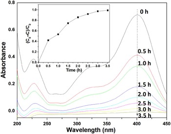
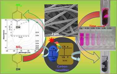
The catalytic properties of BiOBr/CNFs and BiOBr/AgBr/CNFs were further evaluated photocatalytic conversion of p-NP to p-aminophenol (p-AP) as a model reaction. As shown in Fig. 4, the p-NP in aqueous solution shows a distinct spectral profile with a maximum absorption peak at 400 nm. A piece of BiOBr/AgBr/CNFs membranes (~0.01 g) were immersed into 50 mL p-NP (C 0 = 1.70 mM/L) solution. And no co-reducing agent (for example, NaBH4) has been used in this system compared with other reduction of p-NP systems.[ Reference Chen, Jiang, Li, Liu, Huang, Jiang and Du 45 , Reference Méndez, Vargas, Borrás, Blanco, Mostany and Scharifker 46 ] The catalytic activity of the prepared hybrid composite nanofibrous membranes was evaluated by photometrically monitoring the reduction of p-NP to p-AP. Figure. 4 shows the profiles of absorbance at 400 nm against reaction time. More than 99% of p-NP can be reduced within 3.5 h for three products, as shown inset in Fig. 4. The color of solution changes from dark yellow to colorless as well. However, the intensity change of maximum absorption peak at 400 nm is almost negligible under light irradiation without the presence of BiOBr/AgBr/CNFs membranes. There is no doubt here that hybrid CNFs play an important role to conversion of p-NP. The possible reason for reduction of p-NP with absence of co-reducing agent is the O2•− as a reducing active specie to produce under the light irradiation.
UV–vis adsorption spectra of the reduction of p-NP by BiOBr/AgBr/CNFs composite nanofibrous membranes [inset shows plots of (C 0–C)/C 0] versus time using BiOBr/AgBr/CNFs composite nanofibrous membranes as catalyst).

Conclusion
In this paper, the composite CNFs with hierarchical nanostructures of BiOBr/AgBr were obtained by a simplified process, including adding the certain amount of BiOBr/AgBr precursors into the spinning solution and following electrospinning and carbonization treatments. The as-prepared composite CNFs exhibited a highly photocatalytic activitie for degradation of RhB under the visible-light irradiation and at room temperature. Furthermore, the as-prepared composite CNFs also could be used to reduce p-NP without presence of any co-reducing agent. The resultant hybrid carbon composite membranes offer the significant advantages, such as low dosage, high catalytic activity, easy recycling, and excellent stability.
Acknowledgments
This work was financially supported by the National Natural Science Foundation of China (grant numbers 51373155 and 51133006) and “521 Talents Training Plan” in Zhejiang Sci-Tech University (ZSTU).