


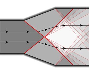
1 Introduction
In supersonic confined flows, shock waves are bound to interact with boundaries such as solid walls and material interfaces or with other recognisable flow features such as acoustic wave fans, shear layers and, of course, other shocks. From the macroscopic point of view, the approximation of thin layers as surfaces of discontinuity within the fluid is often reasonable and advantageous. It is the case, for example, of shock waves of moderate or high intensity in high-Reynolds-number flows and away from boundary layers, of material interfaces and of sharp shear layers. Within this approximation – compatible with the inviscid limit of the governing equations of fluid dynamics – the interaction of two such fronts occurs along singular lines. In the simpler context of two-dimensional planar flows, where discontinuities are represented by lines, the interaction of shock waves thus occurs at a point. The flow field in the neighbourhood of the interaction point has been the focus of numerous studies, starting with the early work of Courant & Friedrichs (Reference Courant and Friedrichs1948), Landau and D’yakov (reported by Landau & Lifshitz (Reference Landau and Lifshitz1987)), Guderley (Reference Guderley1962) and Edney (Reference Edney1968), among others. Later on, a comprehensive description and classification of the steady-state wave patterns near the interaction point was formulated by Glimm et al. (Reference Glimm, Klingenberg, McBryan, Plohr, Sharp and Yaniv1985), who also introduced the term ‘node’ to indicate the point of intersection of discontinuity curves. In the analysis of Glimm et al. (Reference Glimm, Klingenberg, McBryan, Plohr, Sharp and Yaniv1985) and in related studies (e.g. Grove Reference Grove1989), the node pattern is examined by analogy with the Riemann problem for one-dimensional unsteady flow.
The possibility of exploiting such an approach follows from two main observations. Firstly, the equations for two-dimensional supersonic steady flow and one-dimensional unsteady flow are largely equivalent, specifically: (i) the two systems are both associated with two acoustic wave families and a linearly degenerate one, (ii) the streamlines correspond to the time-like direction, and (iii) the flow direction and Mach angles in two dimensions play the role of the velocity and speed of sound in one dimension, respectively (see also Menikoff (Reference Menikoff1989)). Secondly, it is necessary that the interacting waves provide scale-invariant, supersonic initial data (in terms of time-like direction) for the Riemann problem. This requirement implies, on the one hand, that the trajectories of the incoming waves in the node are straight (or equivalently that the focus is on the immediate vicinity of the node, where the interacting waves can be approximated by straight lines separating wedge-shaped regions) and, on the other hand, that the downstream states remain supersonic. When these conditions are satisfied, the outcome of the shock interaction is determined, as in the one-dimensional case, by the intersection of the acoustic wave curves (in the pressure–flow direction diagram, rather than in the pressure–velocity plane). This is the classical method of wave curves.
The analysis of the shape of wave curves in two-dimensional steady flows, however, brings to light important differences from the one-dimensional unsteady case. The wave curves in two dimensions include states that are subsonic; this is related to the fact that, across the shock, the flow may be transonic and implies that for some cases a Riemann problem cannot be established (note that this does not necessarily mean that a steady-state scale-invariant solution can be constructed; see e.g. the degenerate cross-node configuration in Henderson & Menikoff (Reference Henderson and Menikoff1998)). Moreover, the two-dimensional wave curves are bounded and may fail to intersect. The non-existence of the solution signals that the analysis of the bifurcation or scattering of the node necessarily requires unsteady flow considerations (see e.g. Glimm & Sharp Reference Glimm and Sharp1986; Hornung Reference Hornung1986; Grove & Menikoff Reference Grove and Menikoff1990). At the same time, non-uniqueness of some two-dimensional steady Riemann problems is a well-known feature (e.g. Henderson & Atkinson Reference Henderson and Atkinson1976), the most relevant example being the parameter domain where both regular and Mach reflections are possible.
The theory developed in the references mentioned above is based on the assumption (either explicit or implicit) that the acoustic wave families are genuinely nonlinear, thus generating compression shock waves and centred expansion fans in a scale-invariant flow. The genuine nonlinearity of the acoustic wave families is formally expressed (Menikoff & Plohr Reference Menikoff and Plohr1989; Vimercati, Kluwick & Guardone Reference Vimercati, Kluwick and Guardone2018) by the condition  $\unicode[STIX]{x1D6E4}>0$, where
 $$\begin{eqnarray}\unicode[STIX]{x1D6E4}=\frac{v^{3}}{2c^{2}}\left(\frac{\unicode[STIX]{x2202}^{2}P}{\unicode[STIX]{x2202}v^{2}}\right)_{s}\end{eqnarray}$$
is the fundamental derivative of gas dynamics (Thompson Reference Thompson1971), in which  $P$ is the pressure,
 $v$ is the specific volume,
 $c$ is the speed of sound and
 $s$ is the specific entropy. If
 $\unicode[STIX]{x1D6E4}<0$, unconventional phenomena such as expansion shocks, compression fans, shock waves with upstream or downstream sonic state and composite waves can be formed (see also Thompson & Lambrakis Reference Thompson and Lambrakis1973; Cramer & Kluwick Reference Cramer and Kluwick1984; Cramer & Sen Reference Cramer and Sen1987; Cramer Reference Cramer1989b; Menikoff & Plohr Reference Menikoff and Plohr1989; Kluwick Reference Kluwick, Ben-Dor, Igra and Elperin2001). For this reason, gas dynamics associated with states featuring negative or mixed values of the fundamental derivative is known as non-classical gas dynamics. A distinguishing feature of the non-classical gas-dynamic regime is that a given supersonic state can be connected with as many as three different states by means of the Rankine–Hugoniot relations (see e.g. Thompson Reference Thompson1988). The theory of admissible shock waves in the non-classical gas-dynamic regime is well established and enables the selection of the physically relevant solutions of the Rankine–Hugoniot relations; detailed discussions can be found for example in Kluwick (Reference Kluwick, Ben-Dor, Igra and Elperin2001) and Zamfirescu, Guardone & Colonna (Reference Zamfirescu, Guardone and Colonna2008).
Thermodynamics requires  $\unicode[STIX]{x1D6E4}$ to be positive in the dilute-gas limit (for a gas with constant specific heats). Indeed, for a perfect gas the fundamental derivative is given by
 $\unicode[STIX]{x1D6E4}=(\unicode[STIX]{x1D6FE}+1)/2>1$, where
 $\unicode[STIX]{x1D6FE}$ is the ratio of the specific heats. However, negative values of
 $\unicode[STIX]{x1D6E4}$ can in principle be observed in the close proximity to the liquid–vapour saturation curve and critical point (Nannan, Guardone & Colonna Reference Nannan, Guardone and Colonna2014; Nannan et al. Reference Nannan, Sirianni, Mathijssen, Guardone and Colonna2016). In addition, a family of highly molecularly complex fluids, commonly referred to as Bethe–Zel’dovich–Thompson (BZT) fluids, is expected to exhibit negative nonlinearity in a finite vapour-phase thermodynamic region (also known as BZT region) neighbouring the saturation curve. According to modern and most accurate thermodynamic models, candidate BZT fluids are believed to belong to the classes of hydrocarbons, fluorocarbons and siloxanes (Lambrakis & Thompson Reference Lambrakis and Thompson1972; Cramer Reference Cramer1989a; Colonna, Guardone & Nannan Reference Colonna, Guardone and Nannan2007).
Qualitative sketch illustrating the configuration of the incoming waves for different nodes. The undisturbed supersonic flow is aligned with the  $x$-axis (from left to right). An outgoing wave can disappear for specific incoming shock conditions or if the flow downstream of an incoming shock is subsonic.

In the present work, a step towards the understanding of the shock-interaction mechanisms in non-classical gas dynamics is performed. The focus is on single-phase flows of BZT fluids. Retaining the same approach as in previous investigations (in particular, Glimm et al. (Reference Glimm, Klingenberg, McBryan, Plohr, Sharp and Yaniv1985), Grove (Reference Grove1989) and Grove & Menikoff (Reference Grove and Menikoff1990)), the graphical analysis of wave curves in the pressure–flow direction diagram is applied to determine the steady-state node patterns corresponding to different configurations of interacting discontinuities. With reference to figure 1, these are the crossing of shock waves travelling in opposite directions (cross node), the overtaking of shocks travelling in the same direction (overtake node), the splitting of shock waves (Mach node) and the regular refraction of shocks through a contact discontinuity (refraction node). To this end, we take advantage of the theory of non-classical wave curves developed by Vimercati et al. (Reference Vimercati, Kluwick and Guardone2018). Two new features need to be considered in non-classical gas dynamics: firstly, the possibility that one or more waves generated by the interaction are non-classical (for example, a composite wave); secondly, one or more of the interacting waves may be an expansion shock.
The primary goal of this investigation is to illustrate how non-classical shock interactions arise. To this end, the van der Waals gas model of a BZT fluid is employed. The question arises, then, whether the computed configurations are specific to the van der Waals gas used in this study or of more general nature. A complete classification of each realisable node pattern, together with the precise definition of the boundaries, in the parameter space associated with the incident waves, inside which a specific configuration is observed, are beyond the scope of this analysis. Nevertheless, it is expected that qualitatively similar node patterns can be obtained from other thermodynamic models of BZT fluids. This result is suggested by the qualitative correspondence, among diverse thermodynamic models of BZT fluids, of the domain of upstream-state parameters leading to the different wave-curve configurations (Vimercati et al. Reference Vimercati, Kluwick and Guardone2018) and it is confirmed by further computations using state-of-the-art thermodynamic models present here. More generally, such an approach is fundamentally motivated by the similar curvature properties of the shock adiabats and has been successfully employed in various studies concerning BZT fluids, from the aforementioned two-dimensional steady scale-invariant flow (Vimercati et al. Reference Vimercati, Kluwick and Guardone2018) to unsteady shock propagation in one and two dimensions (Alferez & Touber Reference Alferez and Touber2017; Touber & Alferez Reference Touber and Alferez2019).
The structure of the present work is the following. Section 2 provides the necessary background for the inspection of the node patterns in non-classical gas dynamics. Sections 3–6 are devoted to the analysis of the different types of node, namely the cross node, overtake node, Mach node and refraction node, respectively. For each node, both compression and expansion incident shocks are considered. To illustrate shock interactions in non-classical gas dynamics, the van der Waals gas model is used; in § 7 are reported results of accurate thermodynamic models for selected fluids. Finally, § 8 gives the concluding remarks.
2 Governing equations and method of solution
We consider a two-dimensional, steady, single-phase flow in which the effects of viscosity, thermal conduction, chemical reactions and other non-equilibrium effects are limited to layers of negligible thickness and can all be disregarded. Under the further assumption of negligible body forces, the balance equations of mass, momentum and energy, written in integral form for a control volume  $\unicode[STIX]{x1D6FA}$ with boundary
 $\unicode[STIX]{x2202}\unicode[STIX]{x1D6FA}$ and unit outer-pointing normal
 $\boldsymbol{n}$, are
 $$\begin{eqnarray}\oint _{\unicode[STIX]{x2202}\unicode[STIX]{x1D6FA}}\boldsymbol{F}\boldsymbol{\cdot }\boldsymbol{n}\,\text{d}S=0,\end{eqnarray}$$
where
 $$\begin{eqnarray}\boldsymbol{F}=(\unicode[STIX]{x1D70C}\boldsymbol{u},\unicode[STIX]{x1D70C}\boldsymbol{u}\otimes \boldsymbol{u}+P\unicode[STIX]{x1D644},\unicode[STIX]{x1D70C}\boldsymbol{u}h^{t}),\end{eqnarray}$$
is the flux density, in which  $\unicode[STIX]{x1D70C}$ is the density,
 $\boldsymbol{u}$ is the particle velocity,
 $h^{t}=e+\Vert \boldsymbol{u}\Vert ^{2}/2$ is the specific total enthalpy,
 $e$ is the specific internal energy and
 $\unicode[STIX]{x1D644}$ is the unit tensor. Equations (2.1) are equivalent to the Euler equations at points where the flow variables are smooth and to the Rankine–Hugoniot relations at points of jump discontinuities (see e.g. Thompson Reference Thompson1988). The specification of the equation of state
 $P(e,\unicode[STIX]{x1D70C})$ completes the equations; it is assumed that this relation derives from a consistent fundamental relation
 $s(e,v)$, see e.g. Callen (Reference Callen1985).
2.1 Two-dimensional steady scale-invariant flow
The interaction of shock waves with other shocks or contact discontinuities occurs at singularity points called nodes. The flow field in the immediate vicinity of these singularities is properly described in terms of elementary waves (see Glimm et al. Reference Glimm, Klingenberg, McBryan, Plohr, Sharp and Yaniv1985; Glimm & Sharp Reference Glimm and Sharp1986). In two space dimensions, an elementary wave is a steady, scale-invariant solution of equation (2.1). As such, it consists of uniform states separated by waves propagating along rays (straight lines) centred on the node. It is convenient to assign a direction to every wave, based on the tangential velocity along the shock or contact front and each acoustic wave in a centred fan: if this points towards the node, the wave is incoming, otherwise the wave is outgoing (Henderson & Menikoff Reference Henderson and Menikoff1998). It is customary to regard the incoming waves as data, while the outgoing waves are to be determined.
Before addressing the structure of elementary waves in non-classical gas dynamics, it is necessary to summarise the properties of scale-invariant waves in steady planar flows. The restriction of the Euler equations to scale-invariant flows in two space dimensions yields a system of four ordinary differential equations for the independent variable  $x/y$, in a Cartesian
 $(x,y)$ coordinate system centred on the node, or equivalently for the angular coordinate, in a polar coordinate system. The imposition of scale invariance thus leads to the elimination of the radial derivatives. Similarly, the Rankine–Hugoniot relations are satisfied across each ray carrying a jump discontinuity.
As is well known (see e.g. Godlewski & Raviart Reference Godlewski and Raviart2013), the system of equations so obtained is non-strictly hyperbolic for supersonic flow  $M>1$ (
 $M=\Vert \boldsymbol{u}\Vert /c$ is the flow Mach number) with three characteristic families. The acoustic families propagate with slope
 $\unicode[STIX]{x1D717}-\unicode[STIX]{x1D707}$ (right-running acoustic waves) or
 $\unicode[STIX]{x1D717}+\unicode[STIX]{x1D707}$ (left-running acoustic waves), where
 $\unicode[STIX]{x1D717}$ is the local streamline slope (positive if anticlockwise) and
 $\unicode[STIX]{x1D707}=\sin ^{-1}(1/M)$ is the Mach angle. These characteristic fields are non-degenerate, except at isolated points corresponding to
 $\unicode[STIX]{x1D6E4}=0$. The remaining characteristic family is directed along the particle paths and is a linearly degenerate mode of double multiplicity.
Besides the trivial solution corresponding to a completely uniform flow, two constant-state circular sectors about the node can be separated by one of the following waves:
(i) Simple waves or Prandtl–Meyer waves. These are centred fans of acoustic waves. By definition, the Mach number normal to each acoustic wave in the fan is equal to one (Thompson Reference Thompson1988). A simple wave expands the flow if
 $\unicode[STIX]{x1D6E4}>0$ and compresses the flow if $\unicode[STIX]{x1D6E4}<0$. A simple wave breaks down at degenerate points if $\unicode[STIX]{x1D6E4}=0$.
(ii) Shock waves – discontinuities in the acoustic wave families. Physically admissible shocks must satisfy certain admissibility criteria, among which are the entropy-increase condition, the speed ordering relation on the Mach number normal to the shock front and the existence of a one-dimensional thermoviscous profile (Kluwick Reference Kluwick, Ben-Dor, Igra and Elperin2001). Admissible shock waves compress the flow in positive-
$\unicode[STIX]{x1D6E4}$ fluids, but in the neighbourhood of the $\unicode[STIX]{x1D6E4}<0$ region of BZT fluids, expansion shocks are admissible. Shock waves crossing the transitional curve $\unicode[STIX]{x1D6E4}=0$ may feature unit normal Mach number in the pre-shock state (pre-sonic shock), post-shock state (post-sonic shock) or both states (double-sonic shock). These are called sonic shocks.(iii) Composite waves. A sonic shock can be placed next to a simple wave of the same characteristic family to form a composite wave. Composite waves naturally arise in the presence of degenerate points
$\unicode[STIX]{x1D6E4}=0$ due to folding of acoustic waves or violation of shock admissibility criteria (Menikoff & Plohr Reference Menikoff and Plohr1989).(iv) Contact discontinuities – discontinuous waves of the linearly degenerate characteristic family. The pressure and flow direction are constant across the contact, while the entropy and velocity magnitude can experience jumps.


Owing to their general geometrical property of forming a non-zero angle with respect to the local flow direction, the waves of the acoustic families (simple waves, shock waves and composite waves) are called here oblique waves.
The separation of the propagation speed (slope) between waves of distinct characteristic families, along with the requirement for  $2\unicode[STIX]{x03C0}$ periodicity, implies that an elementary wave includes at most one incoming wave of each family and at most one outgoing wave of each family. Thus two incoming oblique waves are allowed, one left-running and one right-running, separated by a contact discontinuity, which necessarily coincides with the streamline entering the node. The same considerations apply for the outgoing waves.
2.2 Classification of nodes
Taking into account the physical meaning of the wave interaction, we shall limit our considerations to configurations containing at most two incoming rays. Other configurations are indeed geometrically irregular (Sanderson Reference Sanderson2004), in the sense that a slight geometrical perturbation of one of the incoming rays would break the single-node interaction pattern into multiple nodes. This requirement also excludes the case of incoming wave fans centred on the node.
Having restricted the analysis to configurations containing at most two incoming rays leaves us with a limited number of possible nodes. Following Glimm et al. (Reference Glimm, Klingenberg, McBryan, Plohr, Sharp and Yaniv1985), the node pattern can be classified on the basis of the incoming waves as follows (cf. figure 1):
(i) Cross node: collision of two oblique shocks of opposite families.
(ii) Overtake node: collision of two oblique shocks of the same family.
(iii) Mach node: splitting of an incoming oblique shock (special case of cross or overtake node in which an incoming shock disappears).
(iv) Refraction node: regular refraction of an oblique shock through a contact discontinuity.
When the flow downstream of the incident shocks is supersonic, a supersonic steady-state Riemann problem is established, in which the data are provided by the states behind the incident waves (see also Menikoff Reference Menikoff1989). Thus, three outgoing waves are expected at the node, namely two oblique waves with a slip line in between. An outgoing oblique wave can disappear (degenerate node) for special deflection angles of the incident shocks, or more commonly if the flow downstream of an incident shock is subsonic. In this work, the analysis of shock interactions is limited to configurations in which the flow downstream of the incident shocks is supersonic.
2.3 Wave curves for two-dimensional steady flow
In the context of two-dimensional, steady, scale-invariant flows, a wave curve of an acoustic family is by definition the set of states connected to a given upstream supersonic state by oblique waves. The importance of wave curves in the study of elementary waves is evident: since the pressure and flow direction are constant across contact discontinuities, then, given the incoming waves at the node, the task of determining the outgoing waves translates into that of finding intersections between oblique-wave curves in the  $(P,\unicode[STIX]{x1D717})$ diagram.
The general structure of wave curves in BZT fluids has been analysed by Vimercati et al. (Reference Vimercati, Kluwick and Guardone2018). Wave curves can be classified based on type and sequence of oblique waves composing the compression and expansion branches. The different configurations are listed in table 1 and are briefly recalled in this section. A representative diagram displaying the normalised pressure jump ( $P/P_{A}-1$, where
 $P_{A}$ is the upstream pressure) against the deflection angle
 $\unicode[STIX]{x1D6E9}$ across the oblique wave (positive if anticlockwise, i.e. across left-running compressive waves and right-running expansive waves, and negative otherwise) is reported for each type of wave curve. For simplicity, only left-running waves are considered; right-running waves are obtained by reflecting the left-running ones about the
 $\unicode[STIX]{x1D6E9}=0$ axis.
Classification of the wave curves: S, shock; F, fan; SF, composite shock-fan; SFS, composite shock-fan-shock; FS, composite fan-shock; FSF: composite fan-shock-fan. The different waves are illustrated on a typical ramp configuration. Shock, shock-fan, fan and fan-shock waves can be either compression or expansion waves. On the compression/expansion side, the sequence of wave types is listed in the order of increasing/decreasing downstream pressure. For each wave configuration, an exemplary pressure–deflection diagram computed from the polytropic van der Waals model with  $c_{v}/R=57.69$ is reported. The upstream thermodynamic states are all selected along the same isentrope
 $\bar{s}_{A}=s(0.74P_{c},2.5v_{c})$, where subscript
 $c$ denotes critical-point quantities (note that each case corresponds to a different stagnation state). Symbol ● (blue) denotes downstream sonic states.

The thermodynamic model used to generate the wave curves of table 1 and used throughout the following discussion for explanatory purposes is the van der Waals model (van der Waals Reference van der Waals1873) with constant isochoric specific heat  $c_{v}$ (polytropic van der Waals model). In terms of reduced quantities (scaled using the critical-point values), the polytropic van der Waals model depends only on the non-dimensional isochoric heat capacity
 $c_{v}/R$, where
 $R$ is the gas constant (Colonna & Guardone Reference Colonna and Guardone2006). A finite negative-
 $\unicode[STIX]{x1D6E4}$ region in the vapour phase exists provided that
 $c_{v}/R\gtrsim 16.66$ (see Thompson & Lambrakis Reference Thompson and Lambrakis1973). In this work we will use the polytropic van der Waals gas model with
 $c_{v}/R=57.69$, which corresponds to the siloxane MDM (octamethyltrisiloxane,
 $\text{C}_{8}\text{H}_{24}\text{O}_{2}\text{Si}_{3}$). The general validity of the results so obtained is suggested by that of the wave curves (in terms of configurations and dependence on the upstream supersonic state), regardless of the specific choice of the equation of state (Vimercati et al. Reference Vimercati, Kluwick and Guardone2018). More details, including an assessment against state-of-the-art thermodynamic models, is given below in § 7.
With reference to table 1, wave curves of type  ${\mathcal{C}}$ correspond to the well-known configuration of classical gas dynamics. The compression and expansion branches consist of oblique shocks and Prandtl–Meyer fans, respectively. Curve
 ${\mathcal{N}}_{1}$ is characterised by composite waves in the compression branch. After the initial portion comprising oblique shocks, the compression is realised by composite shock-fan waves and next by shock-fan-shock waves. For the largest compressions, the oblique shock configuration is restored. Type-
 ${\mathcal{N}}_{2}$ and type-
 ${\mathcal{N}}_{3}$ curves are generated if the upstream thermodynamic state is inside the negative-
 $\unicode[STIX]{x1D6E4}$ region. As a result, for small deflection angles, inverted behaviour is observed. For increasing downstream pressures, in the compression branch the sequence of wave configurations is: Prandtl–Meyer fans, composite fan-shock waves and oblique shocks. The expansion branch consists of oblique shocks for curves of type
 ${\mathcal{N}}_{2}$, while type-
 ${\mathcal{N}}_{3}$ curves feature an additional shock-fan portion. Curves
 ${\mathcal{N}}_{4}$ and
 ${\mathcal{N}}_{5}$ include non-classical waves in the expansion branch only. After the initial section corresponding to Prandtl–Meyer waves, fan-shock waves and oblique shocks are observed. In the case of type-
 ${\mathcal{N}}_{5}$ an additional shock-fan portion provides the strongest expansions. Finally, curves of type
 ${\mathcal{N}}_{6}$ are distinguished by the following sequence of oblique waves along the expansion branch, in the order of decreasing downstream pressure: fan, fan-shock, fan-shock-fan.
3 Cross node
At a cross node, two oblique shocks of opposite families collide. This occurs, for example, at a supersonic engine inlet or nozzle outlet. For a perfectly symmetric incident-shock configuration, the outgoing wave pattern is also symmetric and the velocity and entropy jumps across the slip line vanish. It is easily checked that the flow configuration in each of the half-planes about the symmetry axis is identical to that of a regular reflection.
In addition to the possibility of observing non-classical outgoing waves, as suggested by the presence of non-classical wave branches along the wave curves, the admissibility of expansion shocks gives the opportunity to consider the crossing of expansion shocks or mixed configurations with an incident compression shock and expansion shock. A non-exhaustive set of representative cross nodes is analysed in this section starting with the most familiar case of incident compression shocks, discussed by Glimm et al. (Reference Glimm, Klingenberg, McBryan, Plohr, Sharp and Yaniv1985) for dilute gases.
3.1 Crossing of compression shocks
In each of the following pressure–flow direction diagrams, a numerical subscript is used to indicate the state of the fluid in each circular sector about the node, starting with subscript 0, which denotes the upstream supersonic state (undisturbed flow). The graphical analysis of cross-node interactions generally requires consideration of four different wave curves in the pressure–flow direction diagram, as illustrated in the schematic of figure 2(a): the two incoming wave curves  ${\mathcal{W}}_{0}^{l}$ and
 ${\mathcal{W}}_{0}^{r}$, namely the left-running and right-running wave curves from the given upstream state, and the two outgoing (or reflected) wave curves
 ${\mathcal{W}}_{1}^{r}$ and
 ${\mathcal{W}}_{1^{\prime }}^{l}$, namely those computed from the states immediately downstream of the incident shocks (provided that these states are supersonic) and propagating in the opposite direction. The outgoing waves are determined by the intersection point of the reflected wave curves. In figure 2, the selected upstream state generates incoming wave curves of type
 ${\mathcal{N}}_{1}$ and various reflected wave curves are plotted; these correspond to different incident-shock conditions which are now examined.
The case in figure 2(a) depicts the typical configuration of a cross node in classical gas dynamics. Two incident compression shocks produce two outgoing shocks with a slip line in between. It is easily verified that this is the only admissible configuration if the incident and reflected wave curves are of type  ${\mathcal{C}}$ and the incident shocks correspond to the weak shock solution (lower pressure jump) for the specified deflection angle. Menikoff & Plohr (Reference Menikoff and Plohr1989) observed that an alternative scenario is possible if one of the incoming shocks is a strong oblique shock (larger pressure jump solution for the given deflection angle) with supersonic downstream state: the strong shock is reflected as an expansion fan.
By increasing the strength of the incident shocks, the intersection point between the reflected wave curves moves towards the non-classical branches, implying that non-classical outgoing waves can be observed. The cases in figure 2(b,c) are two such examples, which involve outgoing shock-fan and shock-fan-shock waves, respectively. Configurations figure 2(a–c) are symmetrical, in terms of wave types, about the slip line, and are obtained for similar values of the pressure jump across the incident shocks. A special case is of course the symmetric cross node, obtained when the incident shocks have identical jumps and opposite deflection angles. Therefore, it should come as no surprise that the regular reflection of compression shocks in BZT fluids might be realised by non-classical reflected waves.
The loss of symmetry between the wave types on each side of the outgoing slip line is due to the modification, either quantitative or qualitative, of the wave curves across the incoming shocks. An example of the first kind is the intersection, in figure 2, of the shock and shock-fan branches of the reflected wave curves of type  ${\mathcal{N}}_{1}$. On the other hand, a transition of the wave-curve type from
 ${\mathcal{N}}_{1}$ to
 ${\mathcal{N}}_{3}$ is observed for the left-running outgoing waves associated with configurations in figure 2(d–f). Thus, cross nodes including outgoing compression fans or fan-shock composite waves are also possible.
The occurrence of wave-curve transitions suggests that intersections similar to those depicted in figure 2 can be generated from other types of incoming wave curves. Computations not shown here confirm this claim and indicate that non-classical cross nodes are possible from incoming wave curves of type  ${\mathcal{C}}$ (it is still necessary that the incoming wave curve crosses the
 $\unicode[STIX]{x1D6E4}<0$ region).
Pressure–deflection diagram for the crossing of compression shocks in a polytropic van der Waals gas ( $c_{v}/R=57.69$) and schematic illustrations of the node patterns. Only oblique compression waves are generated in this type of interaction. The wave-curve labelling is shown for the exemplary case (a) (superscript
 $l$ and
 $r$ stand for left- and right-running waves, respectively, the subscript indicates the initial state). Upstream state:
 $P_{0}=0.527P_{c}$,
 $v_{0}=4v_{c}$,
 $M_{0}=1.5$ (subscript
 $c$ for critical quantities). Deviation angles across the incident shocks:
 $\unicode[STIX]{x1D6E9}_{0\text{-}1}=3^{\circ }$, 6°, 9° , 12° , 15° , 18° , 21° , 24° (left-running incident shock);
 $\unicode[STIX]{x1D6E9}_{0\text{-}1^{\prime }}=-3^{\circ }$, - 6°, - 9° , - 12° , - 15° , - 18° , - 21° , - 24° (right-running incident shock). Legend for wave-curve branches in table 1.

3.2 Crossing of expansion shocks
Relevant examples of cross nodes with incoming expansion shocks are shown in figure 3. Here, the incident wave curves are of type  ${\mathcal{N}}_{3}$. Note that the requirement for incoming expansion shocks can be satisfied also from wave curves of type
 ${\mathcal{N}}_{2}{-}{\mathcal{N}}_{5}$, see table 1.
The graphical analysis of expansion cross nodes in figure 3 suggests that only expansion waves can be generated at the node with incoming expansion shocks. Configurations that are symmetrical, in terms of outgoing wave types, are those in figures 3(a), 3(b) and 3(c); these correspond to pairs of outgoing expansion shocks, shock-fan waves and fans, respectively. In this connection we can see, by focusing on intersections along the  $\unicode[STIX]{x1D717}=0$ axis, that the regular reflection of the weakest expansion shocks requires a reflected expansion shock, while with increasing incident-shock strength a reflected shock-fan composite wave and ultimately a Prandtl–Meyer fan is necessary. The latter configuration involving the expansion fan is a result of the wave-curve transition across the incident shock from type
 ${\mathcal{N}}_{3}$ to type
 ${\mathcal{N}}_{1}$.
Further allowed configurations of the outgoing waves emerging from figure 3 are the combinations of expansion shock and shock-fan wave (figure 3d), shock and Prandtl–Meyer fan (figure 3e), fan and shock-fan wave (figure 3f).
Crossing of expansion shocks in a polytropic van der Waals gas ( $c_{v}/R=57.69$). Only oblique expansion waves are generated in this type of interaction. Incoming waves data:
 $P_{0}=1.032P_{c}$,
 $v_{0}=1.1v_{c}$,
 $M_{0}=1.5$;
 $\unicode[STIX]{x1D6E9}_{0\text{-}1}=2^{\circ }$, 4°, 6° , 8°, 10° , 12° , 14°, 16° ;
 $\unicode[STIX]{x1D6E9}_{0\text{-}1^{\prime }}=-2^{\circ }$, - 4°, - 6° , - 8°, - 10° , - 12° , - 14°, - 16° (same conventions as figure 2). Legend for the wave-curve branches in table 1.

3.3 Compression shock crossing an expansion shock
The last cross-node scenario is that of a compression shock interacting with an expansion shock; see figure 4. Incident wave curves of type  ${\mathcal{N}}_{3}$ are chosen for explanatory purposes. We note from graphical inspection that the fluid particles passing through the incident compression shock must successively go through an expansion wave and vice versa. Whether the interaction produces an overall pressure increase or decrease (downstream of the outgoing waves) depends on the specific configuration of the upstream state and incident shocks. Nevertheless, the relative strength of pressure jumps across the incident shocks roughly determines the final pressure variation.
Figure 4 shows that possible combinations of outgoing waves at the cross node are (each pair is of the form expansion wave and compression wave, respectively): composite fan-shock wave and Prandtl–Meyer fan (figure 4a), shock and fan (figure 4b), fan-shock wave and shock-fan wave (figure 4c), shock and shock-fan wave (figure 4d), fan-shock wave and shock (figure 4e), two shocks (figure 4f). We stress once again that these non-classical shock interactions result not only from the peculiar configuration of the incoming wave curves but also from the possible transition of the wave curve as the incoming wave is crossed.
Crossing of a compression and an expansion shock in a polytropic van der Waals gas ( $c_{v}/R=57.69$). Oblique compression and expansion waves are denoted with a plus and minus sign, respectively. Incoming waves data:
 $P_{0}=1.032P_{c}$,
 $v_{0}=1.1v_{c}$,
 $M_{0}=1.5$;
 $\unicode[STIX]{x1D6E9}_{0\text{-}1}=2^{\circ }$, 4°;
 $\unicode[STIX]{x1D6E9}_{0\text{-}1^{\prime }}=2^{\circ }$, 4°, 6° , 8° , 10° , 12° , 14° , 16° (same conventions as figure 2). Legend for the wave-curve branches in table 1.

4 Overtake node
An overtake node occurs when two shocks of the same family interact. Overtake nodes are typically found on double-wedge geometries or in special cases of irregular shock reflections such as the von Neumann, Guderley and Vasil’ev reflections (Ben-Dor Reference Ben-Dor2007). The collision of the incoming shocks produces a transmitted wave (i.e. an outgoing wave of the same family as the incident shocks), a slip line and a reflected wave (the latter only if the flow passing through both incoming shocks remains supersonic).
Four different combinations of incoming compression/expansion shocks are possible. Along the lines of § 3, the possible morphology of overtake nodes in non-classical gas dynamics is illustrated using selected, relevant examples.
4.1 Overtaking of compression shocks
Overtake nodes can be analysed graphically as shown in the schematic of figure 5(a). Without loss of generality, we assume left-running incoming shocks. In the pressure–flow direction diagram, it is necessary to plot the two incoming wave curves  ${\mathcal{W}}_{0}^{l}$ and
 ${\mathcal{W}}_{1}^{l}$, which correspond to the upstream state and to the state downstream of the leading incident shock, respectively, along with the reflected wave curve
 ${\mathcal{W}}_{2}^{r}$ computed from the state downstream of the trailing incident shock (provided that this is supersonic). Differently from the cross-node interaction, three wave curves suffice to represent the overtake-node configuration since the transmitted wave is connected upstream to the unperturbed state. Thus the outgoing waves are determined by the intersection of the curves
 ${\mathcal{W}}_{0}^{l}$ and
 ${\mathcal{W}}_{2}^{r}$.
At the node formed by the overtaking of compression shocks, the reflected wave can be either a compression or an expansion wave (see e.g. Glimm et al. Reference Glimm, Klingenberg, McBryan, Plohr, Sharp and Yaniv1985). Whether a compression or expansion reflected wave occurs depends on the shape of the two incoming wave curves: if the wave curve computed from the undisturbed state lies on the left-hand side of the wave curve associated with the trailing shock, then the reflected wave is compressive, otherwise an expansion reflected wave is generated. In this section we limit the discussion to representative cases of the first kind.
Examples of the overtaking of two compression shocks are shown in the pressure–deflection diagram of figure 5, where the incoming wave curves are of type  ${\mathcal{N}}_{1}$. Here we have fixed the leading incident shock and consider trailing incident shocks of increasing strength.
The case in figure 5(a) involves compression oblique shocks only and it is one of the two possible configurations in classical gas dynamics (in the other one the reflected compression shock is replaced by an expansion Prandtl–Meyer fan). The case in figure 5(b) is a first example of non-classical overtake node, which is distinguished by the reflected shock-fan wave. As the pressure jump across the incoming wave system increases, transitions of the wave-curve structure are possible. Reflected wave curves of type  ${\mathcal{N}}_{3}$ occur for the configurations in figures 5(c) and 5(d), implying that the state downstream of the incoming shock exhibits
 $\unicode[STIX]{x1D6E4}<0$. The case in figure 5(c) involves a reflected compression fan; this configuration is geometrically equivalent to the classical one featuring a reflected expansion fan. Configuration figure 5(d) shows that the collision of two shocks of the same family can also generate a non-classical transmitted wave, in this specific case a shock-fan wave (together with a reflected fan-shock wave).
Overtaking of compression shocks in a polytropic van der Waals gas ( $c_{v}/R=57.69$). Only oblique compression waves are generated in the selected configurations. For case (
 $a$) the same conventions as figure 2 are used. Incoming waves data:
 $P_{0}=0.408P_{c}$,
 $v_{0}=5.4v_{c}$,
 $M_{0}=1.5$;
 $\unicode[STIX]{x1D6E9}_{0\text{-}1}=10^{\circ }$ (leading shock);
 $\unicode[STIX]{x1D6E9}_{1\text{-}2}=17^{\circ }$, 20°, 23° , 26. 5° (trailing shock). Legend for the wave-curve branches in table 1.

4.2 Overtaking of expansion shocks
The overtaking of an expansion shock by another expansion shock is shown in figure 6. In this representative scenario, the wave curve computed from the upstream state is of type  ${\mathcal{N}}_{5}$. Across the leading incident shock, which is kept fixed in the present analysis, the transition to type-
 ${\mathcal{N}}_{3}$ curve is realised.
Each configuration outlined in figure 6 features a transmitted expansion shock and a reflected compression wave. A reflected compression fan is observed from the smallest deflection angles across the trailing shock; see figure 6(a). For the cases in figure 6(b) and (c), the jump in the thermodynamic quantities across the trailing shock produces a further transition of the wave curve, namely from type  ${\mathcal{N}}_{3}$ to
 ${\mathcal{N}}_{1}$. Thus reflected shock-fan composite waves (figure 6b) and shock wave (figure 6c) are also possible.
The configurations in figures 6(a) and 6(c) can be regarded as the counterparts of the overtake-node configurations of classical gas dynamics, the pressure jump being inverted across each oblique wave. Geometrically, these configurations are also similar to their classical counterparts, except for the direction of the slip line (i.e. the final flow direction), which is reversed.
Overtaking of expansion shocks in a polytropic van der Waals gas ( $c_{v}/R=57.69$). The plus/minus sign indicates the pressure jump. Incoming waves data:
 $P_{0}=1.021P_{c}$,
 $v_{0}=v_{c}$,
 $M_{0}=1.5$;
 $\unicode[STIX]{x1D6E9}_{0\text{-}1}=-8^{\circ }$;
 $\unicode[STIX]{x1D6E9}_{1\text{-}2}=-4^{\circ }$, - 5°, - 6° (same conventions as figure 5). Legend for the wave-curve branches in table 1.

4.3 Compression shock overtaking an expansion shock
Mixed configurations in which a compression shock interacts with an expansion shock are also important. Such scenarios may arise, for example, in confined supersonic flows with a change of curvature in the wall slope. The case where the leading shock wave is compressive is examined first. A representative pressure–deflection diagram is shown in figure 7, where the wave curves corresponding to the leading and trailing incident shocks are of type  ${\mathcal{N}}_{1}$ and
 ${\mathcal{N}}_{3}$, respectively. The overall pressure variation across the wave system clearly depends on the relative strength of the incident shocks. For each case depicted in figure 7, the incident compression shock (fixed during the analysis) is followed by a comparatively weaker expansion shock, thus producing an overall compression. Note, however, that the reflected wave is an expansion wave. Configurations of reflected waves similar to those encountered in the previous section are observed, namely the expansion fan (figure 7a), shock-fan (figure 7b) and shock wave (figure 7c).
Geometrically, the qualitative difference with the overtaking of compression or expansion shocks is expressed by the slope of the transmitted shock, which is indeed smaller than the slope of the leading incident shock in order to match the pressure jump across the contact discontinuity.
Compression shock overtaking an expansion shock in a polytropic van der Waals gas ( $c_{v}/R=57.69$). Plus/minus sign for the pressure jump. Incoming wave data:
 $P_{0}=0.401P_{c}$,
 $v_{0}=5.5v_{c}$,
 $M_{0}=1.53$;
 $\unicode[STIX]{x1D6E9}_{0\text{-}1}=32^{\circ }$;
 $\unicode[STIX]{x1D6E9}_{1\text{-}2}=-5^{\circ }$, - 7°, - 9° , - 11° (same conventions as figure 5). Legend for the wave-curve branches in table 1.

4.4 Expansion shock overtaking a compression shock
The last combination of incident shocks in the overtaking configuration is reported in figure 8. Here the undisturbed state generates a type- ${\mathcal{N}}_{3}$ wave curve and across the leading incident shock (fixed for the present analysis) the transition to a type-
 ${\mathcal{N}}_{1}$ curve occurs. The same considerations as given in the previous section apply to the present scenario, provided that each compression wave is replaced by the corresponding expansion wave and vice versa. The configurations outlined in figure 8 produce an overall expansion (due to the comparatively larger strength of the leading expansion shock), which is achieved through a transmitted expansion shock and a reflected compression shock (figure 8a), shock-fan composite wave (figure 8b) and fan (figure 8c). From the geometrical point of view, the cases of figures 8 and 7 differ qualitatively only in the direction of the slip line.
Expansion shock overtaking a compression shock in a polytropic van der Waals gas ( $c_{v}/R=57.69$). Plus/minus sign for the pressure jump. Incoming waves data:
 $P_{0}=1.021P_{c}$,
 $v_{0}=v_{c}$,
 $M_{0}=1.6$;
 $\unicode[STIX]{x1D6E9}_{0\text{-}1}=-21^{\circ }$;
 $\unicode[STIX]{x1D6E9}_{1\text{-}2}=2.8^{\circ }$, 3. 8°, 4. 8° (same conventions as figure 5). Legend for the wave-curve branches in table 1.

Splitting of a compression shock in a polytropic van der Waals gas ( $c_{v}/R=57.69$). Only oblique compression waves are generated in this type of interaction. For case (
 $a$) the same conventions as figure 2 are used. Upstream state:
 $P_{0}=0.406P_{c}$,
 $v_{0}=5.4v_{c}$,
 $M_{0}=1.5$. Deviation angles across the incident shocks:
 $\unicode[STIX]{x1D6E9}_{0\text{-}1}=26^{\circ }$, 27°, 27. 5° , 29° . Legend for the wave-curve branches in table 1.

5 Mach node
The special case of a cross or overtake node in which one incident shock has zero strength is called a Mach node. Mach nodes can be found in irregular shock reflections at solid walls (i.e. Mach reflections; see e.g. Ben-Dor Reference Ben-Dor2007) or at the tip of Mach disks, e.g. in under/overexpanded jets (Thompson Reference Thompson1988). The incoming shock splits into a transmitted and a reflected wave separated by a slip line. The jumps across the slip line cannot vanish, as is the case, for example, in a perfectly symmetric cross node (Serre Reference Serre2007).
The graphical analysis of the Mach node (see the schematic of figure 9a) requires that the incoming wave curve  ${\mathcal{W}}_{0}^{l}$ (assuming a left-running incoming shock), corresponding to the undisturbed state, and the reflected wave curve
 ${\mathcal{W}}_{1}^{r}$, computed from the state downstream of the incident shock, are drawn in the pressure–deflection diagram. The outgoing waves are determined by the intersection of these wave curves. Selected configurations, representative of possible non-classical scenarios, are shown in figure 9. The upstream state is fixed, while different incoming shock angles are considered. The intersection between the wave curves occurs along the subsonic shock branch of the incident wave curve (transonic transmitted shock) and in either a supersonic or subsonic branch of the reflected wave. The configurations examined in figure 9 exhibit subsonic flow downstream of both outgoing waves.
The case in figure 9(a) depicts the situation where non-classical wave curves generate a classical Mach node (compression shocks only). Specifically, a type- ${\mathcal{N}}_{1}$ wave curve is reflected as a type-
 ${\mathcal{N}}_{3}$ wave curve, but their intersection point in the pressure–deflection diagram is located along shock branches. By slightly decreasing the incident-shock strength, the more interesting case in figure 9(b) is obtained, which demonstrates that non-classical effects can modify the classical picture of the Mach node. The incident shocks split in the usual transmitted shock and a reflected fan-shock composite wave. For small or moderate values of the incident-shock strength, no transition of the wave-curve structure occurs, and additional Mach node configurations are possible. For example, the case in figure 9(c) represents a Mach node in which the incoming shock is reflected as a shock-fan-shock composite wave. Further computations (not shown) confirm that Mach nodes including a reflected compression fan or shock-fan composite wave are possible as well.
(a) Pressure–deflection diagram computed for a polytropic van der Waals gas ( $c_{v}/R=57.69$) with upstream state
 $P_{0}=1.032P_{c}$,
 $v_{0}=1.1v_{c}$,
 $M_{0}=1.15$. Deviation angle across the incident shocks:
 $\unicode[STIX]{x1D6E9}_{0\text{-}1}=-2.5^{\circ }$, 27°. Legend for the wave-curve branches in table 1. (b) Qualitative illustration of the shock curves in the
 $(P,v)$ plane corresponding to the layout of panel (a).
 $\text{RH}_{0}$ and
 $\text{RH}_{1}$ denote the shock curves from states 0 and 1, respectively.

On the basis of numerical evidence, namely an extensive exploration of the parameter space associated with incoming expansion shocks, it appears that expansion shocks cannot split forming a Mach node. Within the range of the parameters corresponding to an incident expansion shock, the reflected wave curve was seen either to cross the  $\unicode[STIX]{x1D717}=0$ axis (as shown, for example, in figure 3) or not to cross the incident wave curve at all; see figure 10(a). Not only has this behaviour been observed in polytropic van der Waals gases, but also it has been confirmed by graphical analysis of the wave curves in other gases (see § 7 below).
The lack of Mach-node configurations for incoming expansion shocks is supported by the following considerations. Firstly, in the transonic regime  $|M^{2}-1|\ll 1$ and close to
 $\unicode[STIX]{x1D6E4}=0$, analytical expressions have been derived by Kluwick & Cox (Reference Kluwick and Cox2018, Reference Kluwick and Cox2019b) in the context of shock reflections and reveal a complete symmetry between the case of incident compression shocks and incident expansion shocks. It is demonstrated that the reflected wave curve cannot intersect the incoming wave curve, thus excluding Mach nodes.
Secondly, there exists a threshold value of the upstream Mach number (depending on the upstream thermodynamic state) beyond which expansion wave curves do not present detachment points or other extrema of the deflection angle, in contrast to the compression wave curves where a detachment point exists for arbitrarily large upstream Mach numbers (Vimercati et al. Reference Vimercati, Kluwick and Guardone2018). For such incoming wave curves, the conditions for the observation of a Mach node are clearly not satisfied. Thus, the parameter range (in terms of upstream states) where Mach nodes might potentially form is considerably smaller for incident expansion shocks than for incident compression shocks.
Thirdly, let state 0 and state 1 indicate the flow states upstream and downstream of the incident shock, respectively. The mass balance across the shock then reads
 $$\begin{eqnarray}\unicode[STIX]{x1D70C}_{0}u_{0}\sin \unicode[STIX]{x1D6FD}=\unicode[STIX]{x1D70C}_{1}u_{1}\sin (\unicode[STIX]{x1D6FD}-\unicode[STIX]{x1D6E9}),\end{eqnarray}$$
where  $\unicode[STIX]{x1D6FD}$ and
 $\unicode[STIX]{x1D6E9}$ denote the shock angle and the flow deflection angle, respectively. The quantity
 $\unicode[STIX]{x1D70C}_{0}u_{0}$ is the mass flux for an incident normal shock (point
 $N_{0}$ in figure 10). The mass-flux value
 $\unicode[STIX]{x1D70C}_{1}u_{1}$, instead, is associated with the maximum pressure decrease along the reflected wave curve (namely, the normal shock from state 1, point
 $N_{1}$). A compression shock deviates the flow towards the front itself (
 $|\unicode[STIX]{x1D6FD}-\unicode[STIX]{x1D6E9}|<|\unicode[STIX]{x1D6FD}|$), whereas an expansion shock away from it (
 $|\unicode[STIX]{x1D6FD}-\unicode[STIX]{x1D6E9}|>|\unicode[STIX]{x1D6FD}|$). Thus we obtain that
 $\unicode[STIX]{x1D70C}_{1}u_{1}<\unicode[STIX]{x1D70C}_{0}u_{0}$ for an incident expansion shock. Now consider the construction of figure 10(b). The quantity
 $\unicode[STIX]{x1D70C}u$ is directly related to the slope of the chord between the pre-shock and the post-shock states (which is given by
 $-\unicode[STIX]{x1D70C}^{2}u^{2}$). The shock adiabat
 $\text{RH}_{1}$ from state 1, for
 $v>v_{1}$, is located below the shock adiabat
 $\text{RH}_{0}$ from state 0 (see Kluwick Reference Kluwick, Ben-Dor, Igra and Elperin2001). Combining these two results, we obtain that the pressure at point
 $N_{1}$ is larger than the pressure at
 $N_{0}$. This condition is necessary, but not sufficient, for the non-existence of Mach reflections of expansion shocks, for the pressure value at
 $N_{1}$ should be larger than the pressure at point 2, the strong oblique shock with the same flow deflection as point 1.
To sum up, the above observations are consistent with the results of our graphical analysis, but unfortunately they are not sufficient to demonstrate whether an expansion shock can split forming a Mach node or not. Importantly, these theoretical considerations do not depend on the specific form of the thermodynamic model and thus they suggest a possible path for the investigation of this open problem.
6 Refraction node
In a (regular) refraction node, an incident shock impinges on a contact discontinuity causing a deflection of the contact wave and the appearance of a reflected wave and a transmitted oblique wave. Upstream of the node, the contact discontinuity separates two uniform and compatible (same pressure and flow direction) supersonic states. The transmitted wave is thus the refracted shock, propagating into a state with a different entropy and/or velocity magnitude. Refraction nodes can occur in the presence of supersonic mixing layers, for example downstream of the trailing edge of turbine cascades with supersonic outflow, at boundaries between different media or also in combustion problems (e.g. in detonation engines).
The relatively large degree of freedom in the choice of the two upstream supersonic streams results in a variety of possible outgoing waves. In this section we focus, in particular, on the phenomenon by which a shock wave undergoing a refraction by a contact discontinuity is transmitted as a different type of wave. Representative regular refractions of compression and expansion shocks are detailed in the following.
6.1 Refraction of compression shocks
With reference to the schematic in figure 11(a), to examine a regular refraction node (an incident left-running shock is assumed), the wave curves  ${\mathcal{W}}_{0}^{l}$ and
 ${\mathcal{W}}_{0^{\prime }}^{l}$, centred on the upstream states on each side of the contact discontinuity, are plotted along with the reflected wave curve
 ${\mathcal{W}}_{1}^{r}$ computed from the state downstream of the incident shock. The outgoing waves are thus determined by the intersection point between the curves
 ${\mathcal{W}}_{0^{\prime }}^{l}$ and
 ${\mathcal{W}}_{1}^{r}$.
In the pressure–deflection diagram of figure 11, the upstream states  $0$ and
 $0^{\prime }$ generate wave curves of type
 ${\mathcal{C}}$ and
 ${\mathcal{N}}_{1}$, respectively. Similarly to overtake-node configurations, the refraction of a compression shock may generate either compressive waves only or a transmitted compression wave together with a reflected expansion wave; the actual configuration depends on the relative shape of the wave curves computed from the upstream states. In figure 11, the supersonic branch of
 ${\mathcal{W}}_{0}^{l}$ lies on the left-hand side of
 ${\mathcal{W}}_{0^{\prime }}^{l}$, thus indicating that a reflected expansion wave is required.
The case in figure 11(a) represents a classical refraction node in which the incident shock is transmitted through the contact discontinuity and reflected as an expansion fan. As the strength of the incident shock is increased, the intersection point between the reflected wave curve and the wave curve from state  $0^{\prime }$ moves towards the non-classical branches of the latter wave curve, so that the transmitted shock is soon replaced by composite waves. Thus, in passing through the contact discontinuity, the incident shock is deflected and an additional fan is generated to accomplish the compression; see the configuration in figure 11(b). Configurations such as figure 11(c), featuring a transmitted shock-fan-shock wave, are also possible.
Other refraction-node patterns can be obtained by properly choosing the upstream states and the incident shock conditions. Particularly interesting are the configurations featuring a transmitted compression fan, which can be obtained if the state  $0^{\prime }$ generates a wave curve of type
 ${\mathcal{N}}_{2}$ or
 ${\mathcal{N}}_{3}$. Such cases represent refraction nodes in which the contact discontinuity acts as a barrier against the entropy production, segregating all the sources of entropy on the side of the incident shock.
Regular refraction of a compression shock through a contact discontinuity in a polytropic van der Waals gas ( $c_{v}/R=57.69$). Plus/minus sign for the pressure jump. For case (a) the same conventions as figure 2 are used. Incoming wave data:
 $P_{0}=0.83P_{c}$,
 $v_{0}=2.5v_{c}$,
 $M_{0}=1.4$,
 $P_{0^{\prime }}=0.83P_{c}$,
 $v_{0^{\prime }}=2.1v_{c}$,
 $M_{0^{\prime }}=1.4$;
 $\unicode[STIX]{x1D6E9}_{0\text{-}1}=5^{\circ }$, 10°, 15° . Legend for the wave-curve branches in table 1.

6.2 Refraction of expansion shocks
Possible scenarios for the refraction of an expansion shock are shown in figure 12. For the particular combination of upstream states selected here, weak incident expansion shocks ( $\unicode[STIX]{x1D6E9}\lesssim 2.5^{\circ }$) are transmitted through the contact discontinuity as expansion fans and generate reflected expansion shocks. By increasing the strength of the incident shock, the point is reached where the wave curves associated with the upstream states intersect and no reflected wave is produced. Beyond this point, the interaction generated reflected compression waves and therefore the transmitted wave is weaker than the incident wave. Two such scenarios are illustrated in figure 12. The case in figure 12(b) represents the refraction of an expansion shock as a fan-shock composite wave with a reflected compression fan. The case in figure 12(c) involves instead a reflected compression shock due to the transition of the reflected wave curve to type
 ${\mathcal{N}}_{1}$.
Regular refraction of an expansion shock through a contact discontinuity in a polytropic van der Waals gas ( $c_{v}/R=57.69$). Plus/minus sign for the pressure jump. Incoming waves data:
 $P_{0}=1.05P_{c}$,
 $v_{0}=1.1v_{c}$,
 $M_{0}=1.4$,
 $P_{0^{\prime }}=1.05P_{c}$,
 $v_{0^{\prime }}=0.9v_{c}$,
 $M_{0^{\prime }}=1.2$;
 $\unicode[STIX]{x1D6E9}_{0\text{-}1}=-1.5^{\circ }$, - 12°, - 15° (same conventions as figure 11). Legend for the wave-curve branches in table 1.

Shock interactions in fluid  $\text{D}_{6}$, computed from the reference thermodynamic model developed by Colonna, Nannan & Guardone (Reference Colonna, Nannan and Guardone2008). (a) Crossing of compression shocks:
 $P_{0}=0.724P_{c}$,
 $v_{0}=2.9v_{c}$,
 $M_{0}=1.4$;
 $\unicode[STIX]{x1D6E9}_{0\text{-}1}=2^{\circ }$, 4°, 6° , 8° , 10° , 12° , 14° , 16°;
 $\unicode[STIX]{x1D6E9}_{0\text{-}1^{\prime }}=-2^{\circ }$, - 4°, - 6° , - 8° , - 10° , - 12° , - 14° , - 16° (same conventions as figure 2). (b) Compression shock overtaking an expansion shock:
 $P_{0}=0.564P_{c}$,
 $v_{0}=4.3v_{c}$,
 $M_{0}=1.3$;
 $\unicode[STIX]{x1D6E9}_{0\text{-}1}=25^{\circ }$;
 $\unicode[STIX]{x1D6E9}_{1\text{-}2}=-5^{\circ }$, - 6. 5°, - 8° , - 11° (same conventions as figure 5). Legend for the wave-curve branches in table 1.

Shock interactions in fluid  $\text{MD}_{4}\text{M}$, computed from the reference thermodynamic model developed by Thol et al. (Reference Thol, Javed, Baumhögger, Span and Vrabec2019). (a) Crossing of compression shocks:
 $P_{0}=0.722P_{c}$,
 $v_{0}=3.0v_{c}$,
 $M_{0}=1.5$;
 $\unicode[STIX]{x1D6E9}_{0\text{-}1}=2^{\circ }$, 4°, 6° , 8°, 10° , 12° , 14°, 16° ;
 $\unicode[STIX]{x1D6E9}_{0\text{-}1^{\prime }}=-2^{\circ }$, - 4°, - 6° , - 8°, - 10° , - 12° , - 14°, - 16° (same conventions as figure 2). (b) Compression shock overtaking an expansion shock:
 $P_{0}=0.560P_{c}$,
 $v_{0}=4.5v_{c}$,
 $M_{0}=1.3$;
 $\unicode[STIX]{x1D6E9}_{0\text{-}1}=25^{\circ }$;
 $\unicode[STIX]{x1D6E9}_{1\text{-}2}=-5^{\circ }$, - 6. 5°, - 8° , - 11° (same conventions as figure 5). Legend for the wave-curve branches in table 1.

7 Results for selected siloxanes
The shock-interaction patterns shown in §§ 3–6 are computed using the van der Waals model, which is well known to be qualitatively accurate, but quantitatively inaccurate, in the thermodynamic region of interest (see e.g. Thompson & Lambrakis Reference Thompson and Lambrakis1973). The possibility to extend the results of this investigation to other thermodynamic models, especially in realistic scenarios, is therefore questioned. Vimercati et al. (Reference Vimercati, Kluwick and Guardone2018) illustrated a procedure to compute the domain of upstream-state parameters leading to each type of wave curve, showing that qualitative agreement is obtained for diverse thermodynamic models of BZT fluids. Extending this approach to the present context, i.e. determining the relation between the incoming waves and the outgoing wave pattern, appears impracticable due to the higher number of degrees of freedom. However, the general qualitative character of the domain of upstream-state parameters leading to each type of wave curve strongly suggests that interaction patterns (i.e. intersections of wave curves) analogous to those illustrated using the van der Waals model are to be expected for different thermodynamic models of BZT fluids. In fact, all the results presented here have been reproduced by more accurate thermodynamic models for candidate BZT fluids, including the Stryjek–Vera–Peng–Robinson (Stryjek & Vera Reference Stryjek and Vera1986), the Martin–Hou (Martin & Hou Reference Martin and Hou1955; Martin, Kapoor & De Nevers Reference Martin, Kapoor and De Nevers1959) and the Span–Wagner (Span & Wagner Reference Span and Wagner2003a,Reference Span and Wagnerb) equations of state. As an example, representative pressure–deflection diagrams for the siloxanes  $\text{D}_{6}$ (dodecamethylcyclohexasiloxane) and
 $\text{MD}_{4}\text{M}$ (tetradecamethylhexasiloxane) are reported in figures 13 and 14, respectively. The thermodynamic models used here to compute shock interactions in
 $\text{D}_{6}$ and
 $\text{MD}_{4}\text{M}$ belong to the class of multi-parameter equations of state in Span–Wagner form and are detailed in Colonna et al. (Reference Colonna, Nannan and Guardone2008) and Thol et al. (Reference Thol, Javed, Baumhögger, Span and Vrabec2019), respectively. These models, available in the REFPROP library (Lemmon, Huber & McLinden Reference Lemmon, Huber and McLinden2013), are the most accurate ones available in the open literature. The qualitative trends obtained in the previous sections with the van der Waals model are therefore confirmed. The splitting of expansion shocks in a Mach node has also been analysed; our graphical investigation confirms the observation made in § 5 that this configuration appears to be disallowed.
8 Concluding remarks
Two-dimensional steady interactions of discontinuities in BZT fluids were investigated. The analysis focused on the immediate vicinity of the interaction point, the node, where the steady-state solutions (if any exists) for a given pair of incoming discontinuities are scale-invariant. The restriction to these so-called elementary wave patterns allows one, on the one hand, to reduce the possible intersections to four types (cross, overtake, Mach and refraction node) and, on the other hand, to apply the conventional method of wave curves. The main differences with respect to the classical analysis are caused by the admissibility of non-classical waves such as expansion shocks, centred compression fans and composite waves, and therefore by the structure of the interacting wave curves – in total six different types of non-classical wave curves, as classified by Vimercati et al. (Reference Vimercati, Kluwick and Guardone2018). The resulting picture is considerably richer and more complex than in classical gas dynamics.
The analysis of cross nodes pointed out a variety of possible combinations of reflected waves, especially composite waves. Analogous considerations extend to the regular shock reflection, a special sub-case of cross node. An important result, due to the expansion branch of the wave curve being unbounded, is that moderate or strong expansion shocks generate reflected shock-fan waves or fans when they cross or impinge on a wall. Similarly, the overtaking of shock waves in BZT fluids may involve non-classical reflected waves. Conditions were also reported under which the interaction of two compression shocks generates a transmitted composite wave.
Our analysis revealed that an incident compression shock can be reflected as composite waves also in a Mach node. In the representative configurations shown here, the conditions for the observation of a non-classical transmitted wave (i.e. Mach stem in the context of shock reflections) were not satisfied. It is remarkable that the splitting of an incoming expansion shock seems to be disallowed, based on numerical evidence. Node patterns containing three expansion waves were indeed not observed, as the incident and reflected wave curves do not intersect in the pressure–deflection plane. A proof of the impossibility of Mach nodes for incoming expansion shocks is currently available only for transonic, small-perturbation flows in the neighbourhood of  $\unicode[STIX]{x1D6E4}=0$. However, as a partial explanation of the observed configurations, it was demonstrated that the pressure jump across two successive expansion shocks cannot exceed the pressure jump corresponding to the normal expansion shock from the same initial state. This finding may be of help in the proof or disproof of the existence of Mach node with incoming expansion shocks. The present conjecture, if proven true, would imply that four-wave reflection patterns, namely Guderley or Vasil’ev reflections (which include, in fact, overtake nodes) are the only alternative to the regular reflection of expansion shocks. The extension of the small-disturbance analysis of Kluwick & Cox (Reference Kluwick and Cox2019b) to flows in the neighbourhood of the thermodynamic point where
 $\unicode[STIX]{x1D6E4}=0$ and
 $(\unicode[STIX]{x2202}\unicode[STIX]{x1D6E4}/\unicode[STIX]{x2202}v)_{s}=0$ is especially promising since the resulting flow behaviour (in particular the configuration of the wave curves) is expected to be in complete qualitative agreement with the fully nonlinear analysis of Vimercati et al. (Reference Vimercati, Kluwick and Guardone2018). Preliminary results by Kluwick & Cox (Reference Kluwick and Cox2019a) indeed confirm the latter claim. Therefore, small-perturbations theory in the aforementioned thermodynamic domain will arguably provide new insights into the problem associated with the splitting of expansion shocks.
Finally, it was shown that a compression shock wave can be transmitted as a centred fan or a composite wave in a regular refraction through a contact discontinuity (while in the classical gas-dynamic regime the transmitted wave is necessarily a shock). The same phenomenon was observed in the refraction of expansion shocks.
Some remarks concerning the validity of the presented results are as follows. Although the investigation was conducted using a specific thermodynamic model, namely the van der Waals equation of state with  $c_{v}/R=57.69$ (corresponding to the fluid MDM), it is expected that the present findings are of general nature thanks to the qualitative correspondence, among different thermodynamic models of BZT fluids, of the domain of upstream-state parameters leading to each type of wave curve. All the results presented here have been reproduced by state-of-the-art thermodynamic models of BZT fluids such as
 $\text{D}_{6}$ and
 $\text{MD}_{4}\text{M}$.
The outgoing-wave configurations presented in this work are a subset of those realisable at a sharp trailing edge (e.g. of an airfoil or turbine blade) where two different supersonic streams interact. If the thermodynamic and kinematic state of two streams can be independently chosen, there is no constraint on the configuration of the outgoing waves. Thus, every combination among the ten possible types of acoustic wave can be generated.
Wave curves in the pressure–deflection diagram are bounded and non-monotonic; therefore they may have multiple intersections or no intersection at all. The non-existence of the steady-state solution is connected with the bifurcation or scattering of the node (unsteady flow). The problem of multiple intersections is well known in classical gas dynamics and it is further amplified by non-classical effects. For example, in a cross node the reflected wave curves intersect twice; these intersections typically correspond to a downstream supersonic and subsonic flow. The subsonic solution is expected to be unstable to small perturbations, just like a subsonic regular reflection (Teshukov Reference Teshukov1989). However, it is possible that multiple supersonic intersections occur, as the sonic point occurs at higher pressures than the detachment point (see e.g. the incoming wave curve in figure 5). Some of these patterns may not be admissible as the reflected wave includes oblique shocks that would be unstable to transverse perturbations of their front (Fowles Reference Fowles1981; Henderson & Menikoff Reference Henderson and Menikoff1998). Another example of non-uniqueness is represented by configurations for which the wave curves intersect, yielding both a cross-node solution or a couple of Mach nodes. This problem is well known in the context of shock reflections (Ivanov, Gimelshein & Beylich Reference Ivanov, Gimelshein and Beylich1995). The scenario is further complicated in the non-classical gas-dynamic regime, where it is possible to construct pressure–deflection diagrams exhibiting two distinguished Mach-node intersections. The problem of multiple intersections may be resolved by considering the local stability of the solution and the global boundary conditions.
Acknowledgements
This research is supported by ERC Consolidator grant no. 617603, Project NSHOCK, funded under the FP7-IDEAS-ERC scheme.



