1 Introduction
The energy cost
 ${\mathcal{E}}$
associated with the creation of boundaries between two phases may be written as
 $$\begin{eqnarray}{\mathcal{E}}={\it\gamma}S,\end{eqnarray}$$
where
 ${\it\gamma}$
is the interfacial tension, characteristic of the materials in contact, and
 $S$
is the surface area of the interface. A physical system thus evolves under the influence of interfacial energy if provided with the possibility to explore gradients in
 ${\it\gamma}$
or
 $S$
. It then tends to favour the development of interfaces with low surface tension, and to reduce the area of interfaces.
This very general statement is illustrated by the spontaneous capillary motion observed in many systems. Drops deposited on substrates with gradients of surface energy tend to move spontaneously towards the most wettable regions (Greenspan Reference Greenspan1978; Brochard Reference Brochard1989; Chaudhury & Whitesides Reference Chaudhury and Whitesides1992; Weislogel Reference Weislogel1997; Ichimura, Oh & Nakagawa Reference Ichimura, Oh and Nakagawa2000). Conversely, drops deposited on an initially homogeneous plate may spontaneously move if they contain surface-active reactants that modify the surface energy of the plate. These molecules generate a gradient of wettability that enables the droplets to spontaneously break symmetry and self-propel over long distances (Bain, Burnett-Hall & Montgomerie Reference Bain, Burnett-Hall and Montgomerie1994; Domingues dos Santos & Ondarçuhu Reference Domingues dos Santos and Ondarçuhu1995). Photoswitchable surfactants in solution may also generate similar effects (Chevallier et al. Reference Chevallier, Saint-Jalmes, Cantat, Lequeux and Monteux2013). Mazouchi & Homsy (Reference Mazouchi and Homsy2000) exploited thermal variation of liquid surface tension to generate the motion of bubbles in tubes. Surface tension gradients at a fluid interface also induce flows along the surface, and may drive the motion of a small toy boats (Kohira, Hayashima & Nagayama Reference Kohira, Hayashima and Nagayama2001) or propel water-standing insects (Bush & Hu Reference Bush and Hu2006). In a more festive prospect, Marangoni flows induced by the evaporation of ethanol lead to the ‘tears’ observed in a glass of wine (Hosoi & Bush Reference Hosoi and Bush2001).
Geometry gradients are also able to generate the spontaneous motion of liquids. In his seminal work, Hauksbee (Reference Hauksbee1710) demonstrated how a drop of orange oil inserted in a narrow wedge spontaneously moves towards the most confined part of the wedge. In the early 20th century, Bouasse (Reference Bouasse1924) suggested that a slug of wetting liquid inserted into a tapered capillary tube would similarly move towards the tip of the cone. Conversely, Lorenceau & Quéré (Reference Lorenceau and Quéré2004) showed that a drop of wetting oil deposited on a conical fibre spontaneously moves away from the tip. More recently, gradients of confinement have been proposed as a solution to propel droplets in narrow channels (Renvoisé et al. Reference Renvoisé, Bush, Prakash and Quéré2009) or as an elegant tool to produce and guide droplets in microfluidic devices (Dangla, Kayi & Baroud Reference Dangla, Kayi and Baroud2013), while Reyssat (Reference Reyssat2014) analysed the dynamics of drops and bubbles confined in wedges.
From an applied point of view, the mechanisms of detergency crucially rely on the combination of chemical and geometrical heterogeneities in a system. They are of practical importance in the petroleum industry, where surfactant solutions are known to promote the extraction of crude oil from porous rocks in tertiary recovery stages (Morrow & Mason Reference Morrow and Mason2001). The complexity of actual geological material hinders a detailed understanding of the extraction, calling for studies on well-controlled model systems. Bico & Quéré (Reference Bico and Quéré2002) showed in the most simplified geometry of a porous medium, a uniform capillary tube, how liquid trains composed of liquids of different surface tension may move spontaneously. More recently, Piroird, Clanet & Quéré (Reference Piroird, Clanet and Quéré2011a ) put in evidence the role of chemical and geometrical heterogeneities in the extraction of an oil slug from a capillary tube. Oil is first driven to one extremity of the tube by Marangoni flows induced by surfactants. It is then expelled from the tube by the high Laplace pressure resulting from confinement by the tube walls (Piroird, Clanet & Quéré Reference Piroird, Clanet and Quéré2011b ).
In the present paper, we consider a volume of wetting silicone oil trapped along the apex of a sharp wedge formed by two glass plates. A competing soap solution inserted in the wedge is shown to replace and extract the oil. The exchange process leads to the production of confined oil droplets whose size is determined by the geometry of the experiment. Following earlier works on interfacial instabilities in confined geometries (Saffman & Taylor Reference Saffman and Taylor1958; Al-Housseiny, Tsai & Stone Reference Al-Housseiny, Tsai and Stone2012), we develop a simple model to explain the size of the extracted droplets and the dynamics of this instability.
2 Experimental set-up
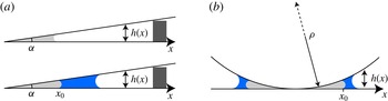
The experimental set-up consists of a slightly tapered and quasihorizontal Hele-Shaw cell, as sketched in figure 1(a). Two glass plates of thickness 3 mm, length 20 cm and width 10 cm face each other and are separated along one edge by a spacer of millimetric thickness. The angle
 ${\it\alpha}$
of the wedge can be tuned between
 $0.1^{\circ }$
and
 $7^{\circ }$
, with an accuracy of
 $0.1^{\circ }$
. The thickness
 $h$
of the gap between the plates is thus of the form
 $h(x)={\it\alpha}x$
, where
 $x$
is the distance to the apex of the wedge. Before forming the wedge, a small amount of a surfactant solution is spread on the glass plates. This thin film of thickness of order
 $1~{\rm\mu}\text{m}$
quickly evaporates, leaving a surfactant layer on the walls. The solution is made with 5 ml of a commercial dishwashing liquid (Paic Citron®, from Colgate–Palmolive Company) diluted in 100 ml of deionized water and methylene blue to enhance the optical contrast. Using a syringe needle, we insert a drop of silicone oil that forms a coin-shaped capillary bridge between the pre-wetted plates. The viscosity
 ${\it\eta}_{o}$
of the oil ranges from 4.5 to 12 200 mPa s. The viscosity
 ${\it\eta}_{w}$
of the aqueous phase is changed from 1 to 600 mPa s by adding fructose to water. The oil migrates towards the apex of the wedge since it wets the surface of the glass. Once the oil is trapped in the wedge, we introduce a large amount of surfactant solution between the plates. The solution also migrates towards the apex of the wedge, and forms with the oil phase an interface initially parallel to the edge. The interfacial tension of the oil/surfactant solution
 ${\it\gamma}$
, measured using the pendant drop and spinning drop methods, ranges from
 $2.3\pm 0.2$
to
 $3.2\pm 0.2~\text{mN}~\text{m}^{-1}$
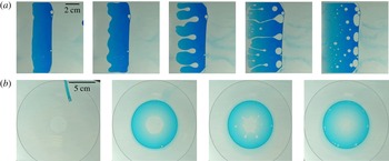
depending on the oil. A white LED backlighting panel is placed under the plates and the system is imaged from above using a digital camera. We observe (figure 2(a) and supplementary movie available at http://dx.doi.org/10.1017/jfm.2016.1) that the oil/water interface destabilizes within a few minutes. The interface becomes wavy, which progressively leads to the formation of oil droplets. These droplets are in a non-wetting situation and are eventually ejected towards less confined regions. As depicted in figure 2(a), the oil and water phases have switched positions after a few minutes. The oil phase is thus extracted and may be recovered out of the device using, for instance, a transverse flow.
Geometry of the experimental set-up: (a) linear wedge, (b) parabolic gap.

We also perform experiments in cells with an axisymmetric geometry to avoid boundary effects. We use the gap between a spherical glass lens and a flat glass plate, as described in figure 1(b). The radius of curvature
 ${\it\rho}$
of the curved surface ranges from 7 to 29 cm. The gap profiles are then parabolic,
 $h(x)=x^{2}/2{\it\rho}$
, where
 $x$
is the distance to the contact point between the curved and flat surfaces. As in the case of the experiments conducted in a wedge geometry, we first pre-wet the cell with the surfactant solution. We then introduce a given volume of silicone oil, which settles around the centre of the cell, where the thickness is minimal. We finally introduce the surfactant solution. Again, oil is extracted in the form of flat circular droplets that migrate away from the centre, driven by the gradient of confinement (see figure 2
b).
As a first step towards understanding the role of physical chemistry in this problem, we have carried out additional experiments with other trapped/extracting liquid pairs. The influence of the surfactant was tested by extracting silicone oil with sodium dodecyl sulphate (SDS) solutions. To avoid using surfactant, we also carried out experiments with pure liquids, and extracted a fluorinated oil (perfluorodecalin) with ethanol.
(a) Top view of a set-up with a straight wedge between two glass plates (see also supplementary movie). The apex of the wedge is along the left side of the pictures. The clear liquid initially located along the edge of the wedge is silicone oil of viscosity
 ${\it\eta}_{o}=50.2$
mPa s. The soap solution is dyed with methylene blue. The oil/water interface destabilizes and oil fingers grow into the water phase. The fingers pinch off and form oil droplets that move away, driven by the gradient in confinement. The inversion of the oil and water phases takes approximately 10 min. (b) Top view of a set-up with a parabolic gap between a glass plate and a spherical lens. Initially (b), the oil phase is trapped close to the plane/sphere contact point. When introduced, the surfactant solution forms an annulus around the oil at the centre of the cell. As in the case of a straight wedge, the oil phase is extracted and driven away from the centre by the gradient of confinement.

3 Size of the extracted oil droplets
3.1 Experimental results
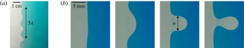
Upon introduction of the extracting solution, the oil/water interface becomes wavy and oil fingers develop in the water-filled region, as shown in figure 2. These fingers progressively pinch off in the form of flattened oil droplets lubricated by a thin water layer. The droplets subsequently migrate away from the tip of the wedge driven by the gradient of confinement. As oil drops are extracted, the boundary between the displacing water and the remaining trapped oil recedes towards the confined region. We observe that the fingers forming closer to the apex of the wedge are smaller than those developing in less confined regions. In early stages of the instability, the oil/water interface sometimes exhibits sinusoidal spatial oscillations, from which we define the dominant wavelength
 ${\it\lambda}$
of the instability, as shown in figure 3(a). In most experiments however, the deformations of the interface are less regular (as it is the case with any instability when the wave mode is not imposed). Then, as a characteristic size, we choose to measure the width
 $w$
of fingers just before the necking process that leads to the pinch off and the release of the drops (figure 3
b).
(a) Depending on initial defects, the oil/water interface sometimes exhibits a regular sinusoidal deformation. In this case, we define the wavelength
 ${\it\lambda}$
of the instability. (b) In most experiments, the pattern is not periodic. Here, we show successive snapshots of an isolated oil finger growing into the water phase and starting to pinch off. For such irregular patterns, a second characteristic size can be defined as the width
 $w$
of the finger at the beginning of the necking and detachment process.

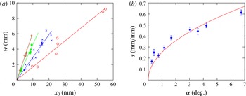
In figure 4(a), we plot the width of the finger
 $w$
as a function of the position
 $x_{0}$
where oil drops are formed in the case of a straight wedge. The width
 $w$
is known to an accuracy of
 $300~{\rm\mu}\text{m}$
, and the uncertainty in
 $x_{0}$
ranges from 2 % to 10 % depending on
 ${\it\alpha}$
. For a given angle
 ${\it\alpha}$
of the wedge,
 $w$
increases linearly with
 $x_{0}$
, which confirms our first qualitative observations. The slope
 $s=\text{d}w/\text{d}x_{0}$
of the line
 $w(x_{0})$
is found to increase with
 ${\it\alpha}$
. As shown in figure 4(b), the variation of
 $s$
with
 ${\it\alpha}$
is well described by a square root law:
 $s\simeq 0.25{\it\alpha}^{1/2}$
(where
 ${\it\alpha}$
is expressed in degrees) within the range of explored angles.
(a) The width
 $w$
of the growing oil fingers as a function of the position of their formation
 $x_{0}$
. The symbols correspond to different values of the wedge angle
 ${\it\alpha}$
:
 $0.25^{\circ }$
(○),
 $1.15^{\circ }$
(
 $\times$
),
 $3.0^{\circ }$
(●) and
 $6.8^{\circ }$
(
 $+$
). The solid lines are linear fits of the data for each value of
 ${\it\alpha}$
. (b) The slope
 $s$
of the line
 $w(x_{0})$
as a function of the wedge angle
 ${\it\alpha}$
. The equation of the full line is
 $s=0.25{\it\alpha}^{1/2}$
, where
 ${\it\alpha}$
is expressed in degrees. The error bars represent the uncertainty in
 $s$
while fitting.

3.2 Mode selection
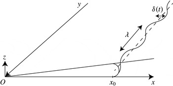
We first aim at giving a physical explanation of the observed results. The oil/water interface is initially flat and located at position
 $x_{0}$
. We consider a perturbation of the interface profile of wavelength
 ${\it\lambda}$
and peak-to-peak amplitude
 ${\it\delta}(t)$
. We describe the tip of the corrugated interface profile by
 $f(x_{0},y)$
, as sketched in figure 5:
 $$\begin{eqnarray}f(x_{0},y)=x_{0}+\frac{{\it\delta}(t)}{2}\cos \left(\frac{2{\rm\pi}y}{{\it\lambda}}\right).\end{eqnarray}$$
Oil/water interfacial harmonic perturbation of wavelength
 ${\it\lambda}$
and amplitude
 ${\it\delta}(t)$
evolving with time. The oil/water interface is located at an average distance
 $x_{0}$
from the apex of the wedge.

Deformations give rise to inhomogeneities in the Laplace pressure jump across the interface, which are responsible for the flow of the oil and water phases. In our experiments, the oil is generally much more viscous than the water (
 ${\it\eta}_{o}/{\it\eta}_{w}\gtrsim 5$
). As a consequence, the pressure in the water is almost constant, and most of the variations occur in the oil phase. Denoting by
 $p_{w}$
the pressure in the water, the pressure
 $p_{o}$
in the oil is given by the Laplace law, expressed as follows in a Hele-Shaw geometry:
 $$\begin{eqnarray}p_{o}=p_{w}+{\it\gamma}\left(\frac{2}{h(x)}-\frac{{\rm\pi}}{4}f^{\prime \prime }(y)\right).\end{eqnarray}$$
The two contributions to the pressure jump correspond to the interface being curved in the
 $Oxz$
and
 $Oxy$
planes respectively. The
 ${\rm\pi}/4$
prefactor accounts for a subtle coupling between the two curvatures and has been described in detail by Park & Homsy (Reference Park and Homsy1984).
Along the interface, in the
 $Oxy$
plane, the characteristic curvature of the interface
 ${\mathcal{C}}_{1}\sim f^{\prime \prime }(y)$
undergoes variations of order
 ${\rm\Delta}{\mathcal{C}}_{1}\sim {\it\delta}/{\it\lambda}^{2}$
. This curvature results in a pressure jump at the oil/water interface, which tends to drive fluid back to the flat interface configuration. Destabilization arises from the interfacial curvature in the
 $Oxz$
plane normal to the plates and the wedge apex, which is of order
 ${\mathcal{C}}_{2}\sim 1/h(x_{0})$
. The curvature difference between crests and troughs is thus of order
 ${\rm\Delta}{\mathcal{C}}_{2}\sim {\it\delta}h^{\prime }(x_{0})/h(x_{0})^{2}$
. Combining both contributions, the global pressure difference between a trough and a crest is approximately
 $$\begin{eqnarray}{\rm\Delta}P\sim {\it\gamma}{\it\delta}\left(\frac{h^{\prime }(x_{0})}{h(x_{0})^{2}}-\frac{1}{{\it\lambda}^{2}}\right).\end{eqnarray}$$
As a consequence, the interface is unstable to all corrugations, such that
 ${\rm\Delta}P>0$
. Perturbations of wavelength larger than
 ${\it\lambda}_{c}\sim h(x_{0})/\sqrt{h^{\prime }(x_{0})}$
are thus amplified.
A pressure gradient of order
 ${\rm\Delta}P/{\it\lambda}$
drives a flow at velocity
 $v\sim \dot{{\it\delta}}$
in a region of typical size
 ${\it\lambda}$
around the mean position
 $x_{0}$
of the interface. Considering that the velocity gradients are mostly normal to the walls, the Stokes equation describing the flow can thus be written dimensionally in the following way:
 $$\begin{eqnarray}{\it\eta}\frac{\dot{{\it\delta}}}{h(x_{0})^{2}}\sim {\it\gamma}{\it\delta}\left(\frac{h^{\prime }(x_{0})}{{\it\lambda}h(x_{0})^{2}}-\frac{1}{{\it\lambda}^{3}}\right),\end{eqnarray}$$
where
 ${\it\eta}={\it\eta}_{o}+{\it\eta}_{w}$
. Looking for solutions of the form
 ${\it\delta}(t)=A\exp \left({\it\sigma}t\right)$
gives the growth rate
 ${\it\sigma}({\it\lambda})$
of the interfacial instability:
 $$\begin{eqnarray}{\it\sigma}({\it\lambda})\sim \frac{{\it\gamma}}{{\it\eta}}\left(\frac{h^{\prime }(x_{0})}{{\it\lambda}}-\frac{h(x_{0})^{2}}{{\it\lambda}^{3}}\right).\end{eqnarray}$$
Following the more general derivation of Saffman & Taylor (Reference Saffman and Taylor1958) and Al-Housseiny et al. (Reference Al-Housseiny, Tsai and Stone2012), we can deduce a precise expression for the growth rate with prefactors:
 $$\begin{eqnarray}{\it\sigma}({\it\lambda})=\frac{{\it\gamma}}{{\it\eta}}\left(\frac{{\rm\pi}h^{\prime }(x_{0})}{3{\it\lambda}}-\frac{{\rm\pi}^{4}h(x_{0})^{2}}{6{\it\lambda}^{3}}\right).\end{eqnarray}$$
The smallest unstable wavelength
 ${\it\lambda}_{c}$
is thus given by
 $$\begin{eqnarray}{\it\lambda}_{c}=\left(\frac{{\rm\pi}^{3}}{2}\right)^{1/2}\frac{h(x_{0})}{\sqrt{h^{\prime }(x_{0})}},\end{eqnarray}$$
while the fastest unstable mode can be expressed as
 $$\begin{eqnarray}{\it\lambda}^{\ast }=\sqrt{3}{\it\lambda}_{c}.\end{eqnarray}$$
In the configurations we have realized experimentally, the gap profiles
 $h(x)$
are linear or parabolic,
 $h(x)={\it\alpha}x$
or
 $h(x)=x^{2}/2{\it\rho}$
. The expression for
 ${\it\lambda}^{\ast }$
is
 $$\begin{eqnarray}{\it\lambda}^{\ast }=\left(\frac{3{\rm\pi}^{3}}{2}\right)^{1/2}x_{0}\sqrt{{\it\alpha}}\simeq 6.82x_{0}\sqrt{{\it\alpha}}\end{eqnarray}$$
or
 $$\begin{eqnarray}{\it\lambda}^{\ast }=\left(\frac{3{\rm\pi}^{3}}{8}\right)^{1/2}\sqrt{\frac{x_{0}^{3}}{{\it\rho}}}\simeq 3.41\sqrt{\frac{x_{0}^{3}}{{\it\rho}}}\end{eqnarray}$$
respectively.
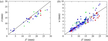
(a) The measured wavelength
 ${\it\lambda}$
of the instability in a linear confinement is plotted as a function of the most unstable wavelength
 ${\it\lambda}^{\ast }$
predicted by (3.9). The symbols correspond different pairs of trapped/extracting liquids: silicone oil/Paic Citron® solution (●), silicone oil/SDS solution (▪) and perfluorodecalin/ethanol (▴). The data are well described by the line of equation
 ${\it\lambda}={\it\lambda}^{\ast }$
. (b) The width
 $w$
of oil fingers plotted as a function of the most unstable wavelength
 ${\it\lambda}^{\ast }$
as predicted by (3.9) and (3.10) in both linear and parabolic confinements. The open circles (○) correspond to experiments in a parabolic gap. The experimental data for both geometries are consistent with a linear law
 $w\simeq 0.28{\it\lambda}^{\ast }$
(full line).

In figure 6(a), we plot the experimentally measured wavelength
 ${\it\lambda}$
of the instability as a function of
 ${\it\lambda}^{\ast }$
, for straight wedges of various angles
 ${\it\alpha}$
, different values of
 $x_{0}$
and silicone oils of viscosity
 ${\it\eta}_{o}$
ranging from 4.5 to 970 mPa s. We observe that the data are in good agreement with the prediction of (3.9) without any adjustable parameter. Additional data corresponding to silicone oil/SDS solution and perfluorodecalin/ethanol also follow the same trend, showing that the observed size selection process does not depend significantly on the type or even on the presence of surfactant. In most cases, however, it was not possible to observe an interface oscillating with a single wavelength, which is why the data points in figure 6(a) are relatively scarce. Using the width
 $w$
of a pinching finger as a characteristic size, we could collect more data, which are displayed in figure 6(b); these data also include experiments in parabolic wedges with various radii of curvature
 ${\it\rho}$
. Again, we observe that all of the data superimpose on a line of equation
 $w\simeq 0.28{\it\lambda}^{\ast }$
, indicating that the first stages of the instability determine how
 $w$
scales with the experimental parameters. The numerical coefficient is probably determined by the details of the instability in the later nonlinear stage (
 ${\it\delta}\gtrsim {\it\lambda}$
). The data nevertheless exhibit some scattering, which may be due to hydrodynamic interactions between neighbouring fingers in nonlinear stages of the instability. For instance, we sometimes observe that a finger starts to grow but is finally absorbed by one of its closest neighbours, which results in a larger drop.
4 Dynamics of the instability
4.1 Experimental results
Numerous studies in the literature on viscous fingering compare the experimentally observed shapes of fingers with theoretical and numerical predictions, relying on refined versions of initial models by Saffman & Taylor (Reference Saffman and Taylor1958). However, very few authors report direct measurements of the growth rates of the instability. The work of Park, Gorell & Homsy (Reference Park, Gorell and Homsy1984a ) (see also the corrigendum of Park, Gorell & Homsy (Reference Park, Gorell and Homsy1984b )) provides growth rates for a restricted range of fluid viscosities, showing discrepancies with a model adapted from Saffman & Taylor (Reference Saffman and Taylor1958).
Here, we propose to characterize the dynamics of the instability with two time scales. A first time corresponds to the growing time of a finger developing at a given distance
 $x_{0}$
from the apex of the wedge (we focus on the case of a straight wedge,
 $h(x)={\it\alpha}x$
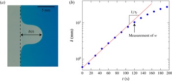
). As shown in figure 7, the amplitude of the instability
 ${\it\delta}(t)$
grows exponentially as long as the shape of the finger is not fully developed. Within the limit
 ${\it\delta}\lesssim {\it\lambda}$
, the amplitude of the finger is thus given by
 ${\it\delta}(t)=A\exp (t/{\it\tau}_{f})$
, where the characteristic growth time
 ${\it\tau}_{f}$
depends on the fluid viscosities, interfacial tension and initial position
 $x_{0}$
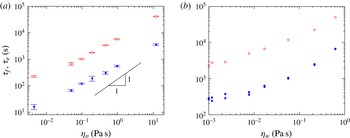
. In figure 8(a) (filled blue symbols), we plot
 ${\it\tau}_{f}$
as a function of the oil viscosity
 ${\it\eta}_{o}$
for a wedge of angle
 ${\it\alpha}=0.95^{\circ }$
and an interface at an initial position
 $x_{0}=20.5\pm 2.5~\text{mm}$
. As
 ${\it\eta}_{o}$
varies from 4.5 to 12 200 mPa s,
 ${\it\tau}_{f}$
increases from 10 s to approximately 1 h. Experimentally,
 ${\it\tau}_{f}$
is found to increase as a power law,
 ${\it\tau}_{f}\propto {\it\eta}_{o}^{0.7}$
.
The amplitude
 ${\it\delta}(t)$
represents the length of a growing finger evolving in time. The amplitude
 ${\it\delta}$
increases exponentially with time in the first stages of the development of the finger, which provides a characteristic growing time
 ${\it\tau}_{f}$
as the inverse growth rate of
 ${\it\delta}$
. The arrow indicates the time at which the finger width
 $w$
is measured.

Another relevant time scale is the extraction time of the whole volume of oil trapped inside the wedge. This global time
 ${\it\tau}_{e}$
corresponds to the time after water injection at which all of the trapped oil is set into motion in the form of droplets. Figure 8(a) (open red symbols) also shows the variation of
 ${\it\tau}_{e}$
versus
 ${\it\eta}_{o}$
, the other parameters being the same as for the measurement of
 ${\it\tau}_{f}$
. Again, we observe that
 ${\it\tau}_{e}$
increases with a power law,
 ${\it\tau}_{e}\propto {\it\eta}^{0.75}$
. While the exponent is almost the same as for the first measurement, the prefactor is larger by a factor of order 10.
(a) Characteristic oil extraction time scales plotted as a function of the oil viscosity
 ${\it\eta}_{o}$
. Here,
 ${\it\tau}_{f}$
(●) is the inverse growth rate of the dominant wavelength for an interface initially at a distance
 $x_{0}=20.5\pm 2.5$
mm from the apex of a wedge of angle
 ${\it\alpha}=0.95^{\circ }$
;
 ${\it\tau}_{e}$
(○) corresponds to the time at which all of the trapped oil is set into motion. Both sets of data follow the same scaling trend (
 ${\it\tau}_{f}\sim {\it\eta}^{0.71}$
,
 ${\it\tau}_{e}\sim {\it\eta}^{0.75}$
), although with different prefactors. The error bars represent the standard deviation of the distribution of
 ${\it\tau}$
for a given
 ${\it\eta}_{o}$
. (b) Characteristic oil extraction time scales plotted as a function of the extracting liquid viscosity
 ${\it\eta}_{w}$
. Here,
 ${\it\tau}_{f}$
(●) is the inverse growth rate of the dominant wavelength for an interface initially at a distance
 $x_{0}=20.5\pm 2.5$
mm from the apex of a wedge of angle
 ${\it\alpha}=0.95^{\circ }$
;
 ${\it\tau}_{e}$
(○) corresponds to the time at which all of the trapped oil is set into motion. As
 ${\it\eta}_{w}$
increases by three orders of magnitude, the extraction times gain a factor of approximately 30.

We also explore the role of the viscosity
 ${\it\eta}_{w}$
of the extracting phase by using fructose solutions of various concentrations as the extracting phase (
 ${\it\eta}_{w}$
ranges from 1 to approximately 600 mPa s). In figure 8(b), we show the evolution of
 ${\it\tau}_{f}$
and
 ${\it\tau}_{e}$
as a function of
 ${\it\eta}_{w}$
. The oil viscosity is fixed in these experiments,
 ${\it\eta}_{o}=500$
mPa s. As expected, the fingers grow faster for smaller values of
 ${\it\eta}_{w}$
. As
 ${\it\eta}_{w}$
increases by three orders of magnitude, the extraction times indeed gain a factor of approximately 30. However, the relationship is apparently not a simple scaling law here.
4.2 Discussion
Inputting the wavelength
 ${\it\lambda}^{\ast }$
into (3.6) gives the corresponding growth rate:
 $$\begin{eqnarray}{\it\sigma}^{\ast }={\it\sigma}({\it\lambda}^{\ast })=\left(\frac{8}{243{\rm\pi}}\right)^{1/2}\frac{{\it\gamma}}{{\it\eta}}\frac{h^{\prime }(x_{0})^{3/2}}{h(x_{0})}.\end{eqnarray}$$
For a straight wedge,
 $h(x)={\it\alpha}x$
, the time scale
 ${\it\tau}^{\ast }=1/{\it\sigma}^{\ast }$
is thus given by
 $$\begin{eqnarray}{\it\tau}^{\ast }=\left(\frac{243{\rm\pi}}{8}\right)^{1/2}\frac{{\it\eta}}{{\it\gamma}}\frac{x_{0}}{\sqrt{{\it\alpha}}}.\end{eqnarray}$$
As a consequence, one would thus expect the characteristic time scales of the instability to be proportional to
 ${\it\eta}={\it\eta}_{o}+{\it\eta}_{w}$
. The data displayed in figure 8(a), for which
 ${\it\eta}\simeq {\it\eta}_{o}$
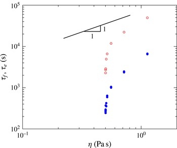
, do not agree well with this prediction. Figure 9 shows the same data as figure 8(b) plotted as a function of
 ${\it\eta}$
instead of
 ${\it\eta}_{w}$
. The discrepancy with the theoretical prediction is even more striking, and the experimental data clearly disagree with the conclusion that
 ${\it\tau}_{f}$
,
 ${\it\tau}_{e}\propto {\it\eta}$
.
The time scales
 ${\it\tau}_{f}$
and
 ${\it\tau}_{e}$
as a function of
 ${\it\eta}={\it\eta}_{o}+{\it\eta}_{w}$
for a subset of data with a fixed oil viscosity
 ${\it\eta}_{o}=500~\text{mPa}~\text{s}$
. The characteristic time scales are clearly not proportional to
 ${\it\eta}$
, showing that the classical model for viscous fingering cannot describe the dynamics of growing fingers in the current situation.

We now discuss some possible reasons for this discrepancy. We suspect that dynamic wetting phenomena may play an important role here. As the water phase wets the cell preferentially, a thin film of water is deposited between the oil and the glass walls as the fingers grow. Hodges, Jensen & Rallison (Reference Hodges, Jensen and Rallison2004) studied theoretically the effects of dynamic wetting on the motion of a drop translating in a cylindrical tube filled with another immiscible viscous liquid. The end caps and main body of the drop couple to the lubricating film of the outer fluid, giving rise to a number of asymptotic regimes that strongly depend on the viscosity ratio of the two liquids, the drop size and the capillary numbers. The analysis of Hodges et al. (Reference Hodges, Jensen and Rallison2004) in the case of rotational symmetry remains valid, but other effects should add up in a Hele-Shaw geometry. Recently, Huerre et al. (Reference Huerre, Theodoly, Leshansky, Valignat, Cantat and Jullien2015) have shown that the dynamics of drops in microfluidic devices is strongly influenced by the lubrication films that separate the drop from the walls. The variety of possible dissipation mechanisms makes it difficult to derive an analytical expression for the temporal evolution of the amplitude of fingering instabilities. It is still a topic of debate, and recent works discussing the complexity of patterns obtained in the radial Saffman–Taylor instability show that the resulting dynamics is far from being fully understood (Bischofberger, Ramachandran & Nagel Reference Bischofberger, Ramachandran and Nagel2014; Jackson et al. Reference Jackson, Stevens, Giddings and Power2015). Here, we discuss some possible physical mechanisms involved at the interface between the two fluids.
Viscous friction associated with moving contact lines has been widely documented in the past. In particular, the work of Landau & Levich (Reference Landau and Levich1942) and Bretherton (Reference Bretherton1961), recently revisited by Cantat (Reference Cantat2013), enables one to predict the viscous force associated with a contact line moving and depositing a thin film of the displaced liquid (usually water in the present experiment). The force per unit length of the moving meniscus scales as
 ${\it\gamma}Ca_{w}^{2/3}$
, where
 $Ca_{w}={\it\eta}_{w}V/{\it\gamma}$
and
 $V$
is the interface velocity. This prediction is, in particular, important in the dynamics of foams sliding against a wall (Cantat Reference Cantat2013). It also enables one to account for the motion of a drop bridging the walls of a Hele-Shaw cell and flowing under its own weight (Reyssat Reference Reyssat2014). Equivalently, Park & Homsy (Reference Park and Homsy1984) have shown that in the case of a non-wetting fluid displacing a wetting phase in a Hele-Shaw cell, dynamic wetting modifies the interfacial pressure jump by adding a term of order
 $({\it\gamma}/h)Ca_{w}^{2/3}$
. Following the steps of Park & Homsy (Reference Park and Homsy1984), a number of authors (Schwartz Reference Schwartz1986; Reinelt Reference Reinelt1987; Maxworthy Reference Maxworthy1989; Jackson et al.
Reference Jackson, Stevens, Giddings and Power2015) have included contact line dissipation in this manner, and have concluded that accounting for dynamic wetting gives better predictions of the fingering patterns in the Saffman and Taylor instability. Implementing this additional term into (3.3) leads to a modified expression for the driving pressure difference:
 $$\begin{eqnarray}{\rm\Delta}P\sim {\it\gamma}{\it\delta}\left(\frac{h^{\prime }(x_{0})}{h(x_{0})^{2}}-\frac{1}{{\it\lambda}^{2}}\right)-{\it\varepsilon}\frac{{\it\gamma}}{h(x_{0})}\left(\frac{{\it\eta}_{w}\dot{{\it\delta}}}{{\it\gamma}}\right)^{2/3},\end{eqnarray}$$
where
 ${\it\varepsilon}$
is a constant of order 1. Taking into account the viscosities of both fluids may modify this term. Nevertheless, Schwartz, Princen & Kiss (Reference Schwartz, Princen and Kiss1986) demonstrated that the viscosity ratio between the two fluids only slightly alters
 ${\it\varepsilon}$
by a factor of at most 1.6. The evolution equation for the amplitude of the instability thus becomes
 $$\begin{eqnarray}{\it\gamma}{\it\delta}\left(\frac{h^{\prime }(x_{0})}{h(x_{0})^{2}}-\frac{1}{{\it\lambda}^{2}}\right){\it\lambda}h(x_{0})\sim {\it\eta}\frac{\dot{{\it\delta}}}{h(x_{0})^{2}}{\it\lambda}^{2}h(x_{0})+{\it\varepsilon}{\it\gamma}{\it\lambda}\left(\frac{{\it\eta}_{w}\dot{{\it\delta}}}{{\it\gamma}}\right)^{2/3}.\end{eqnarray}$$
In (4.4), the velocity appears both in the product
 ${\it\eta}\dot{{\it\delta}}$
of the usual Poiseuille term and as
 ${\it\eta}_{w}\dot{{\it\delta}}$
in the nonlinear contact line friction. One thus cannot expect characteristic growth times to simply scale linearly with
 ${\it\eta}={\it\eta}_{o}+{\it\eta}_{w}$
in general. Interfacial dissipation should initially dominate until the velocity reaches a critical value defined by
 $$\begin{eqnarray}\dot{{\it\delta}}^{\ast }\sim \frac{{\it\gamma}}{{\it\eta}}\left(\frac{{\it\eta}_{w}}{{\it\eta}}\right)^{2}\left(\frac{h}{{\it\lambda}}\right)^{3}.\end{eqnarray}$$
In our experiments,
 ${\it\eta}_{w}/{\it\eta}$
ranges from
 $10^{-4}$
to 1,
 $h/{\it\lambda}\sim \sqrt{{\it\alpha}}\sim 10^{-1}$
, so that
 $\dot{{\it\delta}}^{\ast }\lesssim 10^{-4}{\it\gamma}/{\it\eta}$
. In most experiments, the measured velocities are such that the criterion given by (4.5) is satisfied before
 ${\it\delta}$
reaches the local thickness
 $h(x_{0})$
of the cell. Meniscus friction is thus in most cases negligible.
Once deposited by the moving meniscus, the water film also modifies the boundary condition seen by the oil finger at the walls of the Hele-Shaw cell: the flow is no longer localized in the oil phase, but some degree of slippage is now allowed and the water film is also under shear. Considering an oil finger of thickness
 $h$
separated from the walls by water films of thickness
 $e$
, localization of the flow within the most mobile phase depends on the ratio
 $r=h{\it\eta}_{w}/e{\it\eta}_{o}$
. Given that
 $e\sim hCa_{w}^{2/3}$
,
 $r$
is found to range from 0.1 to 100 in our experiments, indicating that water films may efficiently lubricate oil fingers. Such lubricating films have been shown to play a dominant role in the motion of oil slugs self-propelling in capillary tubes (Bico & Quéré Reference Bico and Quéré2002). As the oil becomes very viscous, it essentially flows as a solid plug lubricated by a film of low viscosity. While such an effect may be important, we expect it to be weaker in our two-dimensional system where flows have an extensional component. Even for perfectly lubricated flows (
 $r\ll 1$
), velocity gradients in the plane of the plates remain and should then contribute. Associated viscous forces (per unit volume) are of order
 ${\it\eta}_{o}\dot{{\it\delta}}/{\it\lambda}^{2}$
. This additional dissipative term involves only the oil viscosity, showing one more time that one should probably not expect a simple linear link between the characteristic times of the instability and
 ${\it\eta}={\it\eta}_{o}+{\it\eta}_{w}$
. Lubrication by water films qualitatively explains the trends presented in figures 8 and 9. For a fixed viscosity of the water phase (figure 8
a),
 ${\it\tau}$
increases sublinearly with
 ${\it\eta}$
, in agreement with the stronger effect of lubrication as the viscosity ratio
 ${\it\eta}_{o}/{\it\eta}_{w}$
increases. In the case of fixed
 ${\it\eta}_{o}$
(figure 9), as
 ${\it\eta}_{w}$
increases,
 ${\it\tau}$
grows more quickly than
 ${\it\eta}$
as lubrication becomes less efficient.
Additional complexity also emerges from the physicochemical properties of the interface. As shown by Cantat (Reference Cantat2013), both the numerical coefficient and the exponent in contact line dissipation depend on the interfacial rheology, i.e. on the type of surfactant used. More generally, the motion of the drop and bubbles is known to be affected by the presence of surface-active molecules (Levich Reference Levich1962). Since surfactant molecules from the interface are advected by the flow around the drop, the interface freshly created at the front of the drop is depleted in surfactant in comparison to the rear of the drop where surface-active molecules accumulate. As a consequence, surface stresses develop and generate Marangoni flows which affect the primary flow. Such surface tension gradients oppose and reduce the rising velocity of gas bubbles ascending in a surfactant solution, as shown by Ybert & di Meglio (Reference Ybert and di Meglio2000). Air bubbles rising in inclined Hele-Shaw cells flooded with surfactant solutions also develop an anomalous wake and tend to rise more slowly than in pure water (Bush Reference Bush1997). A similar effect may thus operate in our case. The crests and troughs of the interface probably have different surfactant interfacial concentrations, giving rise to Marangoni stresses which may modify the growth of oil fingers. Nevertheless, experiments conducted with different surfactants, or even without surfactant, show that the size of the produced droplets is not significantly altered, which suggests that this effect should not be dominant in our experiments.
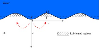
Finally, it may seem surprising that the minimal model recalled above, although unable to faithfully describe the dynamics of the instability, predicts the dominant wavelength accurately. As the instability develops, oil fingers invade the initially water-filled region and become gradually lubricated by the water films deposited by the moving interface. As shown in figure 10, in the early stages, within one finger, the surface of the non-lubricated moving oil is of order
 ${{\it\lambda}^{\ast }}^{2}$
, while the lubricated fraction of the finger covers an area
 ${\it\lambda}^{\ast }{\it\delta}$
. The dominant wavelength may be selected in these first moments where the resisting forces originate mostly from the classical Poiseuille flow in both phases;
 ${\it\lambda}^{\ast }$
then remains locked as the instability develops further. Lubrication by water films should mainly only affect these later stages, where it may accelerate the growth of fingers whose size is already selected.
Qualitative sketch illustrating the regions where oil is lubricated by water films. The main directions of the oil flow in the plane of the plates are indicated by the dashed arrows, showing that in-plane velocity gradients may contribute to viscous dissipation in the bulk of the oil phase when lubrication is efficient.

5 Conclusion
We have explored experimentally the exchange mechanism of two competing fluids in wedges. The extraction of the first introduced phase (mainly silicone oil in the present study) by a more wetting liquid results from a capillary-driven instability due to antagonist principal curvatures of the oil/water interface, which is reminiscent of the classical Rayleigh–Plateau instability (de Gennes, Brochard-Wyart & Quéré Reference de Gennes, Brochard-Wyart and Quéré2004). This instability produces oil fingers that pinch off into flat droplets which are eventually displaced to the regions of low confinement. The size of the droplets depends on the value of the local thickness and its gradient. In addition, we have also measured the dynamics of the instability for wide viscosity ranges of both phases, and have shown discrepancies with the simplest model. We have discussed possible dissipation mechanisms, and believe that they may be more complex than those discussed in the literature on viscous fingering. We suspect dynamic wetting effects to play an important role in the characteristic time scale of the instability, and we hope that our experimental study will motivate further theoretical or numerical exploration of the problem.
Physical chemistry issues are also certainly crucial and a source of many open questions. It could be interesting to probe interfacial effects by changing the type of surfactant employed, the hydrophilic–lipophilic balance or the mobility. Oil extraction may even occur in some systems in the absence of surface-active molecules. More generally, exploration of the behaviour of complex fluids such as polymer solutions, suspensions, foams or emulsions may be relevant to the petroleum industry. The configuration we investigated only involves a total wetting of the water phase. Is oil extraction still spontaneous if water only partially wets the walls, as frequently occurs in oil fields? If contact angle hysteresis impedes the motion, could the instability be triggered by mechanically actuating the walls of the cell as the ‘capillary ratchet’ described by Prakash, Quéré & Bush (Reference Prakash, Quéré and Bush2008)? The plates used in our experiments were smooth; it would thus be interesting to investigate whether the introduction of some roughness would prevent or amplify the liquid exchange.
Acknowledgement
This research has been partially funded by Total S.A. through the Chaire Total/ESPCI and by the Interuniversity Attraction Poles Programme (IAP 7/38 MicroMAST) initiated by the Belgian Science Policy Office.
Supplementary movie
Supplementary movie is available at http://dx.doi.org/10.1017/jfm.2016.1.