
Introduction
Proton exchange membrane fuel cells (PEMFCs) operated in acidic conditions are one of the most promising environment-friendly electrochemical energy conversion devices for next-generation transportation applications due to their ultrahigh theoretical specific energy.[Reference Shao, Chang, Dodelet and Chenitz1] The oxygen reduction reaction (ORR) process at the cathode of PEMFCs involves O2 adsorption, O–O breaking and multi-step electron transfer with high-energy barriers, leading to sluggish kinetics and low efficiency.[Reference He, Tang, Kou, Pan, Sun, Zhang and Mu2] In order to facilitate ORR toward a small overpotential, a high current density, and a long durability, highly efficient, and robust catalysts are needed. Noble-metal Pt-based materials are known as the best ORR catalysts in acidic conditions, but they suffer from conspicuous drawbacks of high cost, scarcity, and poor durability, which severely hinder their wide use in PEMFCs. Thus, extensive research work has been dedicated to exploring inexpensive catalysts with high activity and long-term durability to substitute Pt-based materials.
Carbon-based catalysts, including metal-free heteroatoms (B, N, S, and P)-doped carbon materials[Reference Li, Hou, Zhang, Liu and Cheng3–Reference Tang and Zhang5] and noble-metal-free Fe–N–C materials,[Reference Wang, Zhang, Lin, Gupta, Wang, Tao, Fu, Wang, Zheng, Wu and Li6–Reference Tang, Titirici and Zhang8] are the most promising alternatives due to their desirable electrical conductivity, good chemical stability, and large surface area. Among them, Fe–N–C materials with N-coordinated single-atom Fe (Fe–Nx) active sites have demonstrated the best ORR activity in acidic conditions, and density functional theory calculations suggest that single-atom Fe sites could be as active as Pt for ORR catalysis.[Reference Jiang, Gu, Li, Zhang, Zhang, Zhang, Wang, Hu, Wei and Wan9–Reference Li, Hou, Shi, Zhao, Tang, Cheng, Liu and Cheng11] However, due to the coexistence of abundant nanoparticles (including metallic iron, iron carbide, iron nitride, and iron oxide), traditional Fe–N–C materials show a large potential gap compared with Pt-based catalysts.[Reference Wu, More, Johnston and Zelenay12–Reference Strickland, Miner, Jia, Tylus, Ramaswamy, Liang, Sougrati, Jaouen and Mukerjee14] Recently, extensive research work has been conducted to develop Fe–N–C materials with single-atom Fe-active sites (single-atom Fe catalysts) rather than inactive Fe-containing nanoparticles.[Reference Zhang, Hwang, Wang, Feng, Karakalos, Luo, Qiao, Xie, Wang, Su, Shao and Wu15–Reference Zhu, Fu, Song, Shi, Su, Engelhard, Li, Xiao, Li, Estevez, Du and Lin22] For example, Sa et al. proposed a silica-protective-layer-assisted approach to preferentially form Fe–Nx active sites.[Reference Sa, Seo, Woo, Lim, Cheon, Yang, Lee, Kang, Shin, Shin, Jeong, Kim, Kim, Kim and Joo18] Chen et al. reported single-atom Fe catalysts derived from metal–organic framework.[Reference Chen, Ji, Wang, Dong, Chen, Li, Shen, Zheng, Zhuang, Wang and Li19] Zhang et al. synthesized N-doped porous carbon loaded with single Fe atoms due to confinement effect,[Reference Zhang, Gao, Dou, Ji and Wang20] and our group reported an atomic isolation method to produce single-atom Fe catalysts.[Reference Li, Yang, Tang, Zhang, Hou, Zhao, Liu, Cheng, Li, Zhang and Cheng21] The overpotential gap between Pt catalysts and these single-atom Fe catalysts has been reduced to below 100 mv in an acid condition; however, the ORR performance still cannot satisfy the demand of practical applications. Thus, a rational design and efficient preparation technique is of great importance to obtain single-atom Fe catalysts with excellent ORR performance.
Like traditional Fe–N–C materials, the structure and environment of single-atom Fe catalysts also need to be optimized to achieve desirable mass transport and charge transfer.[Reference Zhu, Fu, Shi, Du and Lin23–Reference Li, Hou and Liu25] Carbon materials with good electrical conductivity, such as carbon black, carbon nanofibers (CNFs), carbon nanotubes (CNTs), and graphene, are usually used as supports to improve electron transfer in noble-metal-free catalysts. However, the definitive correlation between carbon supports and catalytic activity of Fe–Nx active sites still remains to be elusive. Different from traditional Fe–N–C catalysts, single-atom Fe-based catalysts contain atomically dispersed Fe–Nx active sites rather than Fe-containing nanoparticles. This feature makes it possible to detect the concentration of atomic Fe and quantitatively reveal the activity of single-atom Fe-active sites. Consequently, by choosing carbon hosts with different structures and conductivities, the correlation between activity of single-atom Fe-active sites and carbon supports can be disclosed.
Here we use an atomic isolation method[Reference Li, Yang, Tang, Zhang, Hou, Zhao, Liu, Cheng, Li, Zhang and Cheng21] to prepare a series of single-atom Fe catalysts with similar one-dimensional core–shell structures, in which CNFs and CNTs serve as supports (conductive core) to host high-concentration isolated Fe atoms anchored on the outer N-doped porous carbon layer (shell structure). These carbon supports have different degrees of graphitization and therefore different charge transfer capability, while the single-atom Fe-active materials at the shell were kept unchanged. Comparison experiments show that charge transfer is a key step for the ORR. High charge transfer ability of carbon supports not only greatly improves the ORR durability, but also boosts the ORR activity of single-atom Fe-active sites, especially at high overpotentials.
Experimental methods
Material preparation
CNFs were prepared by pyrolyzing bacterial cellulose (kindly provided by C. Y. Zhong, HainanYeguo Foods Co., Ltd., China) at 900°C (denoted as CNF-900) and 1100°C (denoted as CNF-1100) under Ar atmosphere and then impregnated in concentrated nitric acid for 24 h. The functionalized CNF materials were washed with deionized water, dried at 60°C, and ground for use.
CNTs (Nanjing XFNANO Materials Tech Co., Ltd, China) were functionalized by using a modified Hummers method. Briefly, CNTs (0.5 g) and potassium nitrate (0.37 g) were dispersed in 15 mL of concentrated sulfuric acid, followed by gradual addition of potassium permanganate (2.0 g) under vigorous stirring in an ice–water bath. The mixture was then stirred at room temperature for 2 h, followed by gradual addition of water (10 mL) and hydrogen peroxide (30%, 5 mL). After stirring for 2 h, the solution was centrifuged at 10,000 rpm for 2 min. Functionalized CNTs in the sediment were collected using a vacuum filter and washed with deionized water and dried for use.
Seventy-five milligrams of functionalized CNF-900, CNF-1100, or CNTs were dispersed in 37 mL 0.1 M hydrochloric acid solution and mixed with 1.0 mL pyrrole, followed by 10 min sonication and 10 min vigorous stirring. Subsequently, 37 mL solution containing 1.5 g ammonium peroxydisulfate was added drop-wise to the above mixtures under continuous stirring. After stirring for 10 h to allow polymerization, the product was separated by vacuum filtration and washed with ethanol and water. The wet hybrid was then dispersed in 200 mL mixture solution of zinc nitrate (0.4 M) and iron nitrate (10 mM), followed by 2 min sonication and 10 h vigorous stirring to allow it to adsorb Zn2+ and Fe3+ cations. Finally, this hybrid was collected by vacuum filtration and dried at 60°C for 12 h, and then pyrolyzed at 900°C under a 100 standard cubic centimeter per minute (sccm) Ar flow for 30 min and activated under 100 sccm NH3 flow for 30 min. The final catalysts (denoted as CNF-900@Fe–N–C, CNF-1100@Fe–N–C, or CNT@Fe–N–C) were collected and cooled to room temperature under an NH3 flow.
Electrochemical measurements
Electrochemical measurements were performed using an electrochemical analysis station (CHI 760 E, CH Instruments, China) with a standard three-electrode cell. A graphite rod and an Ag/AgCl electrode in a saturated KCl solution served as the counter electrode and reference electrode, respectively. All potential values refer to that of a reversible hydrogen electrode. A rotating ring-disk electrode (RRED) with a glass carbon disk (5.61 mm diameter) and a Pt ring (6.25 mm inner diameter and 7.92 mm outer diameter) were used as the substrate of a working electrode to evaluate the ORR performance. To prepare the working electrode, 4.0 mg of each catalyst was ultrasonically dispersed in ethanol containing 0.05 wt.% Nafion (2.0 mL) to form a concentration of 2.0 mg/mL catalyst ink. The catalyst ink was then coated on the surface of the glassy carbon disk for the RRDE tests. The non-noble-metal catalyst loading was 0.24 mg/cm2. Pt/C (20 wt.%, Alfa Aesar) with a “standard” loading of 0.1 mg/cm2 was used as a reference sample. The stability test was performed at 0.7 V in 0.1 M HClO4 for chronoamperometry at room temperature with a working electrode rotation rate of 1600 rpm.
Turn-over frequency (TOF, number of electrons reduced per Fe–N–C active site and per second at 0.8 V) was calculated according to the following formula:
 $$\eqalign{\hbox{TOF} &= \displaystyle{{\,j_{\rm k}} \over {\displaystyle{{W_{{\rm Fe}}} \over {M_{{\rm Fe}}}} \times N_{\rm A} \times m_{{\rm loading}}}} \cr &= \displaystyle{{\vert {\,j_{\rm k}} \vert \lpar {\hbox{mA} \cdot \hbox{cm}^{ - 2}} \rpar \times {10}^{ - 3}\lpar {\hbox{A} \cdot \hbox{mA}^{ - 1}} \rpar } \over {\displaystyle{{{10}^{ - 2} \times \vert {W_{{\rm Fe}}} \vert \lpar {\hbox{wt}.\%} \rpar } \over {\hbox{55.85}\lpar {\hbox{g} \cdot \hbox{mol}^{ - 1}} \rpar }} \times \hbox{6.02} \times \hbox{10}^{{\rm 23}}\lpar {\hbox{site} \cdot \hbox{mol}^{ - 1}} \rpar \times \hbox{0.24} \times \hbox{10}^{ - {\rm 3}}\lpar {\hbox{g} \cdot \hbox{cm}^{ - 2}} \rpar }} \cr &= \displaystyle{{\vert {\,j_{\rm k}} \vert \lpar {\hbox{mA} \cdot \hbox{cm}^{ - 2}} \rpar \times {10}^{ - 3}\lpar {\hbox{C} \times \hbox{s}^{ - 1} \cdot \hbox{mA}^{ - 1}} \rpar } \over {\displaystyle{{{10}^{ - 2} \times \vert {W_{{\rm Fe}}} \vert \lpar {\hbox{wt}.\%} \rpar } \over {\hbox{55.85}\lpar {\hbox{g} \cdot \hbox{mol}^{ - 1}} \rpar }} \times \hbox{6.02} \times \hbox{10}^{{\rm 23}}\lpar {\hbox{site} \cdot \hbox{mol}^{ - 1}} \rpar \times \hbox{0.24} \times \hbox{10}^{ - {\rm 3}}\lpar {\hbox{g} \cdot \hbox{cm}^{ - 2}} \rpar }} \cr &= \displaystyle{{\vert {\,j_{\rm k}} \vert \lpar {\hbox{mA} \cdot \hbox{cm}^{ - 2}} \rpar \times {10}^{ - 3} \times 6.25 \times {10}^{18}\lpar {\hbox{e}^ - \cdot \hbox{s}^{ - 1} \cdot \hbox{mA}^{ - 1}} \rpar } \over {\displaystyle{{{10}^{ - 2} \times \vert {W_{{\rm Fe}}} \vert \lpar {\hbox{wt} \%} \rpar } \over {\hbox{55.85}\lpar {\hbox{g} \cdot \hbox{mol}^{ - 1}} \rpar }} \times \hbox{6.02} \times \hbox{10}^{{\rm 23}}\lpar {\hbox{site} \cdot \hbox{mol}^{ - 1}} \rpar \times \hbox{0.24} \times \hbox{10}^{ - {\rm 3}}\lpar {\hbox{g} \cdot \hbox{cm}^{ - 2}} \rpar }} \cr &= \hbox{0.246} \times \displaystyle{{\vert {\,j_{\rm k}} \vert } \over {\vert {W_{{\rm Fe}}} \vert }} \lpar {\hbox{e}^ - \cdot \hbox{sit}\hbox{e}^{ - 1} \cdot \hbox{s}^{ - 1}} \rpar } $$
Where W Fe and M Fe (|M Fe| = 55.85 g/mol) are the mass fraction and molar mass of Fe, respectively. W Fe is measured from inductively coupled plasma mass spectrometry (ICP-MS) analysis. j k is the mass transfer corrected kinetic current density at 0.8 V. N A is Avogadro's number (6.02 × 10²³/mol).
Results and discussion
We selected one-dimensional CNTs and CNFs with a similar structure and different degrees of graphitization as supports. The CNTs were purchased from XFNANO corporation. The CNFs were prepared by the carbonization of bacterial cellulose at 900°C (denoted as CNF-900) and 1100°C (denoted as CNF-1100), and the detailed synthesis process are described in supporting information (SI). A higher carbonization temperature generally leads to better graphitization and electrical conductivity of carbon materials. CNF-1100 is expected to possess higher electrical conductivity than CNF-900. The single-atom Fe sites anchored on the outer N-doped porous carbon layer were loaded on CNT/CNF supports by using a modified atomic isolation method,[Reference Li, Yang, Tang, Zhang, Hou, Zhao, Liu, Cheng, Li, Zhang and Cheng21] which involves pyrrole polymerization on carbon supports, Fe3+/Zn2+ adsorption, and high-temperature pyrolysis (for details see Material preparation of SI). Raman spectroscopy was used to evaluate the graphitization degrees of these one-dimensional carbons and the results are shown in Figure S1. Compared with CNFs, the CNTs show obviously narrower G-band and D-band peaks (smaller full width at half maximum, FWHM), suggesting that the CNTs possess better graphitization degree.[Reference Li, Zhao, Hou, Fang, Liu, Liang, Luan, Shan and Cheng26] The FWHM of G-band and D-band for CNF-900 is larger than that of CNF-1100, which reveals that a higher pyrolysis temperature produces CNFs with better crystallinity. Thermogravimetric analysis (TGA) was performed to further assess the graphitization degree of these carbon supports. A higher oxidation resistance temperature (ORT) of carbon materials indicates better crystallinity. Figure S2 shows the ORTs of the CNF-900, CNF-1100, and CNT materials with an order of CNT>CNF-1100>CNF-900, which is in well agreement with the result of Raman characterizations.
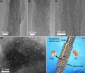
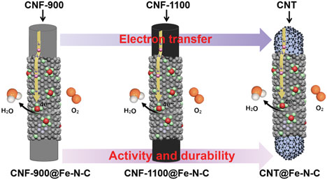
By using CNF-900, CNF-1100, and CNT as supports, we obtained three kinds of core–shell structured single-atom Fe catalysts, which are denoted as CNF-900@Fe–N–C, CNF-1100@Fe–N–C, and CNT@Fe–N–C. Figures 1(a)–1(c) show typical transmission electron microscopy (TEM) images of these catalysts. Clearly, all these materials have a similar one-dimensional core–shell structure. Compared with CNF-900@Fe–N–C and CNF-1100@Fe–N–C, CNT@Fe–N–C shows clearly resolved graphitic layers, indicative of a better crystallinity. The thickness of the shell is several nanometers and no nanoparticles are observed. Scanning TEM accompanied with the energy-dispersive spectrum images indicate that Fe, N, and C elements are uniformly distributed throughout the entire nanostructure (Fig. S3). These results suggest that elemental Fe may exist as isolated atoms. To further verify the presence of single Fe atoms, we utilized aberration-corrected scanning TEM to directly observe the CNT@Fe–N–C sample at atomic level. As shown in Fig. 1(d), abundant single Fe atoms are clearly observed as bright dots, indicating that our sample is a typical single-atom Fe catalyst. Figure 1(e) is a schematic showing the one-dimensional core–shell structured single-atom Fe catalysts. In an ORR process, electrons transfer to single-atom Fe-active sites distributed at the shell through an efficient electron transfer channel of the well-graphitized carbon support core and then an oxygen molecule gets four electrons to form water.
Typical TEM images of (a) CNF-900@Fe–N–C, (b) CNF-1100@Fe–N–C, and (c) CNT@Fe–N–C. (d) High-angle annular dark-field scanning TEM (HAADF-STEM) image of CNT@Fe–N–C, (e) schematic showing the ORR catalysis process of a core–shell structured Fe–N–C material.

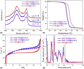
Figure 2(a) shows Raman spectra of the CNF-900@Fe–N–C, CNF-1100@Fe–N–C, and CNT@Fe–N–C catalysts. As we expected, the D-band and G-band peaks of these catalysts have similar line shapes, while the intensity ratio of D-band to G-band decreases in turn owing to the different graphitization degrees of carbon support cores, indicating that introduction of carbon supports with high crystallinity can improve the electrical conductivity of the final single-atom Fe catalysts obtained. This class of core–shell structured catalysts possesses a similar structure but different electrical conductivity, which is highly desired to study the effect of electrical conductivity on the ORR performance. Furthermore, TGA results show that the ORTs of CNF-900@Fe–N–C, CNF-1100@Fe–N–C, and CNT@Fe–N–C increase in sequence, which is consistent with Raman results. For the ORR, there are three important processes of mass transport, catalytic reaction, and electron transfer. Mass transport and catalytic reaction are dependent on the structure and active sites while electron transfer capacity is determined by electrical conductivity of an electrocatalyst. We designed three kinds of core–shell structured single-atom Fe catalysts with carbon supports having a similar shell structure but different crystallinities, aiming to study the effect of charge transfer on the ORR performance. The prerequisite of studying this effect is to keep other structural parameters including pore structure, specific surface area, and concentration of single-atom Fe-active sites as similar as possible.
(a) Raman spectra, (b) TGA curves, (c) N2 adsorption–desorption isotherm, and (d) corresponding pore size distributions of CNF-900@Fe–N–C, CNF-1100@Fe–N–C, and CNT@Fe–N–C.

To reveal the pore structure and specific surface area of these single-atom Fe catalysts, N2 adsorption–desorption measurements were performed. Figure 2(c) shows N2 adsorption–desorption isotherm curves of CNF-900@Fe–N–C, CNF-1100@Fe–N–C, and CNT@Fe–N–C. All these samples show a strong adsorption in the low-pressure (P/P 0 = 0–0.1) region, which is originated from abundant micropores. The Brunauer–Emmett–Teller surface area of CNT@Fe–N–C is 1140 m2/g, slightly lower than those of CNF-900@Fe–N–C (1401 m2/g) and CNF-1100@Fe–N–C (1408 m2/g). As shown in Fig. 2(d), these single-atom Fe catalysts have similar micropore and mesopore size distributions, which verifies that their pore structures are similar.
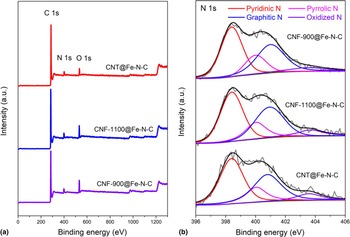
The components and chemical states of these single-atom catalysts were analyzed by x-ray photoelectron spectroscopy (XPS). Only C, N, and O signals are detected [Fig. 3(a) and Table S1], and no Fe signal is observed. The contents of Fe were determined to be 1.91, 1.84, and 1.92 wt.% in CNF-900@Fe–N–C, CNF-1100@Fe–N–C, and CNT@Fe–N–C, respectively, by ICP-MS. Figure (3b) shows high-resolution N 1s curves of CNF-900@Fe–N–C, CNF-1100@Fe–N–C, and CNT@Fe–N–C. Clearly, they have a similar N peak shape and similar ratio of pyridinic N (398.4 eV) doping configuration. Remarkably, the N 1s peak at 398.4 eV may also originate from Fe–Nx because of the small difference in the binding energies between Fe–Nx and pyridinic N. Based on the results of TEM, ICP-MS, and XPS characterizations, the three samples have a similar concentration of single-atom Fe-active sites. According to the above structure and composition analysis, it is clear that the CNF-900@Fe–N–C, CNF-1100@Fe–N–C, and CNT@Fe–N–C catalysts have a similar structure (one-dimensional core–shell structure, pore structure, and specific surface area) and composition (N-coordinated single-atom Fe sites) but different charge transfer capacities owing to the different electrical conductivities of carbon supports. These features make it possible to investigate the correlation between charge transfer and ORR performance of single-atom Fe catalysts.
(a) XPS survey spectra and (b) high-resolution N 1s curves of CNF-900@Fe–N–C, CNF-1100@Fe–N–C, and CNT@Fe–N–C.

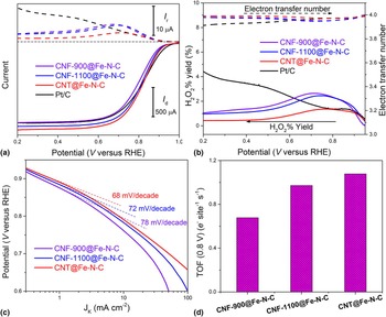
The electrocatalytic activity of these catalysts for the ORR was evaluated by RRDE measurements in an O2-saturated 0.1 M HClO4. As shown in Fig. 4(a), the CNT@Fe–N–PC catalyst shows the best ORR performance among these single-atom Fe catalysts, including largest half-wave potential and limiting current density. Compared with commercial Pt/C catalyst (20 wt.%, Alfa Aesar) with a standard loading of 0.1 mg cm, CNT@Fe–N–PC shows equal half-wave potential of 0.82 V and larger limiting current density, better than those of previously reported Fe–N–C catalysts (Table S2). Furthermore, CNF-1100@Fe–N–PC shows better ORR activity than CNF-900@Fe–N–PC. Figure 4(b) shows that the H2O2 yields of all these single-atom Fe catalysts at all potentials are <3%. The low H2O2 yield indicates that these catalysts have high catalytic efficiency for the ORR under acidic conditions and follow a complete four-electron-transfer pathway. Furthermore, the carbon supports also influence the yield of H2O2, e.g., better electrical conductivity leads to lower H2O2 yield. All these results suggest that the high electrical conductivity of carbon supports guarantees faster charge transfer, which improves the ORR efficiency.
(a) RRDE polarization curves and (b) peroxide yield and electron transfer number of CNF-900@Fe–N–C, CNF-1100@Fe–N–C, CNT@Fe–N–C, and Pt/C in an O2-saturated 0.1 M HClO4. (c) Tafel plots and (d) TOF of CNF-900@Fe–N–C, CNF-1100@Fe–N–C, and CNT@Fe–N–C.

To gain a better insight into the ORR catalysis mechanism, Tafel plots of the single-atom Fe catalysts were derived from the disk current [Fig. 4(c)]. The Tafel slope values of CNF-900@Fe–N–C, CNF-1100@Fe–N–C, and CNT@Fe–N–C are 78 mV/decade, 72 mV/decade, and 68 mV/decade, respectively. This result suggests that the first electron is likely the rate-determining step. Furthermore, with the increase of the electrical conductivity of single-atom Fe catalysts, the Tafel slope value gradually decreases. This indicates that higher electrical conductivity accelerates charge transfer and improves the ORR kinetics.[Reference Parimi, Umasankar, Atanassov and Ramasamy27] We also considered the quantification of TOF (number of electrons reduced per single-atom Fe-active site and per second at 0.8 V) based on kinetic current density and concentration of single-atom Fe-active sites.[Reference Jaouen and Dodelet28] Since no nanoparticles were detected in the catalysts, it is reasonable to assume that all the elemental Fe is in the form of isolated Fe atoms, and the concentration of single-atom Fe-active sites can be calculated from the mass fraction of Fe probed by ICP-MS. As shown in Fig. 4(d), the TOF (0.8 V) of CNT@Fe–N–C is 1.08 e−/site/s−1, which is ~1.6 times that of CNF-900@Fe–N–C (0.68 e−/site/s) and ~1.1 times of CNF-1100@Fe–N–C (0.94 e−/site/s). This suggests that fast charge transfer can boost the ORR activity of single-atom Fe-active sites. In particular, at negatively shifted potentials, the charge transfer becomes more significant in the ORR process. The TOF of CNT@Fe–N–C changes from 1.6 times of CNF-900@Fe–N–C at 0.8 V to ~2.2 times at 0.7 V [Fig. S4(a)] and ~4.4 times at 0.6 V [Fig. S4(b)].
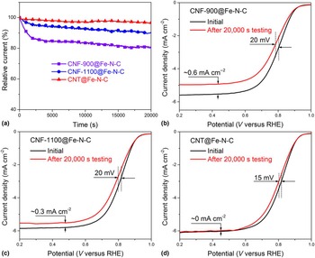
In addition to the ORR activity, we further studied the durability of these single-atom Fe catalysts. Figure 5(a) shows that the current density decay of CNT@Fe–N–C is 3.3% after 20,000 s of testing, much smaller than those of CNF-900@Fe–N–C (19.2%) and CNF-1100@Fe–N–C (9.6%), suggesting the high electrical conductivity of carbon supports can improve the ORR durability of single-atom Fe catalysts. The ORR polarization curves before and after 20,000 s testing are shown in Figs. 5(b)–5(d). We can see that the CNF-900@Fe–N–C catalyst [Fig. 5(b)] shows remarkable performance loss with a negative half-wave potential shift of 20 mV and limiting current density loss of 0.6 mA/cm2. Compared with CNF-900@Fe–N–C, CNF-1100@Fe–N–C [Fig. 5(c)] exhibits relatively better ORR durability (the limiting current density loss of 0.3 mA/cm2), however, poorer than that of CNT@Fe–N–C [Fig. 5(d)]. This further confirms that graphitized carbons can greatly increase the ORR durability.
(a) Chronoamperometric responses of CNF-900@Fe–N–C, CNF-1100@Fe–N–C, and CNT@Fe–N–C. The ORR polarization curves of (b) CNF-900@Fe–N–C, (c) CNF-1100@Fe–N–C, and (d) CNT@Fe–N–C before and after 20,000 s chronoamperometric responses.

The excellent ORR activity of these core–shell structured single-atom Fe catalysts is attributed to their unique structure, where the outer layer with single-atom Fe-active sites play a key role in catalyzing O2 reduction while inner graphitized carbon supports ensure fast charge transfer. Compared with traditional Fe–N–C materials, single-atom Fe catalysts have much higher concentration of ultrahigh-activity single-atom Fe sites and they need more robust support and better charge transfer ability. Highly efficient use of single-atom Fe-active sites can produce low H2O2 yield, which is beneficial to the ORR durability.[Reference Banham, Ye, Pei, Ozaki, Kishimoto and Imashiro29] Furthermore, robust supports have high corrosion resistance and are generally able to improve the ORR durability.[Reference Wu, More, Xu, Wang, Ferrandon, Kropf, Myers, Ma, Johnston and Zelenay30] Compared with CNFs, CNTs have better crystallinity and higher charge transfer ability. Thus, CNT@Fe–N–C shows the best ORR activity and durability.
In conclusion, we designed and prepared three one-dimensional core–shell structured catalysts with single-atom Fe-active sites on the outer layer and conductive CNF/CNT as inner support, aiming to study the effect of charge transfer on the ORR performance. Our results show that higher charge transfer ability of the carbon supports can greatly boost the ORR activity of single-atom Fe-active sites on the outer shell. Furthermore, the ORR durability is improved with the increase of graphitization degree of carbon supports. These results provide useful hints for the design and preparation of reliable and practical single-atom catalysts for the ORR and even other electrocatalytic processes.
Supplementary material
The supplementary material for this article can be found at https://doi.org/10.1557/mrc.2018.174
Acknowledgments
This work was supported by the Ministry of Science and Technology of China (Grant 2016YFA0200102), the National Natural Science Foundation of China (Grants 51625203, 51532008, 51521091, 51772303, 51572264), the Chinese Academy of Sciences (Grant KGZD-EW-T06), the CAS/SAFEA International Partnership Program for Creative Research Teams, and the Liaoning BaiQianWan Talents Program.