I. INTRODUCTION
In coming years, a primary objective of the nuclear energy industry will be to extend the lifetime of current reactor components to bridge the gap between present- and next-generation reactors (i.e., between Gen III reactor and Gen IV reactor concepts). Reference Grimes, Konings and Edwards1 A significant challenge during this time will be to develop nuclear fuels that are capable of safely achieving higher burn-ups with minimal performance degradation. In anticipation of this need, and with the continued development of next-generation nuclear fuel concepts, the response of fuel materials must be systematically characterized under the extreme conditions of intense irradiation, high temperature, and high stress. In these environments, there are dramatic changes in material properties, such as the development of new microstructures through polygonization and fission gas retention and release in the rim structure of high-burnup fuel pellets. Reference Rondinella and Wiss2
At present, the majority of postirradiation examination efforts on nuclear fuel and other nuclear materials involve techniques that are in general not suitable for atomic-level characterization. Examples of commonly used techniques include: Fluid-gravimetry and porosity measurements (density and swelling analysis), γ-scans and electron-probe microanalysis (EPMA) (fission product/elemental analysis), Raman spectroscopy, and an array of visual inspection methods, such as ceramography, scanning electron microscopy (SEM), brightfield transmission electron microscopy (TEM), and x-ray radiography. Reference Sah, Viswanathan, Ramadasan, Unnikrishnan and Anantharaman3–Reference Noirot, Desgranges and Lamontagne7 Due to the high level of radioactivity, current postirradiation examination efforts require expensive hot cells and dedicated handling facilities to provide sufficient shielding from the radiation, necessarily limiting the analytical methods that can be used for the characterization of nuclear fuel.
High-resolution structural and chemical analysis of microgram samples is now possible due to the widespread availability of third generation synchrotron sources. In recent years, there has been a renewed interest in using synchrotron radiation (SR) to characterize actinides and radioactive compounds with several dedicated synchrotron beamlines around the world, Reference Shi, Yuan, Wang, Wang, Mei, Xiao, Zhang, Li, Zhao and Chai8–Reference Matz, Schell, Bernhard, Prokert, Reich, Claußner, Oehme, Schlenk, Dienel, Funke, Eichhorn, Betzl, Prühl, Strauch, Hüttig, Krug, Neumann, Brendler, Reichel, Denecke and Nitsche13 such as the MARS beamline at the French National Synchrotron Facility SOLEIL in Paris, France and the BL-27 beamline at the Photon Factory in Tsukuba, Japan. Examples of applying SR to nuclear materials characterization include, but are not limited to x-ray diffraction (XRD), small-angle x-ray scattering (SAXS), and extended x-ray absorption fine structure (EXAFS) to evaluate void, strain, and coordination evolution in irradiated and unirradiated structural-component materials. Reference Pan, Wu, Mo, Chen, Almer, Ilavsky, Haeffner and Stubbins14–Reference Kuri, Cammelli, Degueldre, Bertsch and Gavillet17 XRD and x-ray absorption near-edge spectroscopy (XANES) are applied to study corrosion- and phase-kinetics in cladding materials. Reference Daum, Chu and Motta18–Reference Polatidis, Frankel, Wei, Klaus, Comstock, Ambard, Lyon, Cottis and Preuss20 Synchrotron studies on irradiated nuclear fuels are limited to dedicated research groups Reference Shi, Yuan, Wang, Wang, Mei, Xiao, Zhang, Li, Zhao and Chai8,Reference Mieszczynski, Kuri, Degueldre, Martin, Bertsch, Borca, Grolimund, Delafoy and Simoni21–Reference Ice and Specht24 that have overcome the handling issues associated with highly radioactive fuel materials. There are several advantages to the use of SR for structural- and chemical postirradiation examination studies. X-ray scattering of polycrystalline materials yields measurements that are more statistically reliable than electron microscopy techniques, for example, which limit observations to a very small region of interest. Synchrotron techniques are also flexible in terms of x-ray energy and detector selection/configuration, permitting multiscale (nm–μm) characterization for specific elements, phases, and defects.
The application of ion beams is important for the study of radiation effects in nuclear materials, as it allows the “tuning” of radiation energy, particle mass, fluence, and temperature to probe specific defect mechanisms of interest at ambient and elevated pressures. Reference Was, Averback and Konings25 Adjusting ion velocities from fission-fragment energies (80–120 MeV) to very high energies (1–3 GeV), for example, begins to decouple the effects of electronic and nuclear energy deposition mechanisms. The ability to isolate defect mechanisms is crucial to the study of complex irradiation-damage problems where there exist both competing and synergistic contributions from the irradiation environment of temperature and stress. Energetic heavy ions deposit energy in matter predominantly by interactions with the target electrons, inducing excitations and ionization along the ion path. The energy is subsequently transferred to the atomic structure, mainly via nonradiative decay of electrons coupled with phonon emission. In many solids (predominantly in insulators), cylindrical damage zones, so-called ion tracks, are created if the energy deposition to the atoms is sufficiently high. Reference Toulemonde, Assmann, Dufour, Meftah, Studer, Trautmann and Sigmund26
High-resolution TEM Reference Zhang, Lang, Ewing, Devanathan, Weber and Toulemonde27–Reference Li, Kluth, Schauries, Rodriguez, Lang, Zhang, Zdorovets, Trautmann and Ewing30 and SAXS Reference Afra, Lang, Rodriguez, Zhang, Giulian, Kirby, Ewing, Trautmann, Toulemonde and Kluth31–Reference Rodriguez, Li, Chen, Trautmann, Bierschenk, Afra, Schauries, Ewing, Mudie and Kluth33 are important techniques to characterize individual ion tracks, providing direct atomic-scale information on the size and damage morphology. Laboratory XRD is used to obtain information on the long-range order of irradiated materials. Some ion-accelerator facilities are equipped with dedicated diffractometer beamlines for in situ measurements as a function of increasing fluence. Reference Hémon, Dufour, Berthelot, Gourbilleau, Paumier and Bégin-Collin34–Reference Lang, Zhang, Li, Severin, Bender, Klaumünzer, Trautmann and Ewing37 Synchrotron-based techniques are much less frequently applied to study ion-beam induced material modifications. Reference Afra, Lang, Rodriguez, Zhang, Giulian, Kirby, Ewing, Trautmann, Toulemonde and Kluth31–Reference Rodriguez, Li, Chen, Trautmann, Bierschenk, Afra, Schauries, Ewing, Mudie and Kluth33,Reference Studer, Houpert, Toulemonde and Dartyges38–Reference Tahara, Shimizu, Ishikawa, Okamoto, Hori, Matsui and Iwase42 However, the very high penetration depth of energetic heavy ions (typically 10–100 µm) allows the use of SR in transmission mode for systematic characterization of structural and electronic material modifications over the entire irradiated sample volume. Intense synchrotron x-ray beams coupled with their high resolution are particularly useful for irradiation effects that are not associated with continuous, fully modified ion tracks, such as isolated defects, defect clusters, discontinuous damage domains, and structural transformations from multiple ion impacts. This type of radiation damage is accessible by XRD and XAS measurements as a function of increasing ion fluence. Most importantly, SR characterization is compatible with simultaneous coupling with heatable, high-pressure apparatuses. The application of high temperature and/or high pressure to irradiated and nonirradiated materials in combination with in situ SR investigation extends characterization capabilities in phase space and enables time-resolved measurements of defect production and recovery kinetics. This allows, for example, the analysis of samples irradiated in situ under high pressure Reference Lang, Zhang, Zhang, Wang, Schuster, Trautmann, Neumann, Becker and Ewing43,Reference Lang, Zhang, Lian, Trautmann, Neumann and Ewing44 to obtain information on unstable phases that form under coupled extreme conditions, which are not recoverable to ambient conditions. We describe in detail the advantages of analyzing irradiated nuclear materials using synchrotron x-ray techniques. The use of high-resolution microdiffraction together with a specially designed holder system allows for the use of radioactive sample volumes that are sufficiently small to eliminate the need for extensive radiation shielding. After introducing the experimental procedure of sample preparation, irradiation, and synchrotron x-ray characterization, we demonstrate how this approach is applied to study a number of ion-induced material modifications: Defect formation, amorphization, and crystalline-to-crystalline transformation. Finally, the use of a heatable high-pressure cell is described as a new means for the investigation of the behavior of irradiated nuclear materials under well-controlled high-temperature and/or high-pressure conditions.
II. SAMPLE PREPARATION AND ION-BEAM EXPERIMENTS
Most of the investigated materials, in particular complex ceramics (e.g., A2B2O7) and simple actinide oxides (e.g., ThO2), were synthesized or purchased as polycrystalline samples with a grain size on the order of 1 μm. The use of these materials is ideal for synchrotron powder XRD experiments with focused x-ray beams because it minimizes grain-orientation effects. The ion irradiation of microgram powders of nuclear materials and subsequent characterization by means of SR experiments requires a specially designed holder system. Adopted from the small sample volumes that are characteristic of high-pressure experimental procedures, microscopic sample chambers are prepared in a thin molybdenum foil (Thermo Shield, dimensions 2 × 20 mm2) by drilling several holes with a diameter of ∼100 μm. The foil thickness varies from 12.5 to 50 μm and is chosen to match the ion-beam energy to allow full penetration of the sample pellets. For heavy ions, this requires a specific energy of about 1, 5, and 10 MeV/u for 12.5, 25, and 50 μm thick samples, respectively. A tabletop electric-discharge machining device from Hylozoic Micro EDM System equipped with a 100 μm copper wire tip is used to drill holes through the molybdenum foils (Fig. 1). Sample chambers are cleaned in an ultrasonic bath with acetone, and the sample powder is placed over the holes and pressed between two steel die-pieces in a hydraulic laboratory press (Carver, Inc.) using loads up to ∼9 tons. Excess sample material is then removed with a sharp scalpel under the microscope to ensure well-defined pellet dimensions of 100 μm in diameter and 12.5, 25, or 50 μm in thickness depending on the applied ion energy. Typically, a sample prepared for a given irradiation fluence consists of seven small pellets (filled holes). The large number of pellets is critical to account for losses during ion irradiation and handling at the synchrotron facility. Several sample sets of various materials are prepared on a rectangular molybdenum-foil strip (Fig. 2), spaced in an equidistant manner to ensure identical irradiation conditions for comparative studies.
Sequence of the sample preparation for ambient ion-irradiation experiments. Microscopic holes (diameter: ∼100 µm) are drilled into a molybdenum foil of typical 12.5–50 µm thickness (area: 2 × 20 mm2) serving as sample chambers. The sample pellets are then prepared by pressing loose powder into the cleaned holes and scraping off any excess material.

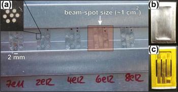
(a) Photograph of irradiation holder with five sets of samples to be exposed to fluences between 7 × 10¹¹ and 8 × 10¹² ions/cm2. Three molybdenum strips, each with two sets of seven pellets, are irradiated simultaneously with an ion beam of ∼1 cm2 spot size. The inset displays the seven symmetrically arranged pellets of the same material (diameter: ∼100 µm). To avoid beamline contamination by radionuclides or activated materials, the thin metal foils are attached to small aluminum frames (area: 1 × 2 cm2) covered with (b) 10 µm aluminum foil for ion-beam irradiation and (c) with 25 μm Kapton foil for synchrotron x-ray measurements.

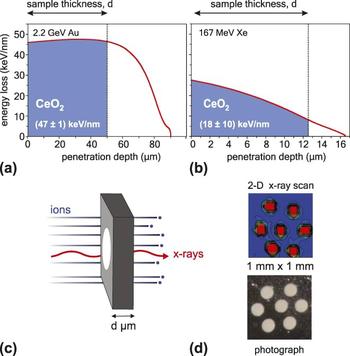
With a typical ion-beam spot size of ∼1 cm2 and appropriate spacing between holders intended for individual fluence steps, three molybdenum strips with pellets can be placed in the ion beam and simultaneously irradiated to the same fluence. The molybdenum foils are directly fixed with two-sided tape onto a larger metal plate serving as a sample holder in the irradiation chamber [Fig. 2(a)]. Alternatively, the strips can be attached in sets of three to smaller aluminum-holder frames, which are mounted to the larger irradiation holder. The latter procedure has the advantage that the thin molybdenum strips with fragile pellets are permanently fixed for ion irradiation and synchrotron characterization. In addition, the aluminum holders can be individually wrapped with a thin aluminum foil [typical thickness: 10 μm; Fig. 2(b)] prior to irradiation to prevent inadvertent beamline contamination in the case of ion-beam induced fragmentation. For characterization at the synchrotron facility, the aluminum foil is replaced by a thin, x-ray transparent Kapton foil [typical thickness: 25 μm; Fig. 2(c)]. Independent of the holder system, each set of samples is homogeneously irradiated with the same ion beam to a desired fluence [see indicated beam-spot size in Fig. 2(a)]. The irradiation is conducted at room temperature under normal beam incidence. Fluences are typically applied in ∼10 steps between 1 × 10¹⁰ and 5 × 10¹³ ions/cm2. Irradiation experiments are performed at beamline M1 of the UNILAC linear accelerator at the GSI Helmholtz Center for Heavy Ion Research in Darmstadt, Germany and at the IC-100 cyclotron at the Joint Institute for Nuclear Research in Dubna, Russia. Simultaneous irradiation of six samples with identical beam settings reduces the relative fluence uncertainty, thus increasing the consistency in direct comparison of their radiation responses. When using high beam energies (e.g., 11.1 MeV/u), all ions completely penetrate the sample pellets and deposit an almost constant electronic energy loss, dE/dx, throughout the entire sample thickness. Reference Lang, Zhang, Zhang, Tracy, Cusick, VonEhr, Chen, Trautmann and Ewing45 The ion range and dE/dx for a specific sample and beam configuration are determined by the SRIM code. Reference Ziegler, Ziegler and Biersack46 However, it has to be considered for the applied sample configuration that the pellets are prepared with a mechanical press, operating at low pressure, without subsequent sintering. The pellets have densities that are significantly lower than the theoretical value. For a similar sample preparation using powdered actinide oxides prepared by cold pressing to comparable loads, the actual pellet density did not exceed 60% of the theoretical value. Reference Luther, Necker, Mihaila, Papin and Guidry47 To account for the reduced density in the sample pellets (assuming 60% of theoretical density), the ion-range data from SRIM calculations performed with theoretical density are scaled by a factor of 1.66. This approach is used instead of performing the SRIM calculations with reduced density because the loose packing of the sample pellets (“empty space”) only increases the ion range, but does not influence the energy loss per unit length, dE/dx, within the typically micrometer-sized polycrystalline sample grains of approximately theoretical density. As an example, the range-correction procedure implies that 2.2 GeV Au ions lose about 1.45 GeV of kinetic energy in 50 µm thick CeO2 pellets [Fig. 3(a)]. The nuclear energy loss at such high energies is at least three orders of magnitude lower than the electronic dE/dx. The variation of the electronic energy loss throughout the entire sample thickness is, for GeV ions, typically below 5%. The situation is different for lower beam energies (e.g., 1.3 MeV/u). The use of thinner molybdenum foils enables ions to fully penetrate the sample pellets; however, the dE/dx shows considerable variation throughout the entire sample thickness, as shown in Fig. 3(b) for 167 MeV Xe ions incident on a 12.5 µm thick CeO2 sample. The range-correction procedure implies that these ions lose about 100 MeV of kinetic energy in the sample pellets with an electronic dE/dx that is still one order of magnitude higher than the nuclear component when completely traversing the sample thickness. By varying both beam energies and sample thickness, the contributions of electronic and nuclear dE/dx on radiation effects can be studied over a wide range of conditions. This is particularly important for the investigation of radiation damage from fission fragments, which experience a considerable variation in stopping power along their trajectories. After irradiation and SR measurements, the samples are further analyzed by complementary characterization techniques, such as micro-Raman spectroscopy and TEM. In the case of TEM, the homogenously irradiated pellets are pushed out of the metal foils with a sharp needle, ground into a powder, and are dispersed onto holey carbon film supported TEM grids. Reference Zhang, Lang, Ewing, Devanathan, Weber and Toulemonde27–Reference Li, Kluth, Schauries, Rodriguez, Lang, Zhang, Zdorovets, Trautmann and Ewing30
(a) Energy loss curve displays 50 μm thin CeO2 exposed to 2.2 GeV Au ions inducing an almost constant energy loss of 47 ± 1 keV/nm. (b) Irradiation of 12.5 μm thin CeO2 with 167 MeV Xe ions leads to an energy loss with larger variation throughout the sample thickness of 18 ± 10 keV/nm. (c) Schematic illustration of ion-irradiated samples analyzed by synchrotron-XRD. Energetic heavy ions completely penetrate the (white) powder sample pressed into a thin molybdenum foil (diameter: 100 μm, thickness: (a) 50 μm and (b) 12.5 μm). The ion beam and the x-rays are collinear, but the spot size of the focused x-ray beam is significantly smaller than the size of the pellet (spot size of ion beam ∼1 cm2, see Fig. 2). Powder XRD experiments at a synchrotron source are used to study ion-induced structural modifications throughout the sample thickness. (d) Two dimensional x-ray scans can be used to image the sample pellets within the molybdenum foil and align the x-ray beam to the sample position. The x-ray absorption of the pellets is lower than that from the surrounding molybdenum holder as indicated by the transmitted x-ray intensity (red: high intensity versus blue: low intensity).

III. SYNCHROTRON X-RAY CHARACTERIZATION
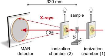
After irradiation, each holder is examined using an optical microscope. Particularly at high fluences, radiation-induced dimensional changes of the pellets (e.g., volume reduction due to densification) or fragmentation result in sample loss. This depends on the particular sample type, hole-size, and ion-beam settings (e.g., beam flux); however, there is usually sufficient material remaining to be analyzed at the synchrotron facility. Due to the small x-ray beam size, even minor sample residue at the edge of the drilled hole is sufficient for investigation. Synchrotron x-ray analysis of irradiated materials is performed at the Advanced Photon Source (APS) of Argonne National Laboratory. Two high-pressure sectors—sector 16 (HPCAT, High-Pressure Collaborative Access Team) and sector 13 (GSECARS, GeoSoilEnviro Center for Advanced Radiation Sources)—provide high-brilliance, hard x-rays from this third-generation synchrotron light source for which all of the principal synchrotron-based analytical techniques are available. Highly focused x-ray beams (spot size between 3 and 25 µm) are conventionally used to study microscopic high-pressure samples. This makes these x-ray beamlines ideal analytical tools for the investigation of irradiated nuclear materials with microgram sample quantities. As an example, beamline HPCAT 16 BM-D is used to explain the operational mode of a typical synchrotron high-pressure beamline (Fig. 4). The monochromatic x-ray wave length is adjustable by a Si(111) double-crystal monochromator operating in pseudo channel-cut mode (typical value: λ = 0.4959 Å or E = 25.000 keV). The incident beam size before the monochromator is 1.5 mm with a beam-slit location of ∼42 m from the source. This configuration results in an energy resolution of about ΔE/E = 5 × 10⁻⁴ at E = 25.000 keV. The downstream x-ray beam behind the monochromator is further focused using a Rh-coated Kirkpatrick–Baez (KB) type mirror at 1.5 mrad angles (cut-off energy is ∼45 keV) in vertical and horizontal directions. The asymmetry of both focusing mirrors leads to a beam profile at the focal point of about 16 × 6 µm in the FWHM. The converging incident beam is constrained by a clean-up pinhole of 35 μm in diameter just in front of the sample station to cut out the scattering background from nearby material hit by the x-ray beam. The total intensity on the sample from a focused beam is typically 5 × 10⁸ photons/s. The structure of irradiated materials is investigated by means of angle-dispersive microXRD. Debye–Scherrer rings are collected using a MAR345 Image Plate detector (Fig. 4) that is typically located 320 mm behind the sample position. The detector geometry and distance from the sample are calibrated using a National Institute of Standards and Technology (NIST) CeO2 standard powder. The electronic configuration of the irradiated materials is investigated by means of x-ray absorption spectroscopy (XAS). These measurements can be combined with XRD measurements by the switchable diffraction–absorption setup without losing the sample alignment. The double crystal monochromator is designed for a nearly fixed-exit configuration (from 6 to 60 keV energy), which allows switching from the XRD to the XAS setup by simply moving to the designated absorption edge energy and tweaking the second monochromator crystal to maximize the beam intensity after the clean-up pinhole. The monitor and detector ionization chambers are pneumatically moved into position (Fig. 4), and the energy is scanned based on predefined tabulated energy points. For the high-energy absorption measurement, the two ionization-chambers are filled with pure Ar gas flowing with a pressure slightly above atmosphere. This switchable micro-XRD-XAS setup is unique in that both techniques can be applied to an identical sample volume to obtain quasi-simultaneous structural and electronic information on irradiated materials, as is required for the systematic study of nuclear material radiation responses.
Schematic illustration of beamline HPCAT 16 BM-D at the APS of Argonne National Laboratory. The monitor (1) and detector (2) ionization chambers are pneumatically moved into position for XAS measurements, or removed for XRD experiments using a MAR345 image plate detector. The switchable micro-XRD-XAS setup allows one to use the techniques quasi-simultaneous to obtain structural and electronic information within identical sample volumes. The typical sample–detector distance of 320 mm leads, with x-rays of wave length 0.4959 Å, to a maximum 2θ value of ∼30° at the two-dimensional MAR detector.

The small sample pellets are initially aligned with respect to the x-ray beam with an optical microscope mounted at the beamline. Fine adjustment with accuracy at the µm-level is obtained by scanning the beam horizontally and vertically across the sample and monitoring its intensity with a photodiode (sample stage is moved with respect to stationary x-ray beam). The center position of the sample pellet is located by the differences in x-ray absorption of the sample and molybdenum holder. Extended two-dimensional scans are also available with x-ray intensity maps reproducing accurately the sample-pellet configuration within the molybdenum foil [Fig. 3(d)]. The focused x-ray beam can then be directed to the center of the sample pellet (or any desired location within the sample). As a final step, the sample position with respect to the detector—crucial for an accurate determination of the unit cell constants—must be adjusted to the previously calibrated distance. For this purpose, the sample is moved to the axis of rotation, the focal point of the x-ray beam. This can be completed by repeated horizontal scans of x-ray absorbance at different angles ω of rotation (Fig. 4).Only at the rotation axis are the horizontal scans identical at any given angle and, if they deviate, the sample–detector distance is adjusted by moving the sample relative to the detector. By repeating this procedure several times, the sample position can be determined with an accuracy of ±10 µm.
After exposure of a MAR345 detector to the diffracted x-rays for collection times ranging from seconds to minutes, the resulting diffraction images are integrated into 2θ-intensity profiles (XRD patterns) with the Fit2d software. Reference Hammersley, Svensson, Hanfland, Fitch and Häussermann48 Depending on the type of ion-induced material modification, XRD patterns are analyzed by Rietveld refinement to obtain unit-cell parameters of defective materials, establish phase fractions from irradiation-induced crystalline-to-crystalline transformations, or measure other modifications, such as changes in grain size or heterogeneous microstrain. For example, changes in unit-cell volume, indicated by shifts in the diffraction angles of maxima, can be caused by the accumulation of Frenkel pairs, as both vacancy and interstitial defects occupy volumes distinct from those typical of atoms in their ideal sites. Changes in grain size or the production of heterogeneous microstrain can induce broadening of diffraction peaks, which can also be quantified via refinement. Reference Williamson and Hall49,Reference Tracy, Pray, Lang, Zhang, Popov, Park, Trautmann, Bender, Severin, Skuratov and Ewing50 Grain-size reduction and grain growth can both occur in irradiated ceramics, with the former indicating fragmentation or polygonization of crystallites. Microstrain is often concomitant with point defect-induced unit cell expansion, as the incorporation of interstitial and vacancy defects with distinct volumes leads to distortions in the local structure of the material. In some cases, it may be possible to determine the character of defects or defect clusters based on their influence on diffraction peak positions, breadths, and intensities, along with refinement of the occupancies of atomic sites (to identify the presence of a high concentration of vacancies or interstitials on such sites). Reference Weber51 However, such analysis is often hindered by the large difference in mass (and therefore x-ray scattering strength) between the cations and anions of actinide materials. In these cases, occupancies of anion sites cannot be accurately resolved, as their contribution to the overall scattering of these materials is relatively small. The use of a two-dimensional detector for transmission-based XRD experiments provides additional information on sample texture and strain. It allows for azimuthal resolution of the intensity, breadth, and position of individual diffraction maxima, which provides information on the orientation dependence of radiation-induced structural modifications. The amorphization process in irradiated nuclear materials can be investigated by applying appropriate peak-fitting procedures for deconvoluting the contribution of the crystalline (sharp diffraction maxima) and amorphous (broad diffuse scattering) sample fractions to the XRD patterns. Reference Lang, Zhang, Lian, Trautmann, Wang and Ewing52 The XAS spectra are analyzed for changes in the shape or position of the absorption edges and associated features. Shifts in edge energies can indicate changes in the oxidation state of an element, while changes in pre- or postedge features are often indicative of changes in the local coordination environment of atoms. Both can be caused by irradiation, with the latter providing information complementary to that of XRD analysis, as Frenkel pair production entails modification of the coordination of both displaced atoms and those adjacent to defect sites. In all cases, comparison of patterns with standards, for example, materials in which the element of interest is known to exhibit specific oxidation states, is useful, considering the difficulties associated with modeling of core electron absorption spectra. The following section gives examples of different types of ion-induced material modifications and shows how synchrotron x-ray techniques can be applied to their characterization.
IV. ION-INDUCED MATERIAL MODIFICATIONS
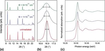
An important application of the described synchrotron approach is the characterization of defect formation in actinide oxides and analog materials (e.g., ThO2, UO2, and CeO2). The high x-ray energies together with state-of-the-art image plates or CCD detectors allow for good angular resolution in the collected XRD patterns, which is critical for the detection of small unit-cell parameter changes resulting from the accumulation of simple point defects or small defect clusters. As an example, Fig. 5 shows stacked XRD patterns of ThO2 before and after irradiation with 950 MeV Au ions. With increasing irradiation fluence, Φ, three modifications can be observed in the patterns Reference Tracy, Pray, Lang, Zhang, Popov, Park, Trautmann, Bender, Severin, Skuratov and Ewing50 : (i) shifts of all fluorite-structure diffraction maxima to lower 2θ values, (ii) peak broadening, and (iii) a reduction in the intensity of the diffraction maxima. The small peak shifts indicate an increase in the average unit-cell parameter, while the intensity reduction suggests a decrease in the number of scattering atoms occupying the ideal fluorite-structure atomic positions, resulting in a partial loss of coherent Bragg x-ray scattering. Unit-cell parameters of ThO2 from irradiation-induced defect accumulation were determined by Rietveld refinement as a function of increasing fluence and revealed a maximum increase of Δa/a = 0.049 ± 0.002%. Reference Tracy, Pray, Lang, Zhang, Popov, Park, Trautmann, Bender, Severin, Skuratov and Ewing50,Reference Tracy, Lang, Pray, Popov, Park, Trautmann and Ewing53 This value is approximately one order of magnitude less than those obtained by Weber Reference Weber51 for alpha-particle irradiations of the similar fluorite materials CeO2, UO2, and PuO2. This suggests that damage production by swift heavy ions in fluorite oxides is much less efficient than that of alpha particles, whose energy deposition is characterized by a significant nuclear energy loss component and less heating of the material in the damage cascade region. However, two-orders of magnitude higher alpha fluences are required to reach the maximum unit-cell parameter increase. The small unit-cell parameter changes of well below 0.1% in the case of swift heavy ions demonstrate the high resolution of synchrotron x-ray measurements, which are able to detect minor peak position and shape changes in irradiated materials [Fig. 5(b)]. The initially sharp diffraction maxima from synchrotron XRD patterns allow the detection of small peak-width changes after irradiation. Williamson–Hall analysis of the angular dependence of diffraction peak breadth increases Reference Williamson and Hall49 showed that the irradiation-induced peak broadening in ThO2 is caused primarily by the accumulation of localized, heterogeneous microstrain, which becomes larger with increasing ion fluence without showing a systematic variation in grain size. Reference Tracy, Pray, Lang, Zhang, Popov, Park, Trautmann, Bender, Severin, Skuratov and Ewing50 The XAS measurements on the same set of irradiated samples [Fig. 5(c)] show no change in the electronic structure of ThO2 or in the local bonding environment of the Th cation. This technique is sensitive to the valence state of the cation and its electronic configuration. The lack of modification to the Th L III-edge in the form of either an energy shift or a change in the edge shape indicates that its chemical state is largely maintained despite the production of defects.
(a) Representative XRD patterns of irradiated (950 MeV Au ions) and unirradiated ThO2. (b) Shifts to lower 2θ values, broadening, and a decrease in the intensity of all diffraction maxima occur with increasing ion fluence. The vertical lines show the diffraction maximum before (solid) and after (dotted) exposure to the maximum ion fluence, indicating an increase in the unit-cell parameter. The horizontal arrows correspond to the FWHM of the peaks. (c) XAS spectra of the Th L III edge of irradiated and unirradiated ThO2 (same fluence values as in (a)). No change in the shape or position of the absorption edge is observed, suggesting that the electronic structure of ThO2 is not significantly modified by swift heavy ion irradiation. This figure was modified from Ref. Reference Tracy, Pray, Lang, Zhang, Popov, Park, Trautmann, Bender, Severin, Skuratov and Ewing50.

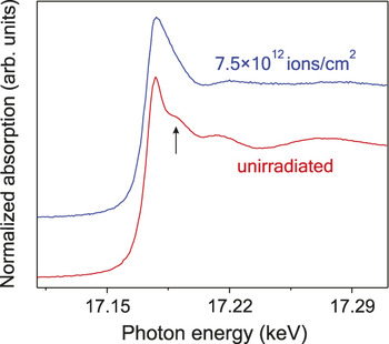
This is in contrast to the analog oxide CeO2, for which distinct redox changes of the Ce cation have been observed after ion irradiation. Reference Ohno, Iwase, Matsumura, Nishihata, Mizuki, Ishikawa, Baba, Hirao, Sonoda and Kinoshita39,Reference Iwase, Ohno, Ishikawa, Baba, Hirao, Sonoda and Kinoshita40,Reference Tracy, Lang, Pray, Popov, Park, Trautmann and Ewing53 Modifications in the electronic configuration after irradiation have also been found in uranyl hydroxide, UO2(OH)2, irradiated with swift heavy ions (Fig. 6). The edge shape and postedge features in the U L III-edge XAS spectra show significant changes after irradiation with 950 MeV Au ions. Reference Tracy, Lang, Pray, Popov, Park, Trautmann and Ewing53 These data are consistent with a loss of the initial uranyl local structure and changes to the oxidation state of uranium. Reference Helean, Navrotsky, Vance, Carter, Ebbinghaus, Krikorian, Lian, Wang and Catalano54 Irradiation to a fluence of 7.5 × 10¹² ions/cm2 is sufficient to change considerably the ratio of hexavalent-to-tetravalent uranium, which leads to significant changes in the long-range structure as evidenced by XRD measurements (not shown here). This example, which is described in detail elsewhere, Reference Tracy, Lang, Pray, Popov, Park, Trautmann and Ewing53 shows that combining XRD and XAS measurements over the same sample volume is a powerful approach to accurately identify coupling between the electronic and atomic structures of irradiated nuclear materials.
U L III edge XAS spectra for uranyl hydroxide, (UO)2OH, before and after irradiation with 950 MeV Au ions to a fluence of 7.5 × 1012 cm−2. The initial spectrum (unirradiated) is characteristic of hexavalent uranium in a uranyl coordination complex. The shoulder of the edge at approximately 17.19 eV (see arrow) is a multiple-scattering resonance feature arising from the uranyl axial oxygen atoms. After irradiation, this feature is attenuated and significant broadening of the edge peak (white line) is observed. These changes are consistent with irradiation-induced loss of the uranyl coordination and concomitant reduction in the oxidation state of uranium.

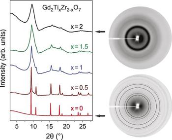
Synchrotron XRD is also a very powerful technique to investigate crystalline-to-amorphous transformations, which are induced in many complex oxides by ion irradiation. The intense x-ray beam is ideal to characterize the weakly scattering noncrystalline phase as shown for the Gd2Ti x Zr2−x O7 pyrochlore binary in Fig. 7. Reference Lang, Zhang, Lian, Trautmann, Wang and Ewing52 The sequence of synchrotron XRD patterns from different sample compositions irradiated with 1.43 GeV Xe ions (fluence: 1 × 10¹³ ions/cm2) displays two broad peaks from amorphous domains that increasingly dominating the pattern as Zr is substituted by Ti (bottom to top). As compared with laboratory x-ray measurements of the same pyrochlore compositions, Reference Sattonnay, Moll, Thomé, Decorse, Legros, Simon, Jagielski, Jozwik and Monnet55 the amorphous phase has intense diffraction maxima in synchrotron XRD patterns with a relatively high signal-to-noise ratio. The diffraction image of Gd2Ti2O7 pyrochlore shows the diffuse and broad, yet intense first-order amorphous diffraction maximum (Fig. 7, right top). The contributions of crystalline and amorphous sample fractions can be determined from XRD patterns by means of a deconvolution procedure and peak-fitting. This analytical method, which is described in detail elsewhere, Reference Lang, Zhang, Lian, Trautmann, Wang and Ewing52 is based on the relative integrated intensities of the amorphous and crystalline peaks over a measured 2θ range. Thus, the ratio of the amorphous-to-crystalline fraction does not depend on x-ray beam intensity, exposure time, and sample properties (e.g., thickness and density). This approach is essential for synchrotron-based XRD measurements using transmitting x-rays and pressed powders, as variations in sample thickness and density affect the overall peak intensities. An alternative method was used by Sattonnay et al. Reference Sattonnay, Moll, Thomé, Decorse, Legros, Simon, Jagielski, Jozwik and Monnet55 for the quantitative description of irradiation-induced amorphization in the same pyrochlore system based on laboratory x-ray measurements (intensity reduction of only crystalline diffraction maxima). In either case, the obtained experimental data as a function of increasing fluence in combination with appropriate damage models (e.g., single-impact model Reference Weber56 ) allow the determination of the amorphization cross-section (and effective track diameter) for a given sample composition Reference Lang, Zhang, Lian, Trautmann, Wang and Ewing52,Reference Sattonnay, Moll, Thomé, Decorse, Legros, Simon, Jagielski, Jozwik and Monnet55 and a specific ion projectile. Reference Lang, Toulemonde, Zhang, Zhang, Tracy, Lian, Wang, Weber, Severin, Bender, Trautmann and Ewing57 Systematic synchrotron x-ray measurements reveal the wide range of behavior of the Gd2Ti x Zr2−x O7 pyrochlore system in response to swift heavy ion irradiation as a function of composition. The results are in agreement with data from keV–MeV ion-beam irradiations, for which the nuclear collisions dominate the damage production process. Reference Begg, Hess, McCready, Thevuthasan and Weber58 The increased radiation resistance of Zr-rich pyrochlore compositions is explained as being the result of a decreasing ratio of the radii of the A- and B-site cations, r A/r B, leading to increased stability of the defect-fluorite structure. The XRD image of Gd2Zr2O7 (Fig. 7, right bottom) shows no evidence of amorphization after irradiation with 1 × 10¹³ Xe ions/cm2 and only the sharp diffraction maxima of the disordered, defect-fluorite structure are present.
(left) XRD patterns of five pyrochlore compositions of the Gd2Ti x Zr2−x O7 binary after irradiation with 1.43 GeV Xe ions to the same fluence of 1 × 1013 cm−2. The two broad peaks from amorphous domains increasingly dominate the pattern as Zr is substituted by Ti (bottom to top). Only for Gd2Zr2O7 the peaks remain sharp without a broad diffuse background indicative that no amorphization has occurred. (right, bottom) Detector images from the irradiated end-member pyrochlores show diffraction rings typical of the defect-fluorite structure for Gd2Zr2O7, while (right, top) Gd2Ti2O7 shows broad diffuse scattering due to the amorphous phase. This figure was modified from Ref. Reference Lang, Zhang, Lian, Trautmann, Wang and Ewing52.

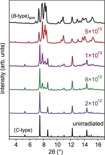
Ion irradiation commonly leads to amorphization, disordering, and formation of simple defects or defect clusters; however, ion-beam exposure can also cause crystalline-to-crystalline structural transformations to high-temperature or high-pressure phases. Reference Benyagoub35 Synchrotron XRD measurements are very appropriate for the study of such phase transformation, as they provide detailed information on the sample structure and proportions of the resulting phases. Selected XRD patterns of Gd2O3 before and after irradiation with increasing fluence (bottom-to-top) are shown in Fig. 8. Reference Lang, Zhang, Zhang, Tracy, Cusick, VonEhr, Chen, Trautmann and Ewing45 The diffraction maxima of the initial cubic structure gradually decrease in intensity as a function of ion fluence, concurrent with the in-growth of several new diffraction peaks. According to Rietveld refinement, the new diffraction maxima are from a monoclinic high-temperature phase. Similar measurements on swift heavy ion irradiated Y2O3 using a laboratory x-ray spectrometer could not resolve the individual peaks from the cubic and monoclinic phase appearing at 2θ values between 7 and 9°, Reference Hémon, Chailley, Dooryhée, Dufour, Gourbilleau, Levesque and Paumier59 thus demonstrating the advantage to use high-resolution synchrotron x-ray measurements. Depending on the material, ion-beam induced crystalline-to-crystalline transformation pathways can be characterized by a single (e.g., Y2O3, Ref. Reference Hémon, Dufour, Gourbilleau, Paumier, Dooryhée and Bégin-Colin60) or a multiple (e.g., ZrO2, Ref. Reference Benyagoub35) ion-impact mechanism. Similar results have been found for low-energy ions but at significantly higher fluences. Reference Tang, Lu, Valdez and Sickafus61
Synchrotron XRD patterns of Gd2O3 before and after irradiation with 2.2 GeV Au ions (fluence values are given in ions/cm2). With increasing ion fluence (bottom to top), the initial cubic structure (C-type) gradually transforms to the monoclinic phase (B-type) as indicated by the appearance and growth of new diffraction maxima. At the maximum fluence of 5 × 10¹³ ions/cm2, the transformation is complete and the XRD pattern is in full agreement with a simulated pattern of the monoclinic phase (B-type)sim. This figure was reproduced from Ref. Reference Lang, Zhang, Zhang, Tracy, Cusick, VonEhr, Chen, Trautmann and Ewing45.

V. ANNEALING EXPERIMENTS
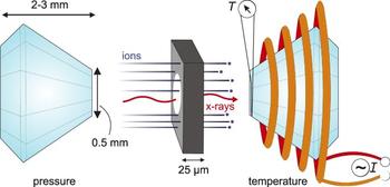
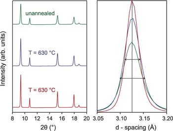
Small fractions of the irradiated sample pellets are further analyzed by removing material from inside the drilled holes with a sharp needle and transferring a small grain into a hydrothermal diamond anvil cell (HDAC). This apparatus serves as an advanced multipurpose sample chamber for synchrotron x-ray measurements. The sample chamber is prepared by slightly indenting a 0.25 mm thick rhenium foil between two diamond anvils. Rhenium, which is generally inert, is used to avoid chemical reactions with the sample at high temperature. A hole is drilled into the preindented area (diameter 50–200 µm) serving as a sample chamber for the irradiated material. The HDAC is closed by gently squeezing the two opposing diamond anvils against the rhenium foil (Fig. 9), which safely seals radioactive material within the sample chamber. No pressure is exerted onto the sample for ambient-pressure annealing measurements. An HDAC is a compact apparatus with a size of about 10 cm and is placed directly in the x-ray beam path at a synchrotron beamline dedicated to high-pressure experiments. The two diamonds of typical 2 mm thickness are semitransparent to high-energy x-rays; therefore, the structure of the sample is monitored as a function of increasing temperature by means of in situ micro synchrotron XRD analysis using the same beam configuration as for measurements at ambient conditions. Reference Palomares, Tracy, Zhang, Popov, Park, Trautmann, Ewing and Lang62 Molybdenum heating wires that are wrapped around each thermally conductive diamond are used to adjust the temperature at the sample site between the two diamonds. Chromel–Alumel thermocouples are placed close to the two anvil tips to monitor the temperature within the sample chamber (as shown in Fig. 9 for only one anvil). The use of a Basset-modified HDAC Reference Bassett63 allows exposure of samples to stable temperatures of up to 1000 °C. Samples can be exposed to even higher temperatures of up to 5000 °C by using dedicated heating lasers that are injected through both diamond windows of the pressure cell. Such experimental capabilities are available, for example, at beamline GSECARS 13 IDD. Reference Prakapenka, Kubo, Kuznetsov, Laskin, Shkurikhin, Dera, Rivers and Sutton64 The sample can be analyzed under such extreme conditions by in situ XRD to determine the high-temperature phase diagram or establish melting curves under ambient and high-pressure conditions. The small size of the sample in relation to the heated diamond anvils in a HDAC yields homogeneous temperatures throughout the entire sample chamber with negligible thermal gradients and temperature fluctuations. The high thermal conductivity of the diamonds and the use of cooling gas (flowing around the diamonds) enable precise temperature control with very short ramping times during both temperature increase and decrease. If the high-temperature synchrotron measurements are conducted in situ (i.e., at high temperature), the thermal expansion of the irradiated nuclear material is studied, while intermittent quenching and subsequent measurement at room temperature allow investigation of the isochronal annealing kinetics of irradiation-induced structural modifications. Details of these procedures are described for irradiated ThO2 and CeO2 elsewhere. Reference Palomares, Tracy, Zhang, Popov, Park, Trautmann, Ewing and Lang62 Figure 10 shows a qualitative trend for irradiated CeO2 (950 MeV Au ions of fluence 5 × 10¹³ ions/cm2) before and after isochronally annealing for 20 min at 350 and 630 °C. In contrast to the effect of defect-induced unit-cell expansion with increasing irradiation [Fig. 5(b)], increasing temperature leads to a slight shift of diffraction maxima to smaller d-spacing. This shift is too small to be observed in Fig. 10 but can be analyzed by Rietveld refinement. The analysis shows that annealing up to 630 °C leads to a reduction of the unit-cell parameter of 0.0013 Å (Δa/a = 0.025%). This thermally induced defect recovery is accompanied by a reduction in the heterogeneous microstrain as shown by the sharpening of diffraction maxima (Fig. 10). The intensity of diffraction maxima increases with increasing temperature as a result of defect annealing and recovery of the fluorite structure. The activation energy of the different thermally activated defect recovery processes is determined by Arrhenius-plots from systematic investigations of the peak width and position as a function of temperature. In agreement with the aforementioned results that illustrate the degree of unit-cell expansion in irradiated samples, activation energies deduced from swift heavy ion irradiated ThO2 and CeO2 are about one order of magnitude smaller than those obtained by Weber Reference Weber51 for alpha-particle irradiations of the similar fluorite materials. This indicates that the defect morphology produced by swift heavy ions in fluorite-structure oxides, and the associated defect annealing kinetics, is different as compared to that produced by alpha particles, which possess a significant nuclear energy loss component. Reference Weber51,Reference Palomares, Tracy, Zhang, Popov, Park, Trautmann, Ewing and Lang62 In summary, combining synchrotron XRD measurements with HDAC apparatuses is a very advantageous approach for the characterization of damage recovery in micrograms of irradiated nuclear materials at high temperatures. The remarkable thermal stability of the sample chamber together with the high resolution of synchrotron x-rays enable one to evaluate the annealing of defects involving very small unit cell parameter changes on the order of 0.01%.
Schematic illustration of synchrotron experiments for irradiated nuclear materials exposure to high temperature and/or high pressure. The very small sample (∼50 µm in diameter and ∼25 µm thick) is placed in a rhenium-gasket sample chamber and enclosed in a HDAC. The synchrotron x-rays completely penetrate both diamond anvils and the sample, and XRD patterns are collected as a function of increasing temperature (using resistance heating coils wrapped around the diamonds) and/or pressure (squeezing both diamonds against the gasket and sample).

Representative XRD patterns of irradiated CeO2 (950 MeV Au ions of fluence 5 × 1013 cm−2) before and after isochronal annealing for 20 min at different temperatures within a HDAC. Peak shifts to larger 2θ values (smaller d-spacing), peak sharpening, and an increase in the intensity of all peaks occur with increasing temperature (opposed to increasing ion fluence in Fig. 5). These observations are in agreement with a thermally induced defect recovery.

VI. HIGH-PRESSURE EXPERIMENTS
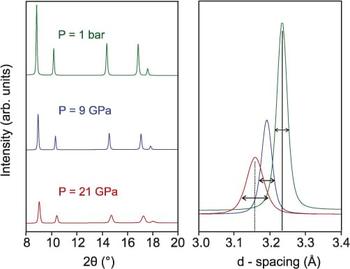
By filling the sample chamber with a pressure medium (e.g., methanol/ethanol) and distributing several small grains of ruby pressure calibrant throughout the chamber, high-pressure experiments can be conducted on preirradiated nuclear materials. The pressure is created by driving the diamonds toward each other and monitored by measuring laser-induced fluorescence of the small ruby grains. The wave length of the two ruby peaks is highly sensitive to pressure. Reference Mao, Xu and Bell65 Depending on the culet face of the diamond anvils, pressures of up to 400 GPa (4 Mbar) can be reached. Similar to the high-temperature experiments, synchrotron measurements are used to study the combined effects of irradiation and pressure on the stability of nuclear materials. Figure 11 shows that the increase of pressure up to 21 GPa leads to a further reduction in peak intensity in the XRD patterns of preirradiated ThO2 (950 MeV Au ions of fluence 5 × 10¹³ ions/cm2) from pressure-induced defects. The unit cell expansion due to ion-induced defects (Fig. 5) is reversed under pressure as indicated by the peak shift to smaller d-spacing. The width of the initially broadened peak is further increased due to the additional strain from the pressure and the formation of defects. By systematically measuring the d-spacing as a function of the increasing pressure of an irradiated and unirradiated sample, the effect of radiation damage on the bulk modulus of nuclear materials can be tested. Depending on the use of pressure medium and HDAC configuration, it is also possible to apply nonhydrostatic pressure or stress onto the irradiated samples.
Representative XRD patterns of irradiated ThO2 (950 MeV Au ions of fluence 5 × 1013 cm−2) before and after exposure to different pressures within a diamond-anvil cell (DAC). Peak shifts to larger 2θ values (smaller d-spacing) occur with increasing pressure as a result of lattice compression. Peak broadening and a decrease in the intensity of all peaks indicate pressure-induced defect formation.

Finally, ion irradiation and high pressure can be combined simultaneously to study the response of nuclear materials to coupled extreme conditions. This approach is based on a recently developed method using relativistic projectiles produced by the heavy ion synchrotron SIS at GSI. Reference Glasmacher, Lang, Keppler, Langenhorst, Neumann, Schardt, Trautmann and Wagner66 To reach the pressurized sample, the ions have to traverse the mm-thick diamond anvil of the high-pressure cell. This requires ion beams of relativistic energies on the order of 200 MeV/u. Within the highly pressurized material, the intense electronic excitations and ionizations produced by the ions trigger complex processes including subthreshold phase transformations. Reference Lang, Zhang, Zhang, Wang, Schuster, Trautmann, Neumann, Becker and Ewing43,Reference Glasmacher, Lang, Keppler, Langenhorst, Neumann, Schardt, Trautmann and Wagner66,Reference Schuster, Fujara, Merk, Neumann, Seidl and Trautmann67 Nanoscale manipulation by energetic projectiles provides a unique tool for in situ modifications of the thermodynamic pathways of pressurized materials. As an application, it has been demonstrated that high-pressure coupled with the deposition of large energy densities provides a new method for the recovery of unique, high-pressure structures that are otherwise inaccessible. Reference Lang, Zhang, Zhang, Wang, Schuster, Trautmann, Neumann, Becker and Ewing43
VII. CONCLUSIONS
The investigation of radiation effects in nuclear materials with synchrotron x-rays is in general limited by the lack of beamlines dedicated to radioactive materials and radiation safety constraints at large user facilities. However, SR is a characterization technique that is essential for obtaining valuable information on the nanoscale response of materials to irradiation. SR can be used to obtain unit-cell parameters of defective materials, establish phase fractions from irradiation-induced crystalline-to-crystalline phase transformations, investigate the amorphization process, or measure other modifications, such as changes in grain size or heterogeneous microstrain. By combining energetic ion irradiation and highly focused x-ray beams, structural and chemical modifications can be investigated in nuclear materials with very small sample volumes. This minimizes the level of radioactivity at the ion-beam and synchrotron user facility. The irradiated samples can be further analyzed by complementary characterization techniques, such as Raman spectroscopy, small angle x-ray scattering, and TEM. The use of externally or laser heated high-pressure apparatuses is a new means to expose irradiated materials to precisely controlled high-temperature and/or high-pressure conditions. The annealing kinetics of radiation damaged nuclear materials can be characterized in situ with synchrotron x-rays as a function of increasing temperature conditions, while phase transformation and bulk modulus modifications are investigated as a function of increasing pressure. Using relativistic ion energies (∼200 MeV/u), the mm-thick anvils of high-pressure cells can be fully penetrated, which allows for the in situ study of a material's response to multiple extreme conditions including ion irradiation, high pressure, and high temperature.
ACKNOWLEDGMENTS
This work was supported as part of the Materials Science of Actinides, an Energy Frontier Research Center funded by the U.S. Department of Energy, Office of Science, Office of Basic Energy Sciences under Award #DE-SC0001089. Portions of this work were performed at HPCAT (Sector 16), Advanced Photon Source (APS), Argonne National Laboratory. HPCAT operations are supported by DOE-NNSA under Award #DE-NA0001974 and DOE-BES under Award #DE-FG02-99ER45775, with partial instrumentation funding by NSF. HPCAT beamtime was granted by the Carnegie/DOE Alliance Center (CDAC). GeoSoilEnviroCARS is supported by the National Science Foundation - Earth Sciences (EAR-1128799) and Department of Energy - GeoSciences (DE-FG02-94ER14466). This research used resources of the Advanced Photon Source, a U.S. Department of Energy (DOE) Office of Science User Facility operated for the DOE Office of Science by Argonne National Laboratory under Contract No. DE-AC02-06CH11357.