1. Introduction
Impinging shock/boundary-layer interaction (SBLI) causes an adverse pressure gradient that leads to boundary layer separation with higher surface pressure and heat load, occurring across the internal and external surfaces of hypersonic vehicles (Dolling Reference Dolling2001). In the case of scramjet flowpaths, engine unstart might occur due to a large-scale boundary layer separation (Gai & Khraibut Reference Gai and Khraibut2019). On the vehicle airframe, extreme local pressure and heat loads require structural/thermal protection considerations. Given the complexity of the fluid phenomenon and the relative infancy of our understanding, numerous experimental investigations have been conducted using ‘canonical’ models to better understand these complex flow features.
Previous SBLI experiments in hypersonic impulse facilities examined the high-temperature aerothermodynamic effects of flow separation in various model configurations. Such configurations include compression ramp/double wedge (Mallinson, Gai & Mudford Reference Mallinson, Gai and Mudford1997; Bleilebens & Olivier Reference Bleilebens and Olivier2006; Swantek & Austin Reference Swantek and Austin2015; Knisely & Austin Reference Knisely and Austin2016; Wagner et al. Reference Wagner, Schramm, Hannemann, Whitside, Hickey and Kontis2018) and impinging shock (Sandham et al. Reference Sandham, Schülein, Wagner, Willems and Steelant2014; Sriram & Jagadeesh Reference Sriram and Jagadeesh2015; Sriram et al. Reference Sriram, Srinath, Devaraj and Jagadeesh2016). In the two-dimensional impinging shock configuration, Sandham et al. (Reference Sandham, Schülein, Wagner, Willems and Steelant2014) observed enhanced transition from impinging an oblique shock with a deflection angle of  $2^{\circ }$ and
 $4^{\circ }$ at Mach 6; however, the shock strength was not sufficient to fully separate the boundary layer. Researchers at the Indian Institute of Science (Sriram & Jagadeesh Reference Sriram and Jagadeesh2015; Sriram et al. Reference Sriram, Srinath, Devaraj and Jagadeesh2016) utilised a model with higher deflection angles of
 $27^{\circ }$ or
 ${31}^{\circ }$ to examine the laminar separation length
 $L_{sep}$, the streamwise distance from the start of the separation to the impingement point. An inviscid scaling law between
 $L_{sep}$ and the reattachment pressure ratio was developed using their data.
In addition, the wall temperature  $T_{w}$ has been observed to act as an important parameter in flow separation. During their high-dynamic-pressure trajectory (Billig Reference Billig1993), scramjets experience radiative wall cooling and internal heat transfer so
 $T_{w}$ equilibrates lower than the recovery temperature
 $T_{r}$; also, the wall-to-total temperature ratio
 $T_{w}/T_{s}$ will be much smaller than 1. Nonetheless,
 $T_{w}$ will be several times higher than the free-stream temperature
 $T_{\infty }$; therefore it changes the boundary layer properties and the extent of flow separation. Since the change in
 $T_{w}$ is negligible during the millisecond-order test duration of impulse facilities, model preheating has been employed to simulate realistic thermal conditions of hypersonic flight. Early efforts by Elfstrom (Reference Elfstrom1972) used preheating of a compression-ramp model in a gun tunnel that achieved
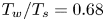 $T_{w}/T_{s}=0.68$ at Mach 9.22 to examine the effect of elevated
 $T_{w}$ on flow separation. Bleilebens & Olivier (Reference Bleilebens and Olivier2006) also preheated the surface of a compression-ramp model at a higher nozzle-supply enthalpy
 $H_{s}=5.0\ \textrm {MJ}\ \textrm {kg}^{-1}$ flow in a shock tunnel, and developed a modification of the scaling law of Katzer (Reference Katzer1989) to better account for
 $T_{w}$. Recent works by Wagner et al. (Reference Wagner, Schramm, Hannemann, Whitside, Hickey and Kontis2018) have also explored the effect of a heated wall in a large-scale compression-corner model. Experimental data on an impinging SBLI configuration with hot walls in high-speed flows are scarcer than compression-corner studies. Jaunet, Debieve & Dupont (Reference Jaunet, Debieve and Dupont2014) observed a growth of
 $L_{sep}$ with the heated wall that achieved wall-to-recovery temperature ratio
 $T_{w}/T_{r}=1.9$ at Mach 2.3 supersonic flow. No hypersonic experimental data are currently available exploring the heated-wall, impinging SBLI configuration. The most relevant work is the numerical work of Volpiani, Bernardini & Larsson (Reference Volpiani, Bernardini and Larsson2020) that simulated a heated (isothermal) wall boundary condition for the unheated Mach 5 impinging SBLI experiments (Schülein Reference Schülein2006).
The work reported herein presents experimental results concerning shock impingement on a heated flat plate at high-Mach-number flight test conditions, which has not been explored previously in the literature. In recent work (Chang et al. Reference Chang, Chan, Hopkins, McIntyre and Veeraragavan2020), the authors found that the flat plate boundary layer thickened with higher  $T_w$ from the hypersonic flow testing of a heated flat plate. In the present study, the authors installed a shock generator to generate a strong oblique shock to separate the flat plate boundary layer. With the preliminary numerical simulations (Chang et al. Reference Chang, Chan, McIntyre and Veeraragavan2019) predicting the growth of flow separation with wall heating, the authors aim to experimentally characterise and quantify the behaviour of flow separation for an impinging-shock heated-flat-plate model subjected to hypersonic flow in the University of Queensland's T4 shock tunnel.
2. Experimental details
2.1. Test facility and flow conditions
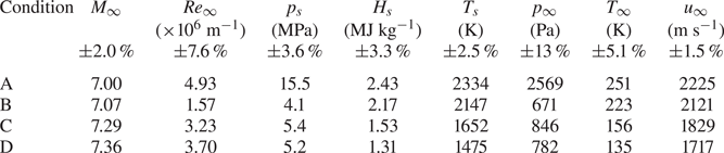
All experiments were conducted in the T4 Stalker Tube (reflected shock tunnel) at the University of Queensland, Australia. T4 utilises piston compression of the driver gas to generate high nozzle-supply pressures and temperatures for a wide range of hypersonic flight conditions (Stalker et al. Reference Stalker, Paull, Mee, Morgan and Jacobs2005). Table 1 shows the mean nozzle-supply and free-stream (nozzle-exit) properties of a Mach 7 axisymmetric nozzle (Chan et al. Reference Chan, Jacobs, Smart, Grieve, Craddock and Doherty2018). Conditions A and B examined Mach 7 flight enthalpy at pressures equivalent to flight at 25 and 33.5 km, respectively. Conditions C and D produced ‘off-design’ flow conditions with Mach 5.5 ( $1.53\ \textrm {MJ}\ \textrm {kg}^{-1}$) and 5.0 (
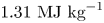 $1.31\ \textrm {MJ}\ \textrm {kg}^{-1}$) flight enthalpies. ESTCj (Jacobs et al. Reference Jacobs, Gollan, Potter, Zander, Gildfind, Blyton, Chan and Doherty2014) was used to calculate the properties, and the experimental uncertainties were computed by the process outlined in Mee (Reference Mee1993). The real-gas effects in the nozzle expansion were negligible at these low-enthalpy conditions, because the mass spectrometer studies of the nozzle supply and free stream in the T4 Stalker Tube (Boyce, Takahashi & Stalker Reference Boyce, Takahashi and Stalker2005a,Reference Boyce, Takahashi and Stalkerb) showed good agreement with ESTCj calculations assuming chemical equilibrium up to
 ${\approx }3\ \textrm {MJ}\ \textrm {kg}^{-1}$.
Mean facility nozzle-supply (subscript  $s$) and free-stream (subscript
 $\infty$) properties of the present experiments.

2.2. Experimental model and flow diagnostics
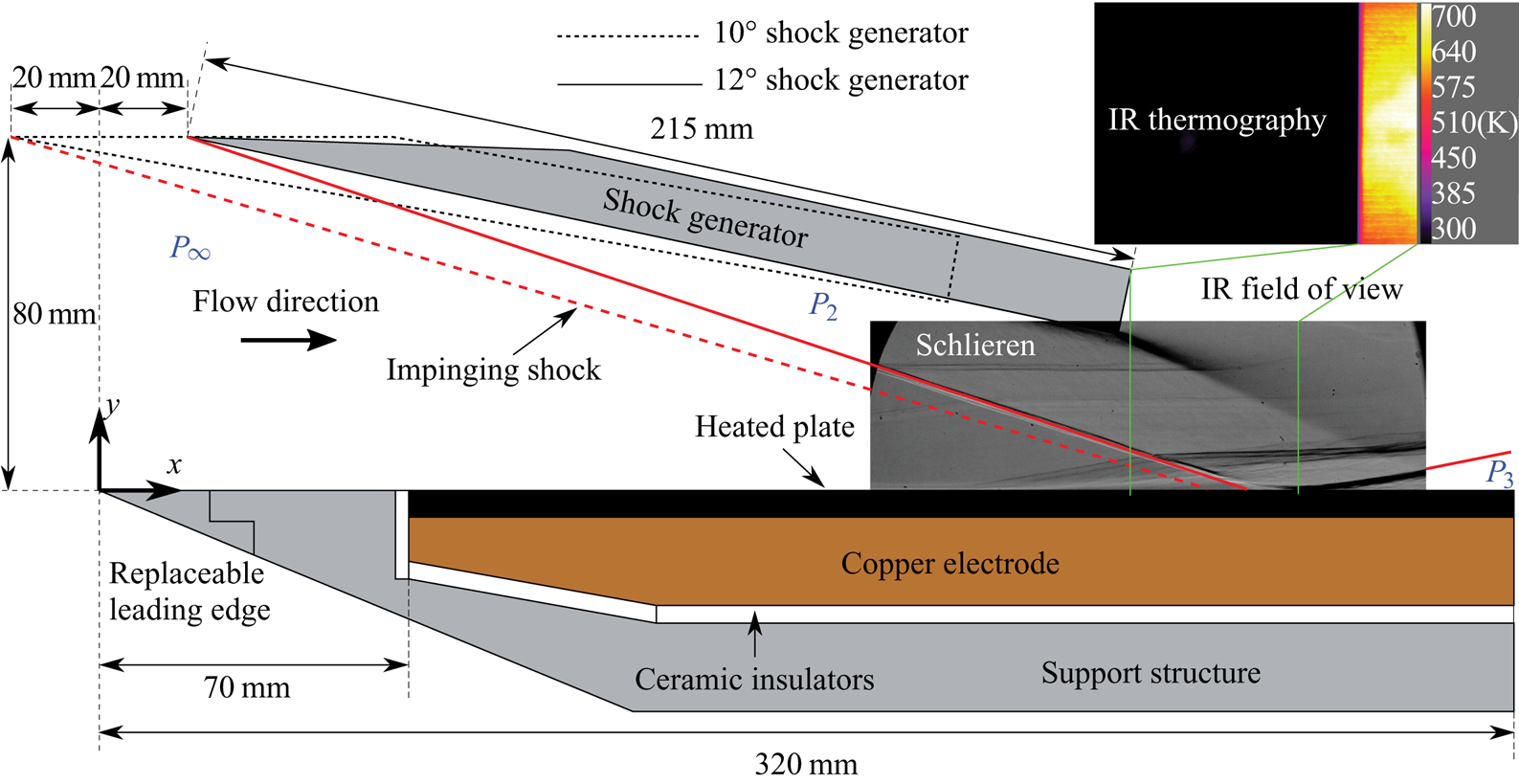
Figure 1 shows a schematic of the heated plate model. The flat plate consisted of a 70 mm front section and a 250 mm heated section. The front section had a sharp ( $r<0.1\ \textrm {mm}$), replaceable leading edge. Direct-circuit current applied through copper electrodes resistively heated an isotropic graphite plate 250 mm long and 200 mm wide to temperatures
 $T_w$ that were over 800 K in a minute. The graphite plate was electrically isolated from the model structure using alumina (
 $\textrm {Al}_{2}\textrm {O}_{3}$) ceramic insulators. Further information regarding the design and testing of the heated flat plate is provided in Chang et al. (Reference Chang, Chan, Hopkins, McIntyre and Veeraragavan2020). In addition to the heated plate, an unheated instrumented plate was also utilised to obtain the quantitative surface data. The instrumented plate had the same surface finish as the heated plate, but a longer length to record the properties downstream of the interaction. The 43 Kulite
 $^{(R)}$ XTEL-190 (M) pressure transducers were distributed from
 $x=121$ mm to
 $x=394$ mm in two rows spaced 13 mm apart (centreline and 13 mm spanwise offset). Next to the centreline, 35 thin-film heat transfer gauges were distributed from
 $x=102$ mm to
 $x=561$ mm with a 13.5 mm spacing. All channels for the sensors were sampled at 1 MHz. Although not shown for brevity, the steady measurement was confirmed in all surface instrumentation within the total available test duration of the T4 Stalker Tube.
Schematic of the heated model and fields of view for optical diagnostics.

A shock generator plate 215 mm long and 172 mm wide was mounted above the heated flat plate. Two deflection angles of  $10^{\circ }$ (dashed line) and
 $12^{\circ }$ (solid line) relative to the free stream generated inviscid shock strengths of
 $p_2/p_{\infty } = 4.38$ and
 $p_2/p_{\infty } = 5.53$, respectively. For both deflection angles, the leading edge of the shock generator was positioned 80 mm above the flat plate to avoid interaction with the weak viscous-interaction shock from boundary-layer growth, starting from the flat plate leading edge. In the streamwise direction, the leading edge was positioned 20 mm upstream from the flat plate leading edge for the
 $10^{\circ }$ generator and 20 mm downstream for the
 $12^{\circ }$ generator. This ensured the oblique shock was well displaced from the expansion waves emanating from the trailing edge of the shock generator at the impingement point. From theoretical estimation, the oblique shocks from the
 $10^{\circ }$ and
 $12^{\circ }$ deflection of the
 $M_{\infty }=7$ free stream were expected to impinge at 252 and 260 mm downstream, respectively, from the flat plate leading edge.
The boundary layer height ( $\delta$) at the shock impingement location (
 $x\approx 260\ \textrm {mm}$) for Condition A was found to be
 ${\approx }2.1\ \textrm {mm}$ and
 ${\approx }2.9\ \textrm {mm}$ for the unheated (
 $T_w = 298$ K) and heated (
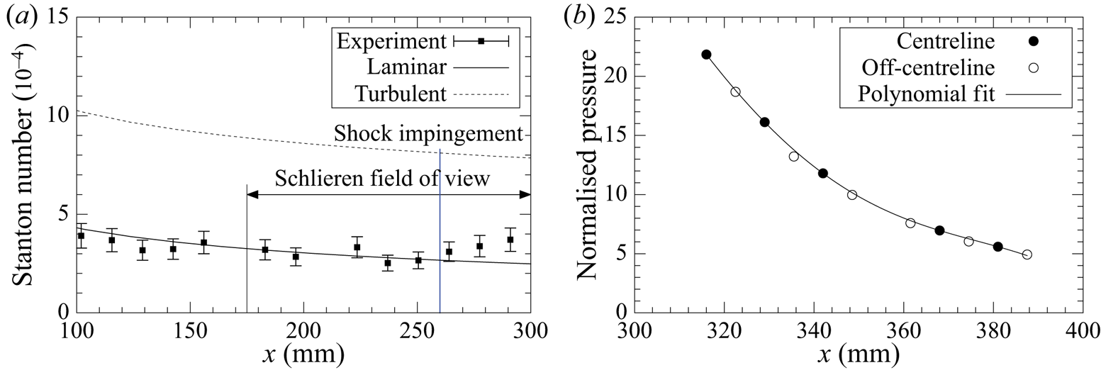
 $T_w\approx 720$ K) wall cases, respectively, based on our previous results (Chang et al. Reference Chang, Chan, Hopkins, McIntyre and Veeraragavan2020). When heated, the boundary layer thickened and formed ‘rope-like’ structures at a more upstream location. This suggests that the heated boundary layer may have exhibited transitional behaviour. Figure 2(a) shows the measured Stanton number distribution of the undisturbed boundary layer. Here, heat transfer data are presented via the free-stream Stanton number. Comparison with the theoretical calculation of Cebeci & Bradshaw (Reference Cebeci and Bradshaw2012) confirms that the unheated boundary layer of Condition A is laminar at the shock impingement. Therefore, all other results in the low-Reynolds-number conditions may be considered laminar as well. Next, in order to minimise three-dimensional effects the model was designed to be as large as possible within the Mach 7 nozzle core-flow to keep the flow spillage as far away from the measurement locations as possible. The two-dimensionality is verified by a good agreement between the normalised pressures (by the first sensor at
 $x=121$ mm) at the two spanwise locations downstream of the interaction, as shown in figure 2(b).
Instrumented plate results, Condition A. (a) Stanton number of the undisturbed boundary layer. (b) Static pressure in two spanwise locations.

For optical diagnostics, schlieren and an infrared (IR) thermography system were employed to characterise the flow field and plate temperature, as described in Chang et al. (Reference Chang, Chan, Hopkins, McIntyre and Veeraragavan2020). The schlieren field of view is shown in figure 1. In the streamwise direction, the field of view covered from  $x=175$ mm to
 $x=300$ mm. In the vertical direction, the field of view included the trailing edge of the shock generator, which is 40 mm above the plate surface. The images were captured at 15 000 frames per second with an exposure time of
 $1\ \mathrm {\mu }\textrm {s}$. The surface temperature distribution of the plate was captured by a FLIR AC655 camera mounted vertically above the T4 test section. The IR image shown in figure 1 included a portion of a heated plate with a field of view of
 $30\ \textrm {mm}\times 95\ \textrm {mm}$. The calibration technique from the previous work utilising thermocouples was used to estimate the wall temperature of the heated plate in an actual shot (experimental run).
3. Results and discussion
3.1. Flow establishment
The millisecond-order test duration ( $t$) in the T4 shock tunnel requires verification to ensure that the flow separation is not evolving temporally during the steady test-time. The time required to establish a steady flow separation,
 $t_{sep}$, is examined as follows. For the separation of compression-corner flows in a shock tunnel, Holden (Reference Holden1971) employed the acoustic disturbance to traverse the interaction length,
 $L_{sep}$, at the mean speed of sound in the boundary layer,
 ${a_\delta }$, to develop
 $t_{sep} = L_{sep}/{a_\delta }$. With regard to the present model with
 $L_{sep} = 90\ \textrm {mm}$ (maximum field of view upstream of the shock impingement), using this correlation gives an estimate of
 $t_{sep} \approx 0.18\ \textrm {ms}$. Sriram et al. (Reference Sriram, Srinath, Devaraj and Jagadeesh2016) discovered that the
 $t_{sep}$ values of an impinging shock geometry at
 $M_{\infty }=5.88$ and
 $M_{\infty }=8.54$ were measured to be shorter than the estimates from the correlation of Holden (Reference Holden1971). Further experimental studies using surface heat transfer measurement and flow visualisation (Swantek & Austin Reference Swantek and Austin2015; Knisely & Austin Reference Knisely and Austin2016) observed
 $t_{sep}$ about two to eight flow lengths for compression-corner geometries. For the streamwise length of 320 mm in the present model, two to eight flow lengths results in
 $t_{sep}$ estimates from approximately
 $0.29$ to 1.15 ms. This is a conservate estimate as
 $L_{sep}$ will be much smaller than 320 mm.
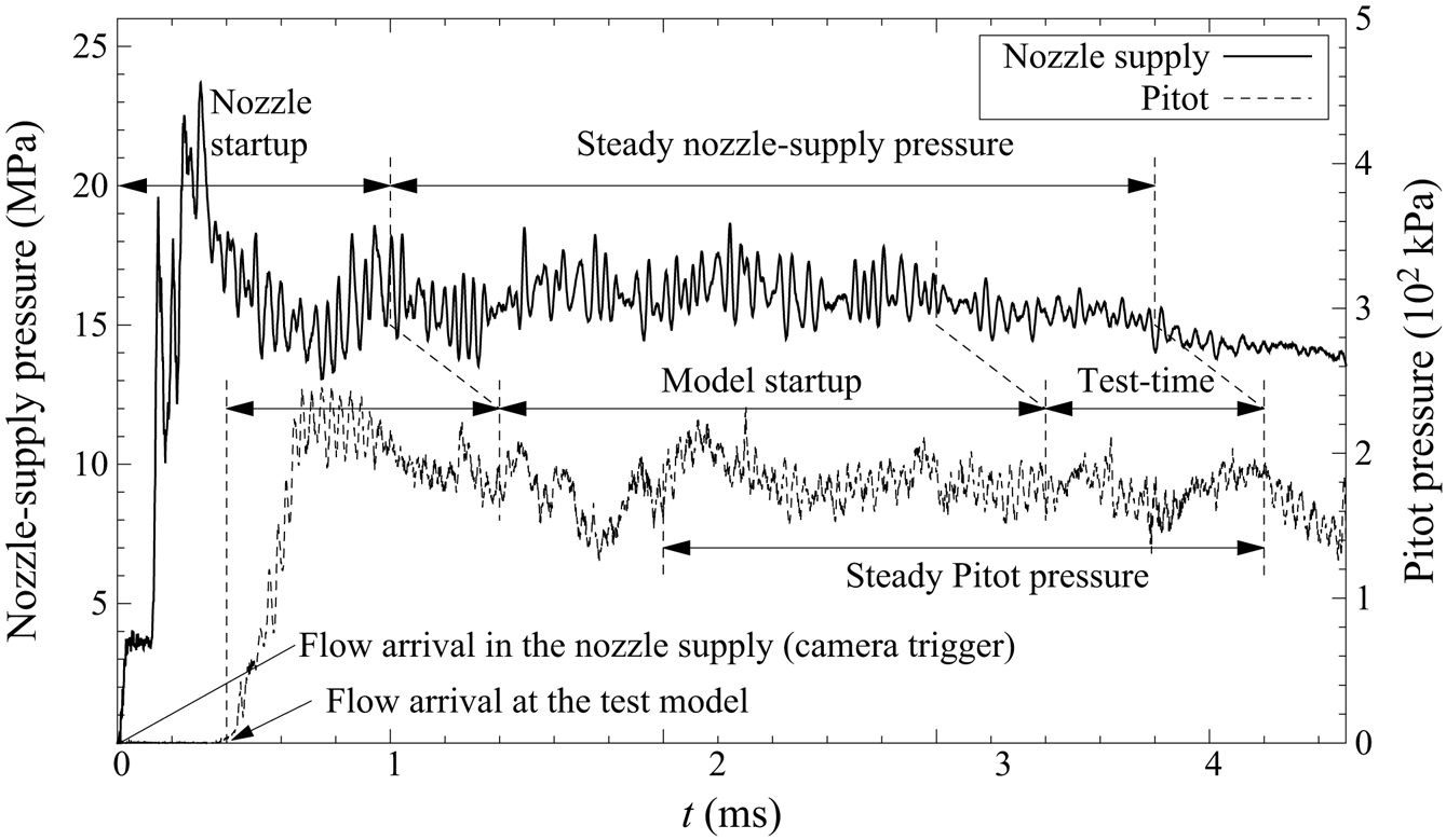
Measured piezoelectric pressure signals from a representative shot are plotted in figure 3. The  $t$ label in the axis represents the time since the data acquisition system was triggered by the reading of the pressure sensor located in the nozzle supply. The nozzle-supply pressure remains fairly steady until
 $t\approx 3.8\ \textrm {ms}$, at which time it starts to drop. The drop in pressure indicates the end of the available steady test-time. Note that driver gas contamination is expected to occur well after the end of the test duration, as approximated using the correlation by Boyce et al. (Reference Boyce, Takahashi and Stalker2005a). The facility nozzle requires
 $t\approx 1\ \textrm {ms}$ (Chan et al. Reference Chan, Jacobs, Smart, Grieve, Craddock and Doherty2018) to establish, and the flow requires about 0.4 ms to travel from the nozzle supply to the Pitot probe aligned with the model leading edge. Due to the delay in this flow traversal time, the steady Pitot pressure is only reached at
 $t\approx 2\ \textrm {ms}$ and remains steady for
 ${\approx }2.2\ \textrm {ms}$. Therefore, in the present study we have sufficient test-time that is greater than the minimum
 $t_{sep}$.
Test flow examination from measured piezoelectric pressure signals.

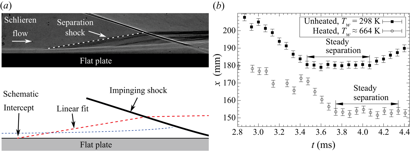
In order to accurately characterise the steady separation, the onset of separation was approximated as the location where the separation shock intersects the flat plate, similarly to the method of Sriram et al. (Reference Sriram, Srinath, Devaraj and Jagadeesh2016). For the present study, a linear line fit along the separation shock was extrapolated to the flat plate surface, as illustrated in figure 4(a). The shock location throughout the steady inflow on the model is plotted in figure 4(b). When  $t = 3$ ms, the separation shock gradually moves upstream from 200 mm to 180 mm until reaching a steady location at around
 $t= 3.5\ \textrm {ms}$ for the unheated case (filled square symbols in figure 4b). The shock position remains relatively steady for about 0.6 ms, labeled as ‘test-time’ in figure 3. Similarly to the observations of Sriram et al. (Reference Sriram, Srinath, Devaraj and Jagadeesh2016), the separation shock oscillates slightly during the steady inflow, with an amplitude of
 $\pm$2 mm for the present data. The shock position itself oscillates due to the inherent unsteadiness involved in SBLI and free-stream disturbances in shock tunnel flows. For the heated case (filled circle symbols in figure 4b), the steady test-time occurs at
 $t\approx 3.8\ \textrm {ms}$, due to the larger size of the separation bubble. After the steady test-time, the decrease in nozzle-supply pressure causes the separation shock to become unstable.
Linear fit to determine the separation shock location during the test-time. (a) Linear fit. (b) Separation shock location.

3.2. Flow separation visualisation
Steady SBLI flow-field images of all experimental results are displayed in figures 5 to 7. All images were truncated vertically to zoom in on the boundary layer. The  $x$ and
 $y$ labels are the streamwise distance from the flat plate leading edge and the height above the plate surface, respectively. Wall-to-recovery temperature ratio (
 $T_{w}/T_{r}$) and shot-specific
 $Re_{\infty }$ are also included in the caption. The results presented herein are twofold: first with the unheated wall for all flow conditions, and next with the heated wall for the two different shock generator angle configurations.
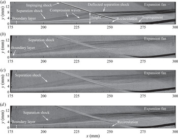
Unheated model with impinging SBLI flow field: 12 $^{\circ }$ shock generator. (a) Condition A,
 $T_{w}/T_{\infty } = 1.24$,
 $T_{w}/T_{r} = 0.156$,
 $Re_{\infty } = 5.25\times 10^{6}\ \textrm {m}^{-1}$,
 $t = 3.86\ \textrm {ms}$. (b) Condition B,
 $T_{w}/T_{\infty } = 1.35$,
 $T_{w}/T_{r} = 0.163$,
 $Re_{\infty } = 1.54\times 10^{6}\ \textrm {m}^{-1}$,
 $t = 3.85\ \textrm {ms}$. (c) Condition C,
 $T_{w}/T_{\infty } = 1.92$,
 $T_{w}/T_{r} = 0.222$,
 $Re_{\infty } = 3.15\times 10^{6}\ \textrm {m}^{-1}$,
 $t = 3.87\ \textrm {ms}$. (d) Condition D,
 $T_{w}/T_{\infty } = 2.22$,
 $T_{w}/T_{r} = 0.250$,
 $Re_{\infty } = 3.70\times 10^{6}\ \textrm {m}^{-1}$,
 $t = 3.79\ \textrm {ms}$.

Figure 5 shows the steady flow separation of unheated boundary layers for the  ${12}^{\circ }$ shock generator. Figure 5(a) depicts the separation shock, compression waves, flow recirculation and expansion fan in the flow field; these are the typical features of a large-scale laminar separation bubble that have been observed in previous studies (Sriram et al. Reference Sriram, Srinath, Devaraj and Jagadeesh2016; Gai & Khraibut Reference Gai and Khraibut2019). For the results shown in figure 5, the extent of separation depends highly on a combination of
 $Re_{\infty }$ and
 $T_{w}/T_{\infty }$. Conditions A and B have a similar
 $T_{w}/T_{\infty }$; however, the lower
 $Re_{\infty } = 1.54\times 10^{6}\ \textrm {m}^{-1}$ of Condition B induces a larger separation, as seen in figure 5(b). Also, the
 $T_{w}/T_{\infty }$ values are obtained by changing
 $T_{\infty }$, not by increasing
 $T_{w}$. This means the ‘off-design’ Condition D (figure 5d) has the lowest
 $T_{\infty }$ and
 $U_{\infty }$ and forms the thinnest boundary layer. Combined with a higher
 $Re_{\infty }$, Condition D produces the smallest separation, as expected.
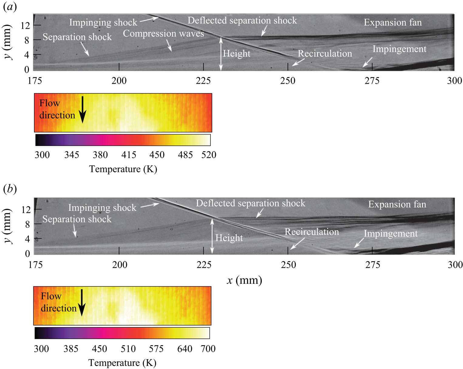
Figure 6 demonstrates the influence of the elevated  $T_w$ on flow separation for Condition A. Comparison of figures 5(a) and 6(a,b) reveals that
 $L_{sep}$ grows first from 80 to 90 mm, and then to 107 mm, as the averaged
 $T_{w}$ increases from 298 to 493 K, and then to 664 K, respectively. With an upstream separation, the area enclosed by the separation shock and an impinging shock (the separation bubble) grows as well. In the recent flat plate testing of Chang et al. (Reference Chang, Chan, Hopkins, McIntyre and Veeraragavan2020), a thicker boundary layer formed when the wall was heated. A heated, thicker boundary layer has a lower density. Therefore, the adverse pressure from the impinging shock dissipates into a lower density, resulting in the separation shock forming at a more upstream location. Figure 7 shows that the wall heating increases
 $L_{sep}$ with the
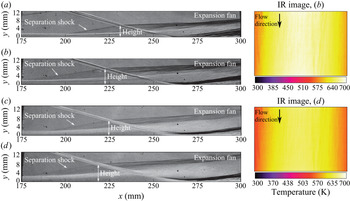
 $10^{\circ }$ shock generator for Conditions A and C. The more upstream position of the shock generator allows a wider IR image field of view. Owing to the lower shock strength, the
 $10^{\circ }$ shock generator configuration leads to smaller separation bubbles compared to the
 $12^{\circ }$ results. Condition C has a lower
 $Re_{\infty }$; therefore, for the unheated case (figure 7c), it produces a larger separation than Condition A (figure 7a). A high
 $T_{w}/T_{\infty }\approx 4.04$ could also be achieved when heated (figure 7d), allowing us to investigate a wider range of conditions.
Heated model with impinging SBLI flow field: 12 $^{\circ }$ shock generator. (a) Condition A,
 $T_{w}\approx 493$ K,
 $T_{w}/T_{\infty }\approx 1.98$,
 $T_{w}/T_{r}\approx 0.246$,
 $Re_{\infty } = 4.80\times 10^{6}\ \textrm {m}^{-1}$,
 $t = 3.58\ \textrm {ms}$. (b) Condition A,
 $T_{w}\approx 664$ K,
 $T_{w}/T_{\infty }\approx 2.77$,
 $T_{w}/T_{r}\approx 0.343$,
 $Re_{\infty } = 5.30\times 10^{6}\ \textrm {m}^{-1}$,
 $t = 3.86$ ms.

Heated model with impinging SBLI flow field:  ${10}^{\circ }$ shock generator. (a) Condition A,
 $T_{w}=298$ K,
 $T_{w}/T_{\infty }=1.25$,
 $T_{w}/T_{r}=0.154$. (b) Condition A,
 $T_{w}\approx 675$ K,
 $T_{w}/T_{\infty } \approx 2.76$,
 $T_{w}/T_{r}\approx 0.342$. (c) Condition C,
 $T_{w}=298$ K,
 $T_{w}/T_{\infty }=1.89$,
 $T_{w}/T_{r}=0.219$. (d) Condition C,
 $T_{w}\approx 639$ K,
 $T_{w}/T_{\infty }\approx 4.04$,
 $T_{w}/T_{r}\approx 0.466$.

For all conditions and configurations, the present experiment showcased that the separation bubbles for an impinging-shock flat plate in hypersonic flows grew with higher wall temperatures. The separation bubbles grew in both the streamwise direction and vertical height, which is consistent with the upstream shift in separation shock/pressure rise seen in other hot compression-ramp experiments (Elfstrom Reference Elfstrom1972; Bleilebens & Olivier Reference Bleilebens and Olivier2006). The growth of separation observed in these flight-representative test flows suggests that increasing  $T_w$ will create larger separated regions when the shock impinges on any surface of the hypersonic vehicle in flight. These separations will block the scramjet internal flowpath and increase the local drag when the vehicle is operated for a longer duration, leading to a significant decrease in performance.
3.3. Separation length scaling for hypersonic boundary layers
There are few separation length correlations in the literature which incorporate the effect of  $T_{w}$ in SBLI. Katzer (Reference Katzer1989) developed a correlation of the
 $L_{sep}$ and pressure ratio across the shock from his numerical study of supersonic shock impingement. In the experimental investigation of the hypersonic heated compression ramp (Bleilebens & Olivier Reference Bleilebens and Olivier2006), the scaled separation length (
 $K$) from the supersonic study (4.4) was modified as in (3.1) below to better account for the effect of elevated
 $T_{w}$:
 \begin{equation} \frac{L_{sep}}{{\delta_{i}}^{*}} = K {\frac{\sqrt{\dfrac{Re_{i}}{C}}}{M_{\infty}^3}}\left(\frac{p_r-p_{inc}}{p_{\infty}}\right),\quad K = 4.4\ or\ 4.4-0.2\left(\frac{T_{w}}{T_{\infty}}\right). \end{equation}
Here,  ${\delta _{i}}^{*}$ is the displacement thickness of the boundary layer.
 $C$ is the Chapman–Rubesin constant, defined by the product of wall-to-free-stream viscosity ratio and free-stream-to-wall temperature ratio
 $(\mu _{w}/\mu _{\infty })(T_{\infty }/T_{w})$. The subscripts
 $inc$,
 $i$ and
 $r$ refer to the conditions at the start of the separation location, impingement (hinge line for compression ramp) location and reattachment, respectively. The ratio
 $p_{inc}/p_{\infty }$ is determined by the approximation in Katzer (Reference Katzer1989). Note that Bleilebens & Olivier (Reference Bleilebens and Olivier2006) used the values at
 $inc$ for
 $i$, to better account for the free-interaction theory applying to their compression-ramp model. For the present configuration, the subscript
 $i$ denotes the properties at the impingement; theoretical calculations determined the locations with shot-specific flow conditions. Then
 $L_{sep}$ values measured from the shots, along with the isentropic flow relations to calculate
 $p_s$ and theoretical boundary layer equations of Cebeci & Bradshaw (Reference Cebeci and Bradshaw2012), are used to obtain
 $K$.
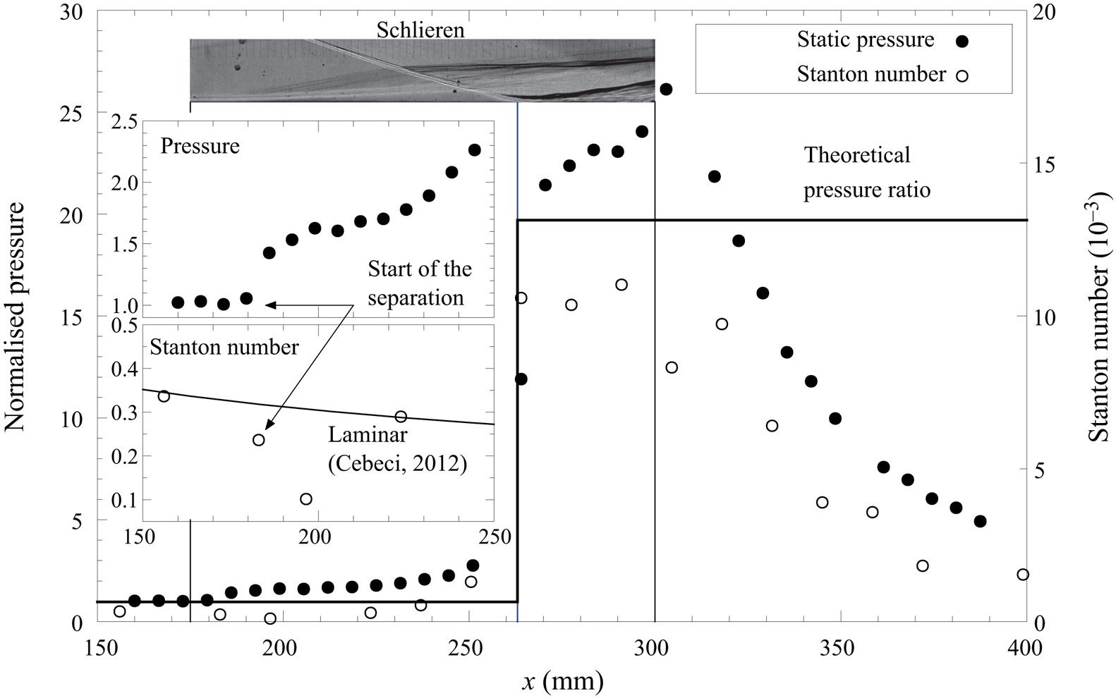
The mean surface properties of the instrumented plate are plotted in figure 8 to verify the use of theoretical calculations. The inset figure depicts the start of the separation at  $x=179.5$ mm, which is consistent with the linear fit from the schlieren image. Downstream of the onset of separation, the normalised pressure increases from 1.43 to 1.62 and then to 2.26, for
 $x=186$ mm to
 $x=199.5$ mm and
 $x=244.5$ mm, respectively. The averaged value over this range is 1.76. This closely matches the supersonic approximation of Katzer (Reference Katzer1989) for the same flow condition (
 $p_{inc}/p_{w}=1.79$). Even with the flow separation, the static pressure traces were fairly steady with time in these locations. The normalised pressure just behind the reflected shock (reattachment pressure) at
 $x=270.5$ mm is 21.4, which is 8.8 % higher than the theoretical pressure ratio across the shock (
 $p_3/p_{w}$). This disagreement could be attributed to experimental uncertainty and to shock-induced transition producing slightly higher pressures in the reattachment (Bleilebens & Olivier Reference Bleilebens and Olivier2006; Currao et al. Reference Currao, Choudhury, Gai, Neely and Buttsworth2020). Hence, the theoretical ratio could be employed for the present study. The Stanton number distribution shows that the upstream boundary layer is laminar. At
 $x=183$ mm and
 $x=196.5$ mm the Stanton number values decrease due to the thickening of the boundary layer. The shock impingement incites the turbulent transition. Maximum heat transfer is experienced until the expansion fan from the trailing edge of the shock generator reaches the plate at
 $x\approx 318$ mm.
Mean surface properties:  ${12}^{\circ }$ shock generator, Condition A.

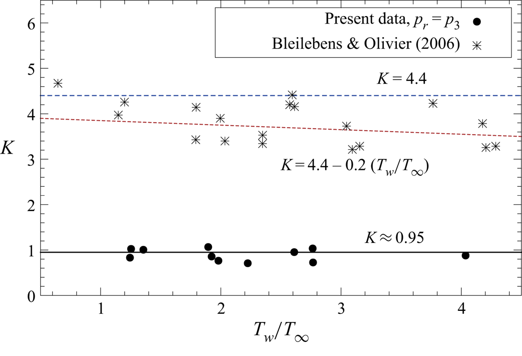
Figure 9 compares  $K$ versus
 $T_{w}/T_{\infty }$ of the present work against prior separation length correlations. The present data show good agreement with a constant
 $K\approx 0.95$. The effect of
 $T_w$ is mainly determined by
 $C$ in (3.1). For the present study, the
 $C$ values range from 0.75 to 0.95. The square root of the
 $C$ values is from 0.87 to 0.97, which is close to 1. Therefore,
 $K$ that is proportional to
 $\sqrt {C}$ shows a weak
 $T_w$ influence. The flow regimes are also different, with the supersonic scaling of Katzer (Reference Katzer1989) based on
 $M_{\infty }$ from
 $1.4$ to 3.4,
 $p_r/p_{\infty }$ from
 $1.2$ to 1.8 and
 $Re_{i}$ from
 $1\times 10^5$ to
 $6\times 10^5$. Hypersonic scaling (Bleilebens & Olivier Reference Bleilebens and Olivier2006) from the compression-corner study was based on
 $M_{\infty }$ from
 $7.1$ to 8.1,
 $p_r/p_{\infty }$ from
 $7.03$ to 11.5 (calculated from their experimentally measured coefficient of pressure
 $c_p\approx 0.2$ to
 $c_p\approx 0.25$) and
 $Re_{i}$ from approximately
 $3.3\times 10^5$ to
 $3.8\times 10^5$. The
 $p_r$ of the hypersonic compression ramp is effectively
 $p_2$, which is the pressure behind the ramp shock, whereas the
 $p_r$ of the shock impingement correlation is effectively
 $p_3$, because the reattachment occurs after an additional compression from the reflected shock. Hence, a higher
 $p_3/p_{\infty }$ value of
 $14$ to 22.1 and
 $Re_{i}$ of
 $4.1\times 10^5$ to
 $13\times 10^5$ for the present data, divided by
 $L_{sep}/{\delta _{i}}^{*}$, lead to a smaller
 $K$. The findings demonstrate that the flow separation length in hypersonic impinging SBLI with heated walls is influenced by the higher shock strength (measured by the pressure ratio), and cannot be easily deduced from previous supersonic impinging SBLI or hypersonic compression-ramp correlations.
Separation length scaling of the present data with  $T_{w}/T_{\infty }$.

4. Conclusions
This work showcased the effect of elevated wall temperatures in hypersonic impinging SBLI in Mach 7 flight-representative flows of the T4 shock tunnel. The test model was reliably heated and produced a large-scale, steady separation bubble during the facility test-time. By inspecting flow structures captured in schlieren images and using the transition criteria of T4, the unheated SBLI data in this work were all obtained with laminar flow. The  $12^{\circ }$ shock generator SBLI flow field for various flow conditions indicated a significant influence of Reynolds number on flow separation. For a fixed free-stream temperature and Reynolds number, a clear increase in separation length with increasing wall temperature was observed. Experiments with a
 $10^{\circ }$ shock generator also showed a decrease in the extent of separation compared to the
 $12^{\circ }$ cases, yet the higher wall temperature enlarged the separation. Existing correlations for laminar separation length as a function of wall temperature were also applied to the present data. A high discrepancy was observed between the current work and correlations from both the separation scaling of supersonic impinging shocks and its modification for the hypersonic compression ramp, mainly because of the higher shock strength in the present experiments, highlighting the need for additional data sets spanning more conditions in order to improve existing correlations. The increase of flow separation with elevated wall temperature is an important result for the future design and testing of scramjet flowpaths and hypersonic vehicles where this phenomenon must be considered.
Acknowledgements
The work was sponsored by the UQ–National University of Singapore Research Collaboration and the Air Force Office of Scientific Research under award number FA9550-18-1-0265, with Dr I. Leyva as the project manager. The computational resources were provided by the NCI Facility under the National Computational Merit Allocation Scheme, supported by the Australian Government. The authors acknowledge K. Hitchcock for technical support and T4 operators R. Whitside, A. Ward, I. Convery-Brien, R. Ananthapadmanaban and K. Hopkins for operating the T4 Stalker Tube facility. Special thanks to K. Hopkins for operating the power supply and helping with the IR calibration. E.W.K.C. acknowledges support through the University of Queensland Research Training Scholarship.
Declaration of interests
The authors report no conflict of interest.