1. Introduction
1.1 Background
Measures for automatic collision avoidance (CA) and obstacle avoidance (OA) of maritime autonomous surface ships (MASS) are highly complex and uncertain. When considering the motion of the ship, the International Regulations for Preventing Collisions at Sea (COLREGS) and restricted water areas, the automatic CA, OA, and path planning in complex waters are the focus and challenge of recent research works (Lyu and Yin, Reference Lyu and Yin2019b; Huang et al., Reference Huang, Chen, Chen, Negenborn and van Gelder2020).
The Electronic Chart Display Information System (ECDIS) is an important aid for navigation that must be installed in an up-to-date bridge system. It can present numerous accurate environmental data sets for MASS path planning systems, such as depth of water, obstacles, land areas, and limit of fairways. Therefore, the ideal environment model for a MASS automatic CA system should adapt to the data structure of the electronic navigational chart (ENC) as much as possible (Lyu and Yin, Reference Lyu and Yin2019a).
The spatial vector data in accordance with the S-57 and S-101 standards in ECDIS are represented by points, lines (curves), and faces (surfaces). The shapes of objects provided by ECDIS are usually overly complicated and have different characteristic attributes. When vessels navigate in restricted waters automatically, it is necessary to consider fully the various ENC data and their attributes, establish a navigation environment model, and perform automatic CA and path planning. In this study, establishing the navigational environment model based on the points, lines, and faces of ENC data is a research priority.
1.2 Literature review
1.2.1 Path planning method
Many algorithms have been used and adapted for collision-free path planning, and the techniques and key points of CA have been summarised in literature reviews (Tam et al., Reference Tam, Bucknall and Greig2009; Huang et al., Reference Huang, Chen, Chen, Negenborn and van Gelder2020; Panda et al., Reference Panda, Das, Subudhi and Pati2020; Vagale et al., Reference Vagale, Bye, Oucheikh, Osen and Fossen2021a, Reference Vagale, Bye, Oucheikh, Osen and Fossen2021b; Zhang et al., Reference Zhang, Wang, Jiang, An and Yang2021; Öztürk et al., Reference Öztürk, Akdağ and Ayabakan2022). Vagale et al. (Reference Vagale, Bye, Oucheikh, Osen and Fossen2021a) adopted a general categorisation of path planning algorithms based on Souissi et al. (Reference Souissi, Benatitallah, Duvivier, Artiba, Belanger and Feyzeau2013), and suggested that such algorithms can be classified as classical approach, advanced approach, and hybrid approach.
The classical approach is a two-step process consisting of (1) environment modelling to prepare for the search and (2) performing the search for the optimal path in this environment. This type of algorithm is used for global path planning where there is no need for local CA. The advanced approach does not require environmental modelling beforehand and can be used to deal with dynamic obstacles, local CA, and path re-planning in real time. The most often used machine learning algorithms (Cheng and Zhang, Reference Cheng and Zhang2018), potential field methods, velocity obstacles (Kuwata et al., Reference Kuwata, Wolf, Zarzhitsky and Huntsberger2014; Chen et al., Reference Chen, Huang, Mou and van Gelder2018; Shaobo et al., Reference Shaobo, Yingjun and Lianbo2020; Yuan et al., Reference Yuan, Zhang, Zhang, Zhang and Guedes Soares2021), dynamics widows (Eriksen et al., Reference Eriksen, Wilthil, Flåten, Brekke and Breivik2018; Wang et al., Reference Wang, Gao, Zheng, Zhao and Yin2018), and the vector field histogram method (Tam et al., Reference Tam, Bucknall and Greig2009) can be categorised as this type of approach. The hybrid approach combines several path planning algorithms to ensure safe and feasible navigation both locally and globally. Vagale categorised potential field methods as an advanced approach, according to Serigstad et al. (Reference Serigstad, Eriksen and Breivik2018), and indicated that the potential field methods are most often used in path planning owing to their low computational load requirement for trajectory generation, and the trajectory can be generated effectively in real time. However, the disadvantage is the risk of being trapped in local minima (Shi et al., Reference Shi, Zhang and Peng2007). In addition, expert-based methods are widely used in manned ship supporting system and fuzzy methods (Fiskin et al., Reference Fiskin, Nasiboglu and Yardimci2020; Brcko et al., Reference Brcko, Androjna, Srše and Boć2021) are popular for this type of study (Huang et al., Reference Huang, Chen, Chen, Negenborn and van Gelder2020).
1.2.2 Artificial potential field-based path planning
In recent years, a series of artificial potential field (APF)-based CA approaches for MASS have been proposed (Chiang et al., Reference Chiang, Malone, Lesser, Oishi and Tapia2015; Huang et al., Reference Huang, Chen, Chen, Negenborn and van Gelder2020). The APF-based approach established a virtual potential field around the MASS navigation area. The attraction between MASS and the goal, repulsions between MASS and obstacles, and repulsions between MASS and other ships have been comprehensively studied. As the APF controller is easy to construct, intuitive, and effective for handling static and dynamic constraints, it is becoming a key path planning method (Liu and Bucknall, Reference Liu and Bucknall2015).
Despite being widely applied in research on robot path planning and CA, the APF-based approach faces major technological problems when considering the complicated CA conditions of MASS (Chiang et al., Reference Chiang, Malone, Lesser, Oishi and Tapia2015; Huang et al., Reference Huang, Chen, Chen, Negenborn and van Gelder2020). Presently, the research priorities of APF-based CA approach are optimising the traditional APF method, solving the ‘goals non-reachable with obstacles nearby’ (GNRON) problem and local minima problem (Xue et al., Reference Xue, Clelland, Lee and Han2011; Lyu and Yin, Reference Lyu and Yin2018a, Reference Lyu and Yin2019b; Fan et al., Reference Fan, Guo, Liu, Wei and Lyu2020), cooperative CA and OA through modelling of the environmental potential field (Xue et al., Reference Xue, Clelland, Lee and Han2011; Pêtrès et al., Reference Pêtrès, Romero-Ramirez and Plumet2012; Peng et al., Reference Peng, Huang, Tan and Liu2016; Liu and Bucknall, Reference Liu and Bucknall2018; Mousazadeh et al., Reference Mousazadeh, Jafarbiglu, Abdolmaleki, Omrani, Monhaseri, Abdollahzadeh, Mohammadi-Aghdam, Kiapei, Salmani-Zakaria and Makhsoos2018; Wang et al., Reference Wang, Fang and Hwang2019), and research on the CA problems based on COLREGS (Lyu and Yin, Reference Lyu and Yin2018a, Reference Lyu and Yin2018b, Reference Lyu and Yin2019b). Some researchers have proposed the hybrid path planning methods based on APF and A* methods (Sang et al., Reference Sang, You, Sun, Zhou and Liu2021) or deep reinforcement learning (Cheng-Bo et al., Reference Cheng-Bo, Xin-Yu, Jia-Wei, Zhi-Guo and Lan-Xuan2019; Li et al., Reference Li, Wu, Huang and Yuan2021).
Vagale et al. (Reference Vagale, Bye, Oucheikh, Osen and Fossen2021b) indicated that the COLREGS-constrained APF approach (Lyu and Yin, Reference Lyu and Yin2019b) is a fast, effective, and deterministic method for path planning in complex situations with multiple moving target ships and stationary obstacles. This method can account for the unpredictable strategies of other ships. A hybrid path-guided APF algorithm (Lyu and Yin, Reference Lyu and Yin2018a) can provide fast feedback in a changeable environment, and has the potential to rapidly generate adaptive, collision-free, and COLREGS-constrained trajectories in restricted waters and perform path planning on an electronic chart platform (Vagale et al., Reference Vagale, Bye, Oucheikh, Osen and Fossen2021b). Accordingly, the APF-based approach has been widely applied in the intelligent ship CA systems in open and restricted waters.
1.2.3 Environment potential fields modelling
Currently, related research on environment potential fields (EPF) modelling is based on very simple environment data, and the use of the mass assumption and/or simplification in modelling, and distort the navigable areas or the scope of obstacles. Despite the advantages of APFs, their use is limited by their inability to handle arbitrarily shaped obstacles (Ren et al., Reference Ren, McIsaac, Patel and Peters2007). Researches on CA and path planning have rarely been based on the official ENC data, and the complicated geometry EPF modelling problems have not been well resolved. Cooperative CA and OA based on ENC data is still a technical challenge, and related researches cannot satisfy the demands of engineering applications.
Lyu and Yin (2018a, 2019b) systematically studied the multi-ship intelligent CA approach using an improved APF method and considered the rules of COLREGS, manoeuvrability of ship, and uncoordinated CA actions of target ships (TS). They presented a method for EPF map construction based on point, line, and face vector data and their corresponding characteristic attributes provided by electronic charts, and conducted CA tests including dynamic ships and static obstacles in restricted waters. However, the concave line segments were replaced with implicit curves in the EPF modelling of the lines, and obstacles were obtained manually from ECDIS in their work. The complicated concave polygon was split into a series of convex polygons, then all the split polygons were reassembled to establish the potential field of the polygon (Lyu and Yin, Reference Lyu and Yin2018a, Reference Lyu and Yin2019b). Therefore, their work did not solve the automatic modelling of complicated line and face objects and has an extremely low efficiency.
For arbitrarily shaped face obstacles provided by ENC data, replacing a large amount of concave line segments with curves is inefficient, and obtaining the implicit equations of curves is impractical. Manual splitting of concave polygons will induce different results when using different splitting rules, and may cause distortion or holes in the EPF.
Some researchers use circles (mass point) (Xue et al., Reference Xue, Clelland, Lee and Han2011; Montiel et al., Reference Montiel, Orozco-Rosas and Sepúlveda2015; Lyu and Yin, Reference Lyu and Yin2018b) or convex hull to represent a known polygon (Ren et al., Reference Ren, McIsaac, Patel and Peters2007), which may enlarge the action range of the polygon, resulting in losing part of navigation area if the inside of the polygon is unnavigable or navigational hazards if the inside of polygon is navigable (Lyu and Yin, Reference Lyu and Yin2018a).
To solve the awkward EPF modelling problems, the R-function theory was introduced (Dobkin et al., Reference Dobkin, Guibas, Hershberger and Snoeyink1993; Fougerolle et al., Reference Fougerolle, Gribok, Foufou, Truchetet and Abidi2005; Tao and Tan, Reference Tao and Tan2018) into EPF modelling, and the automatic EPF modelling of face obstacles was realised using the discrete-convex hull method. Accordingly, many experiments have been conducted on APF-based CA projects.
The theory of R-functions was first proposed by the former Soviet Union scholar Rvachev in the 1960s and provides an algorithmic method for constructing functions that exactly represent any geometric shape in engineering. The R-function is a series of real functions whose result is positive or negative only determined solely by the signs (positive or negative) of the variables, regardless of their values (Rvachev, Reference Rvachev1982). In this way, if the implicit representation of the parts is known, any shape that is represented by set theory can be transformed into an implicit inequality by R-functions (Varvak, Reference Varvak2015; Gan et al., Reference Gan, Yuan, Li, Peng and Zhang2021). Owing to their mathematical properties and natural ability to express complex geometric objects, R-functions have been widely used in computer graphics and geometric modelling (Varvak, Reference Varvak2015; Lu and Wang, Reference Lu and Wang2019; Gan et al., Reference Gan, Yuan, Li, Peng and Zhang2021; Sukumar and Srivastava, Reference Sukumar and Srivastava2022).
1.2.4 Collision risk assessment
Collision risk assessment (CRA) is an important preventive factor in CA at sea and may include several safety criteria based on the current and predicted situations, own or target ship parameters, and their relationships (Vagale et al., Reference Vagale, Bye, Oucheikh, Osen and Fossen2021b). The most popular method in practice is to utilise two indices to measure the risk, namely distance to closest point of approach (DCPA) and time to closest point of approach (TCPA) (Huang et al., Reference Huang, Chen, Chen, Negenborn and van Gelder2020; Du et al., Reference Du, Banda, Huang, Goerlandt, Kujala and Zhang2021; Vagale et al., Reference Vagale, Bye, Oucheikh, Osen and Fossen2021b). The CRA parameters are not limited to DCPA and TCPA, although they are the most commonly used ones. Considering the various navigational factors which were determined as a result of expert interviews, many types of ship domains have been developed for both restricted and open waters (Fiskin et al., Reference Fiskin, Nasiboglu and Yardimci2020; Du et al., Reference Du, Banda, Huang, Goerlandt, Kujala and Zhang2021; Rawson and Brito, Reference Rawson and Brito2021). As an important research branch, the ship domain is crucial for CRA, especially in high-density traffic (Fiskin et al., Reference Fiskin, Nasiboglu and Yardimci2020).
1.3 Motivation
The modelling of the EPF for point and line objects provided by electronic charts is relatively simple (Ren et al., Reference Ren, McIsaac, Patel and Peters2007; Xue et al., Reference Xue, Clelland, Lee and Han2011; Lyu and Yin, Reference Lyu and Yin2018a, Reference Lyu and Yin2019a). The face objects provided by electronic charts are very high in proportion, such as islands, isobath regions, anchorages, prohibited areas, etc., and their concave and convex shapes are quite complicated (Ren et al., Reference Ren, McIsaac, Patel and Peters2007; Lyu and Yin, Reference Lyu and Yin2018a). However, the potential field of the face objects cannot be efficiently and accurately constructed by simple ‘concave lines’ or implicit curves. Therefore, it is necessary to propose a practical method using rigorous mathematical analysis to address the potential field modelling for complicated face objects (Tao and Tan, Reference Tao and Tan2018). The R-function theory can be applied to solve the implicit function construction and potential field modelling problems of a complicated geometry (Liu and Ahang, Reference Liu and Ahang2001; Wu et al., Reference Wu, Wang, Jiang, Zheng and R. L.2003; Ren et al., Reference Ren, McIsaac, Patel and Peters2007).
The motivation of this study is to build an EPF model of the point, line, and face objects provided by the electronic chart; research on the implicit function representation of the complicated polygon based on R-functions; solve the automatic EPF modelling problems and realise the cooperative CA and OA of MASS based on the improved APF method.
The remainder of this paper is organised as follows: Section 2 proposes the EPF modelling method based on ENC data. Section 3 illustrates the R-function representation for face objects, and describes the EPF modelling procedure for complex face objects. Section 4 describes the path planning method based on the improved APF. Collaborative CA and OA experiments are presented in Section 5. The discussion and conclusions are presented in Sections 6 and 7, respectively.
2. EPF Modelling for objects provided by ENC
Because the spatial vector data in accordance with the S-57 and S-101 standards are represented by points, lines (curves), and faces (surfaces), through inquiring on the attributes of each object, the type and degree of danger of any object can be defined. The corresponding safe distances can be selected to ensure that the MASS can safely pass through.
2.1 EPF modelling for point objects
If there are N point objects in the two-dimensional (2D) plane and an i-th ($i = 1,2, \cdots ,N$ ) object with position ${p_i}({x_i},{y_i})$
 , the distance between any position $p(x,y)$
 and ${p_i}$
 is ${f_{\textrm{Po}{\mathop{\rm int}} - i}} = \sqrt {{{({x - {x_\textrm{i}}} )}^2} + {{({y - {y_\textrm{i}}} )}^2}}$
 , and the potential field at location $p(x,y)$
 can be written as:

where ${\boldsymbol{\beta}_{\boldsymbol{i}}}$ is the i-th positive parameter of the point object; the larger the value of ${\boldsymbol{\beta}_{\boldsymbol{i}}}$
 , the steeper the potential field and the smaller the action range. Otherwise, the smaller the value of ${\boldsymbol{\beta}_{\boldsymbol{i}}}$
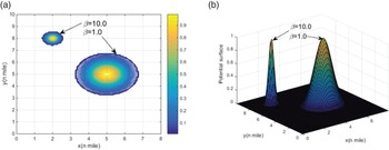
 , the flatter the potential field and the larger the action range. Figure 1 shows the different action ranges and potential surfaces for different ${\boldsymbol{\beta}_{\boldsymbol{i}}}$
 . The potential field reaches the maximum value of 1 ⋅ 0 at position ${p_i}({x_i},{y_i})$
 and approaches 0 ⋅ 0 at positions far away from ${p_i}({x_i},{y_i})$
 .
Potential field for point objects with different values of ${\boldsymbol{\beta}_{\boldsymbol{i}}}$ : (a) potential contours, (b) potential surfaces

2.2 EPF modelling for line objects
Line objects provided by the electronic chart are represented by a group of line segments. Among the anticlockwise sorted line segments, if the i-th line segment $\mathop {{p_i}{p_{i + 1}}}\limits^ \to$ starts from ${p_i}({x_i},{y_i})$
 and ends at ${p_{i + 1}}({x_{i + 1}},{y_{i + 1}})$
 , then the implicit function of the line segment is ${f_{\textrm{Line - }i}} = {A_i}x + {B_i}y + {C_i}$
 . For any point $p(x,y)$
 , it is on the line when ${f_{\textrm{Line - }i}} = 0$
 , or on the left side of the line when${f_{\textrm{Line - }i}} > 0$
 , or on the right side of the line when ${f_{\textrm{Line - }i}} < 0$
 . The potential field of the line object can be expressed as:

where ${\boldsymbol{\gamma}_{\boldsymbol{i}}}$ is the i-th positive parameter of the line segment that determines the influence range of the line; the smaller the value of ${\boldsymbol{\gamma}_{\boldsymbol{i}}}$
 means the flatter the potential field and the larger the action range of the line; otherwise, a larger value of ${\boldsymbol{\gamma}_{\boldsymbol{i}}}$
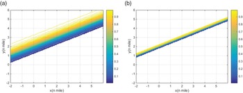
 means a steeper potential field and a smaller action range of the line. As shown in Figure 2, when ${f_{\textrm{Line - }i}} = 0$
 , the point $p(x,y)$
 is on the line segment, and the potential field value is 0 ⋅ 5. If ${f_{\textrm{Line - }i}} > 0$
 , the potential field value is larger, and the maximum is 1 ⋅ 0. If ${f_{\textrm{Line - }i}} < 0$
 , the potential field value is smaller, and the minimum value is 0.
Potential fields for line objects: (a) ${\boldsymbol{\gamma}_{\boldsymbol{i}}}\textrm{ = }1.0$ , (b) ${\boldsymbol{\gamma}_{\boldsymbol{i}}}\textrm{ = 5}.0$


2.3 EPF modelling for face objects
If there are N face objects in the 2D plane, then each face object is represented by a group of anticlockwise sorted line segments. If we can obtain the mathematical expression ${F_i}(x,y)$ of the face object and let the points inside the polygon fulfil the expression ${F_i}(x,y) < 0$
 , let points on the edge fulfil the expression ${F_i}(x,y) = 0$
 , and let points outside the polygon fulfil the expression ${F_i}(x,y) > 0$
 , then the potential field of face object can be expressed as:

where ${\boldsymbol{\alpha}_{\boldsymbol{i}}}$ is the positive parameter of the i-th face object. Similarly, the smaller the value of ${\boldsymbol{\alpha}_{\boldsymbol{i}}}$
 , the flatter the potential field and the larger the action range of the face object. Otherwise, the larger the value of ${\boldsymbol{\alpha}_{\boldsymbol{i}}}$
 , the steeper the potential field and the smaller the action range of the face. If ${F_i}(x,y) = 0$
 , point $p(x,y)$
 is on the edge of the face object, and the potential field value is 0 ⋅ 5. If ${F_i}(x,y) > 0$
 , $p(x,y)$
 is outside the face object, then the potential field value is smaller, and the minimum is 0. If ${F_i}(x,y) < 0$
 , $p(x,y)$
 is inside the face object, the potential field value is larger, and the maximum is 1 ⋅ 0.
A MASS should maintain a safe distance from islands or shallow waters when navigating. However, sometimes it is required to navigate inside certain navigable regions and maintain a safe distance from the edges of the region, such as navigating in channels, traffic separation schemes, or other safe navigable areas. The potential field of the face object can be expressed as:

where the inside of the face is navigable, the potential field is smaller, and the minimum is 0; whereas the outside of the face is unnavigable, and the potential field approaches 1 ⋅ 0 if it is far away from the face object.
2.4 EPF of the entire static environment
If there are M, N, and Q point objects, line objects, and face objects around the MASS, respectively, then the total potential field of the entire static environment can be obtained by adding the potential field generated by the point objects, line objects, and face objects. The environmental potential field at $p(x,y)$ can then be expressed as:

Each spatial object has a unique attribute for navigation. By setting the appropriate values for $\boldsymbol{\beta}$ , $\boldsymbol{\gamma}$
 , and $\boldsymbol{\alpha}$
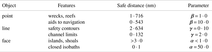
 to specify the action ranges of the object, the recommended parameter for each spatial object and the safe distance to be maintained are listed in Table 1.
Recommended $\boldsymbol{\beta}$ , $\boldsymbol{\gamma}$
 , and $\boldsymbol{\alpha}$
 values for different objects

3. R-function representation for geometric object
3.1 Theory of R-function
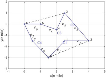
For the geometry in the 2D plane (as shown in Figure 3), the equation for each edge can be expressed by an implicit function ${f_i}(x,y) = 0$ . The implicit function separates the plane into two half-spaces. The points on the line fulfil the expression of ${f_i}(x,y) = 0$
 , and the points in the half-space fulfil the expression of ${f_i}(x,y) > 0$
 or ${f_i}(x,y) < 0$
 . For an arbitrary closed shape, if the vertices are sorted anticlockwise, the inner part of the shape can be expressed by the left half-space of each edge (${f_i}(x,y) < 0$
 ). Therefore, the R-function can be used to express the region enclosed by two inequalities as function operations; through algebra operations to the implicit function of each edge, we can obtain the expressions $F(x,y) < 0$
 , $F(x,y) = 0$
 , and $F(x,y) > 0$
 to express that point $p(x,y)$
 is internal, boundary, or external to the geometric object.
Convex hull and side-chains of polygon B

The R-function is a real-value function characterised by a property that is completely determined by the sign of its arguments rather than its value. Rvachev presented a series of useful R-functions with sufficient completeness, where ${R_a}$ is an R-function system:

where $a = a(x,y)$ is an arbitrary continuous and symmetric function and fulfilled by the expression $- 1 < a(x,y) \le 1$
 . The symbol ${\pm}$
 denotes the R-conjunction and R-disjunction. If $a = 0$
 or $a = 1$
 , the widely used ${R_0}$
 system and ${R_1}$
 system are as follows:


Compared with other R-function systems, the ${R_0}$ system is differentiable except at the origin, and the calculation is simple. In this study, we select the ${R_0}$
 system to represent the geometric objects.
The implicit function based on the aforementioned approach cannot accurately calculate the signed distance between a space point and an object boundary, so normalised function was introduced into the geometric object expression. For line segments expressed as ${f_{\textrm{Line - }i}} = {A_i}x + {B_i}y + {C_i}$ , its normalised function is:

3.2 R-function representation for geometric objects
Arbitrary geometric objects can be expressed by several basic primitives through regular Boolean operations (‘intersection’ or ‘union’). The geometric object B can be expressed in the following form:

where ${B_i}$ ($i = 1,2, \cdots ,n$
 ) is a basic primitive and F is a regular Boolean function with operations of ${ \cap ^\ast }$
 , ${ \cup ^\ast }$
 , and ${ - ^\ast }$
 . If the logical operations ${\wedge}$
 , ${\vee}$
 , and $\neg$
 are used to displace the Boolean operations, then F becomes a logical function. Combined with the definition of the R-function, the geometric object B can be expressed as follows:

where the basic primitive ${B_i}$ is the half-space of the geometric object expressed by an implicit function ${f_i}(x) \le 0$
 . If the signed distance function ${f_i}(x)$
 for basic primitive ${B_i}$
 is:

then Equation (10) can be written as:

According to Equation (13), given a continuous function $f(x)$ and its correlation function $F({X_1},{X_2}, \cdots ,{X_n})$
 , the geometric object B can be expressed as:

where ${f_i}(i = 1,2, \cdots ,n)$ is a real continuous function, and f is the implicit function of B. Because the geometric objects in this study are all in the 2D plane and without any curves or surfaces, the implicit function of the geometric object is accurate for expressing the object. Otherwise, the implicit function approximately expresses the geometric object.
3.3 Discrete-convex hull method
The expression of the geometric object using R-function is a semi-analytical solution based on its constructive solid geometry(CSG) model, and the implicit function can be used to accurately express the geometric object in the 2D plane. CSG representations usually have various logical and implicit functions, but they have the same logical functionality. In fact, the automatic generation of a CSG representation for an overly complex object is an intractable task. However, existing algorithms can automatically generate the CSG representations for polygonal regions. A polygonal region can be automatically divided into side-chains with the intersection of convex hull vertices. The intersection of the half-space defined by side-chains can then be adopted to express a polygonal region, whereas the half-space is represented by the intersection or union of the edges. If the intersection of the two edges is concave, the half-space is the union; otherwise, it is the intersection. The region B shown in Figure 3 has the logical function $B = {C_1} \wedge {C_2} \wedge {C_3} \wedge {C_4}$ . Here, ${C_1} = {e_1} \vee {e_2}$
 ,${C_2} = {e_3}$
 ,${C_3} = {e_4} \vee ({e_5} \wedge {e_6})$
 and ${C_4} = {e_7} \wedge {e_8}$
 .
The aforementioned approach for dealing with a geometric object is referred to as the discrete-convex hull method. As mentioned previously, the face objects in this study are represented by a group of anticlockwise sorted line segments in the 2D plane; their implicit functions are accurate for expressing geometric objects. Therefore, the implicit function of a geometric object has a value of 0 at the boundary of the object, and the internal and external points have values <0 and >0, respectively.
3.4 EPF modelling procedure for complex face object
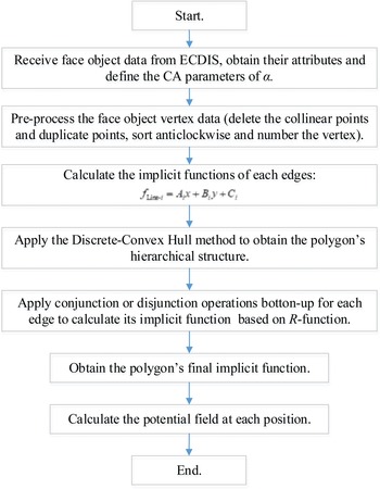
The procedure of EPF modelling for complex face objects can be summarised as follows (as shown in Figure 4). First, data on the face objects are received from ECDIS, the attributes are obtained, and the CA parameters of $\alpha$ are defined to specify their action ranges. Second, the vertices of the face objects are pre-processed, including deleting collinear or duplicate points, sorting anticlockwise, and numbering. Third, the implicit functions of each edge were calculated, and the discrete-convex hull method is applied to obtain the hierarchical structure of the polygon. Fourth, the conjunction or disjunction operation is applied bottom-up for each edge to obtain an implicit function based on the R-function. Finally, the implicit function of the polygon is obtained, and the potential field at each position is calculated.
EPF modelling procedure for complex face object

4. Path planning
CA and path planning for MASS is a complex system that is constrained by COLREGS and should cope with static and dynamic environments in real time. Following the work of Lyu and Yin (Reference Lyu and Yin2019b, Reference Lyu and Yin2018b), we used a path-guided hybrid APF method (PGHAPF) to realise MASS CA and OA.
4.1 Modelling of motions of MASS
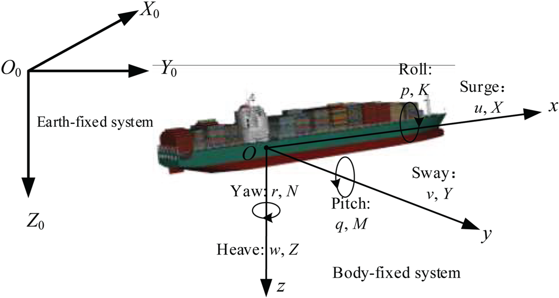
To describe the motion of a MASS in CA, the Earth- and body-fixed coordinate systems were constructed as shown in Figure 5. The vector $\boldsymbol{\eta} = {[{x,y,z,\phi ,\theta ,\psi } ]^\textrm{T}}$ represents the position and altitude of MASS in the Earth-fixed system, and the vector $\boldsymbol{\nu} = {[{u,v,w,p,q,r} ]^\textrm{T}}$
 represents the speed and rotation speed in the body-fixed system. The 6-DOF mathematical model of the MASS can be expressed as:

where $m = {\rho _s}\nabla$ represents the mass of the vessel; ${\rho _s}$
 is the seawater density; $\nabla$
 is the displacement; ${m_x}$
 , ${m_y}$
 , and ${m_z}$
 denotes the mass added to the vessel; ${I_{xx}}$
 , ${I_{yy}}$
 , ${I_{zz}}$
 , ${J_{xx}}$
 , ${J_{yy}}$
 , ${J_{zz}}$
 denote the moments and added moments of inertia; the subscripts H and G represent the viscous hydrodynamics and hydrostatic forces exerted on the naked hull; the subscripts P and R are the forces and moments generated by the propeller and rudder; the subscript ‘Env’ denotes the external disturbance forces induced by wind, wave, and current.
Coordinate system of ship motion

4.2 Modified APF model
The attractive ${F_{\textrm{att}}}$ and repulsive ${F_{\textrm{rep}}}$
 forces exerted on the ship under varying conditions were established by referring to the work of Lyu and Yin (Reference Lyu and Yin2018a, Reference Lyu and Yin2019a). Because of the numerous and undefined parameters for CA, the CA results have no direct relationship with the CA parameters, and the cited work of Lyu and Yin is therefore incomprehensible and unacceptable for navigators. As the DCPA-TCPA is the essential criterion rule for ‘risk of collision’ in navigation, we modified the negotiation CA repulsive force ${F_{\textrm{rd}}}$
 and emergency CA repulsive force ${F_{\textrm{re}}}$
 as follows:


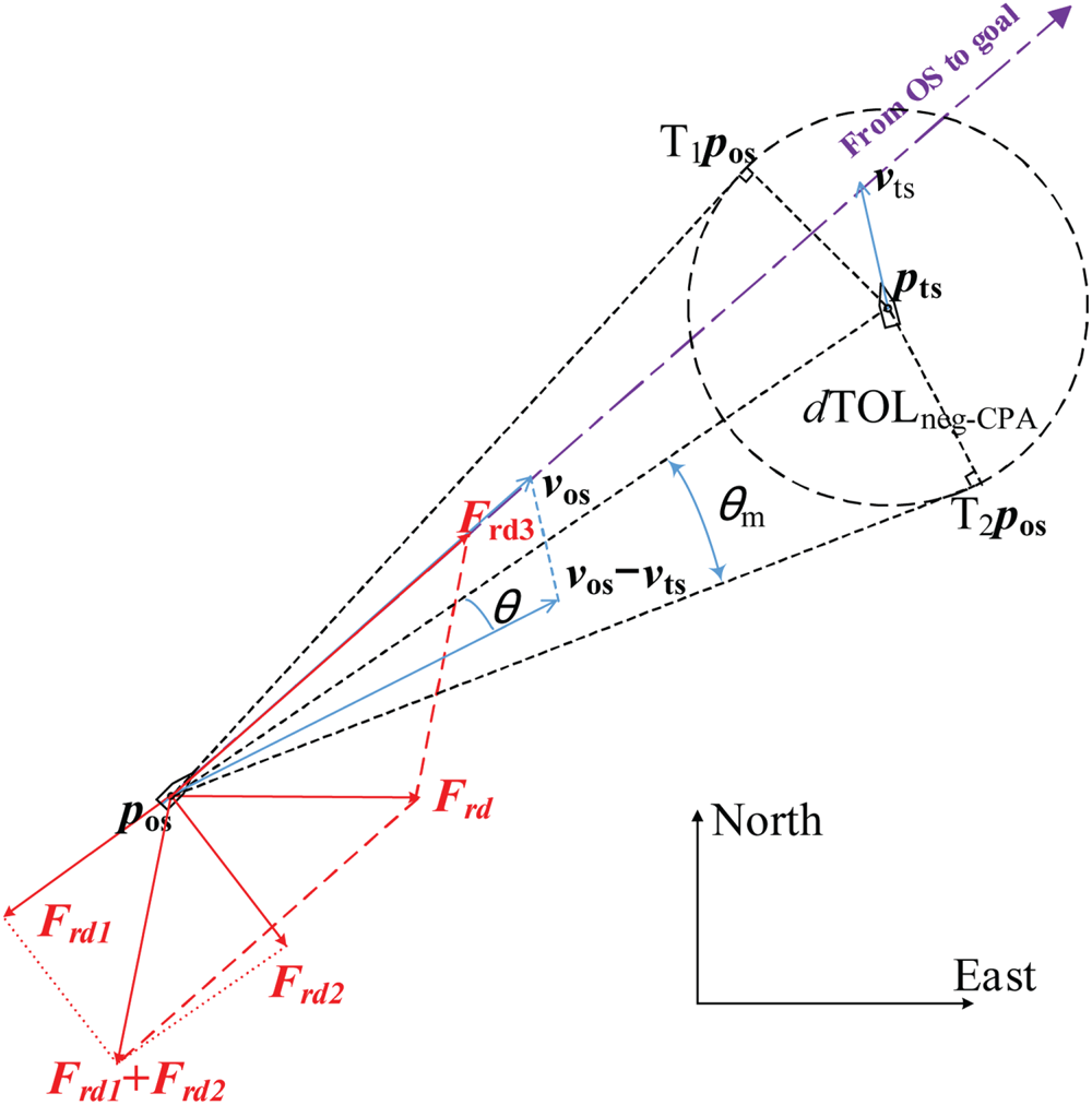
where the direction and significance of each force are shown in Figure 6. The term ${\boldsymbol{n}_{ot}}$ denotes a unit vector pointing to TS or obstacle from own ship (OS); ${d_g}$
 is the distance between OS and the goal; d is the distance between OS and TS; ${\theta _\textrm{m}}$
 is the angle between any tangent line (T1pos or T2pos) and the relative position vector ${{\boldsymbol p}_{{\boldsymbol os}}}{{\boldsymbol p}_{{\boldsymbol ts}}}$
 ;$\theta$
 is the angle between the relative position vector ${{\boldsymbol p}_{\textrm{ot}}}$
 (${{\boldsymbol p}_{\textrm{ot}}} = {{\boldsymbol p}_{\textrm{ts}}} - {{\boldsymbol p}_{\textrm{os}}}$
 ) and the relative speed vector ${{\boldsymbol v}_{\textrm{ot}}}$
 (${{\boldsymbol v}_{\textrm{ot}}} = {{\boldsymbol v}_{\textrm{os}}} - {{\boldsymbol v}_{\textrm{ts}}}$
 ). The risk of collision occurs when the extension line of ${{\boldsymbol v}_{\textrm{os}}}$
 crosses the circle of radius $d\textrm{TO}{\textrm{L}_{\textrm{neg - CPA}}}$
 ($\theta < {\theta _\textrm{m}}$
 ); otherwise, the OS can pass through the TS with a safe distance larger than $d\textrm{TO}{\textrm{L}_{\textrm{neg - CPA}}}$
 . Because the algorithm works on a 2D Cartesian system, we use the Euclidean distance rather than measuring the distance with the haversine formulas.
Repulsive forces for TS

Terms ${d_{\textrm{emg}}}$ and ${d_{\textrm{neg}}}$
 represent the distance criterion of emergency CA and negotiation CA, respectively, $d\textrm{TO}{\textrm{L}_{\textrm{neg - CPA}}}$
 and $t\textrm{TO}{\textrm{L}_{\textrm{neg - CPA}}}$
 denote the distance and time criteria of negotiation CA, respectively, and $d\textrm{TO}{\textrm{L}_{\textrm{emg - CPA}}}$
 and $t\textrm{TO}{\textrm{L}_{\textrm{emg - CPA}}}$
 represent the distance and time criteria of emergency CA, respectively. Because all the CA parameters have actual meanings in navigation, and the CA results correspond well to the CA parameters, the modification of the repulsive force model can be comprehended and accepted by navigators.
If there are N TSs, the total repulsive force can be obtained by adding the repulsive forces generated by each TS. The ship will take the corresponding CA actions under the resultant ${F_{sum}}$ for varying conditions and reach the goal. Based on the calculation of attractive and repulsive forces, the total virtual force exerted on the ship can be obtained as:

5. Tests and results
5.1 EPF modelling for face objects
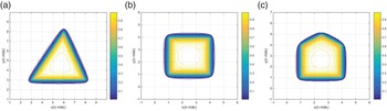
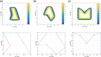
EPF modelling of convex polygons is uncomplicated because the implicit functions of polygons can be obtained using a one-layer intersection operation (${\wedge}$ ). The potential field at any position generated by the polygons can be obtained as shown in Figure 7.
Potential fields generated by convex polygons ($\boldsymbol{\alpha}$ = 10 ⋅ 0): (a) triangle, (b) quadrangle, (c) pentagon

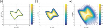
If the polygon includes one or more concave points, the discrete-convex hull method should be applied to obtain its hierarchical structure; the implicit function can then be obtained bottom-up based on the R-function theory. There is only one concave point in Figures 8(a) and 8(b), and the implicit functions of the polygons can be obtained using a two-layer discrete-convex hull calculation, whereas the polygon in Figure 8(c) requires a three-layer discrete-convex hull calculation.
Potential fields generated by concave polygons ($\boldsymbol{\alpha}$ = 10 ⋅ 0): (a) pentagon, (b)hexagon, (c) heptagon

Figure 9 shows the potential field with different values of $\boldsymbol{\alpha}$ . It is obvious that a smaller value of $\boldsymbol{\alpha}$
 generates a larger action range of the potential field (the navigable area is smaller around the object). The approach proposed in this study provides an edge-smoothed potential field. The potential field was well-smoothed even around the sharp vertices, which is beneficial for the OA of the MASS.
Potential fields with different $\alpha$ values: (a) $\boldsymbol{\alpha}$
 = 50 ⋅ 0, (b) $\boldsymbol{\alpha}$
 = 10 ⋅ 0, (c) $\boldsymbol{\alpha}$
 = 1 ⋅ 0

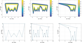
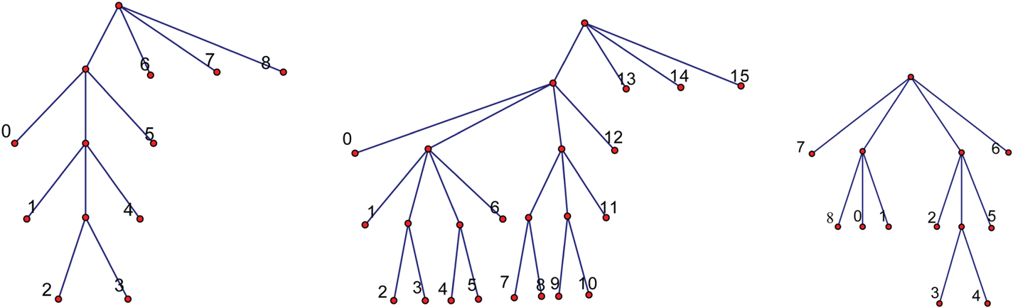
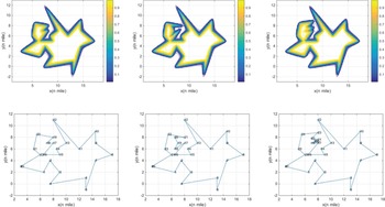
For the polygons shown in Figure 10, their hierarchical structures (as shown in Figure 11) are quite difficult to obtain owing to their complex shapes and concave-convex structures. In current research, automatic potential field modelling of these types of polygons is impractical, while the EPF can be effectively obtained in this study.
Potential fields of complex polygons ($\boldsymbol{\alpha}$ = 10 ⋅ 0)

Hierarchical structure of complex polygons

As shown in Figure 12, the hierarchical structure of the polygon becomes more complex when new vertices inserted, the potential field around the inserted points changes accordingly, and the potential field far away remains unchanged. The approach proposed in this study is proven to be feasible and reliable for solving these complicated potential field modelling problems.
Potential fields of very complex polygons

5.2 EPF modelling based on ENC data
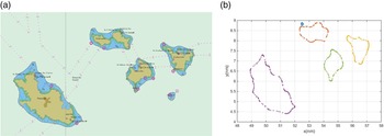
In the vector data provided by the shipboard electronic chart, the 20.0 m isobath data around Zhangzidao (Dalian, China) consist of four islands with 511 sampling points (as shown in Figure 13) (chart number = CN311001, issue date = 2015-08-18, update number = 6, update application date = 2017-12-26, scale = 1:90,000, horizontal geodetic datum = WGS 84). To demonstrate the problem-solving capability of the approach proposed in this study, a series of well-designed tests were conducted using a personal computer with an Intel(R) Xeon(R) CPU E5-1600 v3 @ 3 ⋅ 5 GHz processor, 8 GB RAM, and a 64-bit Windows 10 Professional operating system.
20 ⋅ 0 m isobath and sampling points near Zhangzidao islands: (a) 20 ⋅ 0 m isobath, (b) sampling points

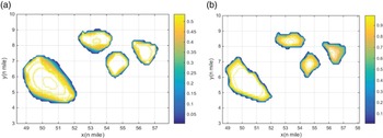
The potential field around Zhangzidao Island was generated based on the 20 ⋅ 0 m isobath data. As shown in Figure 14, a larger value of $\boldsymbol{\alpha}$ results in a larger safe navigation region for the ship, whereas a smaller value of $\boldsymbol{\alpha}$
 implies that the ship should maintain a larger distance from the islands. Although a considerable amount of data were provided by the electronic chart, and the shapes of the polygons are extremely complicated, the proposed algorithm could successfully realise the environmental potential field modelling.
Potential field of 20 ⋅ 0 m depth area: (a) $\boldsymbol{\alpha}$ = 5 ⋅ 0, (b) $\boldsymbol{\alpha}$
 = 50 ⋅ 0

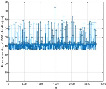
Figure 15 shows the EPF modelling time of the 20 ⋅ 0 m isobath data. The EPF calculation time for each space point is less than 0 ⋅ 1 ms in each iteration. The calculation was relatively time consuming when numerous ENC data were initially imported, because the discrete-convex hull method was applied to obtain the hierarchical structures and the implicit functions based on the R-function theory. Subsequently, the potential field calculation for each point has no direct relationship with the amount and shape of the ENC data. The approach proposed in this study has very small calculations even when operating numerous space data; thus, it can be used in real-time EPF modelling for MASS.
Time consumption of 1,000 iterations in calculating the EPF for each point

5.3 Path planning in restricted water
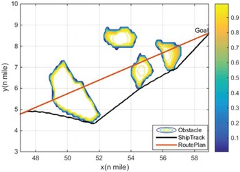
This section presents how one container ship, KangHe, was used as OS to test the OA capability based on the aforementioned 20 ⋅ 0 m isobath data. The CA parameters and initial conditions of the ship are presented in Table 2. $\boldsymbol{\alpha }$ = 50 ⋅ 0 was set for the 20 ⋅ 0 m isobath data. The ship was designed to navigate across three islands successively in accordance with the route plan, and simultaneously detect and maintain a safe distance from obstacles.
Particulars and the initial condition of KangHe

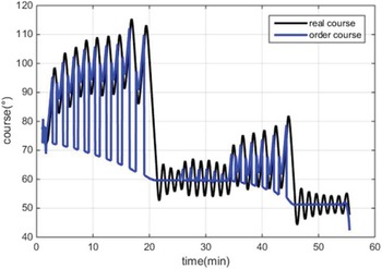
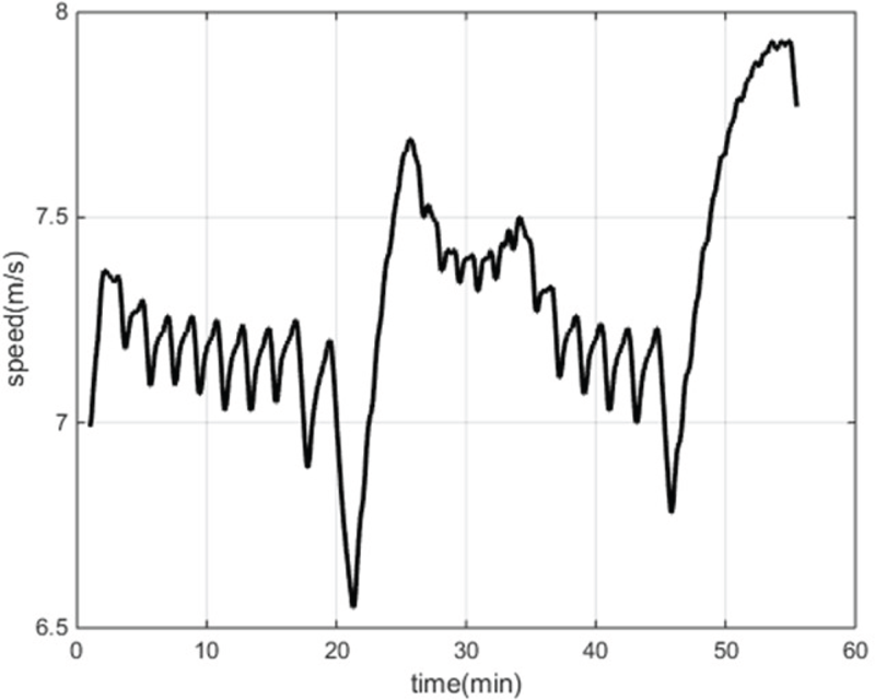
As shown in Figure 16, the OA result shows that KangHe can promptly detect the obstacles and accomplish the OA actions. Figures 17 and 18 show the course and speed changing processes during the test. In the first 20 min, KangHe detected the risk of collision with the first island and altered its course to starboard with a smaller potential field size than the port side. The speed of the ship decreased owing to the frequent operation of the rudder. At 21 min, KangHe headed for the goal with an extra left turn when it had passed the first island, and the speed increased immediately owing to the stable large rudder angle. At 25 min, KangHe started to carry out OA actions to the second and third islands in succession, and the speed of the ship decreased correspondingly owing to the frequent course alteration. At 46 min, KangHe passed and cleared all the islands and altered its course to head for the final destination.
OA result for KangHe ($\boldsymbol{\alpha}$ = 50 ⋅ 0)

Course of KangHe in OA test

Speed of KangHe in OA test

5.4 Path planning in restricted water and with multiple TSs ($\boldsymbol{\alpha}$ = 50 ⋅ 0)

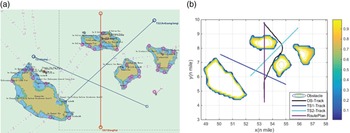
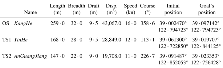
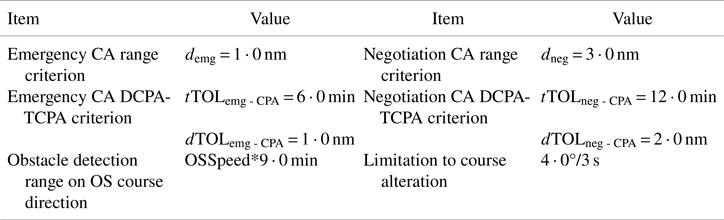
This section presents how the container ship KangHe (OS) was used as a smart ship along with two target container ships, YinHe (TS1) and AnGuangJiang (TS2), to complete the collaborative CA and OA experiment. The initial conditions and ship particulars are presented in Figure 19(a) and Table 3. $\boldsymbol{\alpha}$ = 50 ⋅ 0 was set for the 20 ⋅ 0 m isobath data, and the CA parameters are listed in Table 4.
Initial conditions of the scenario and collaborative CA results for KangHe: (a) initial scenario conditions, (b) collaborative CA and OA results

Particulars and initial conditions of ships

Parameters for CA tests

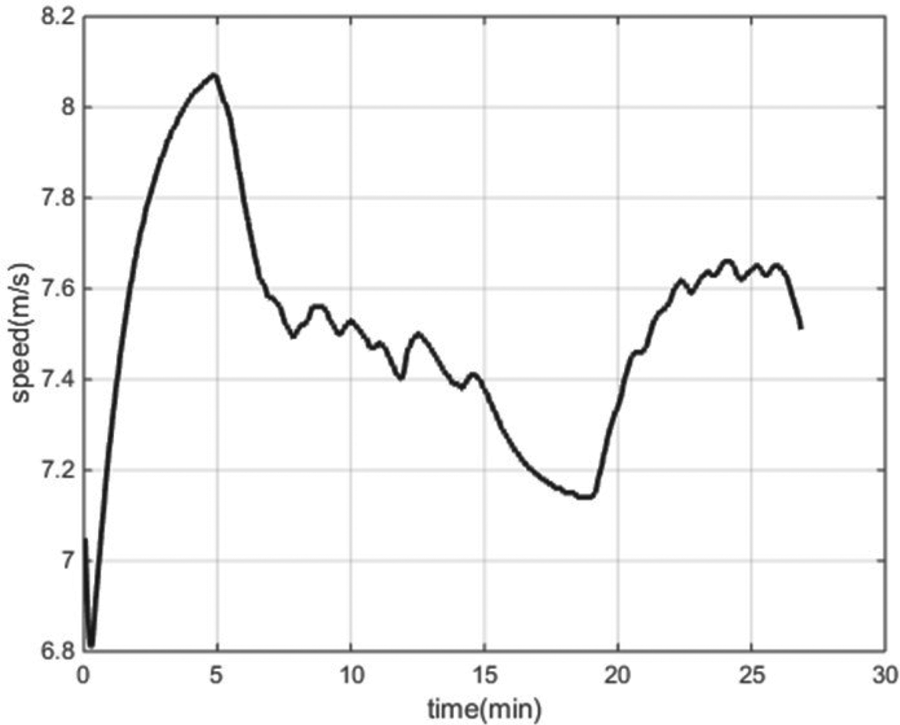
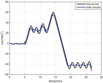
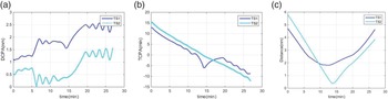
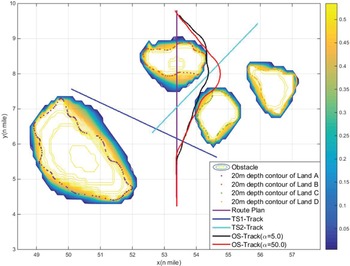
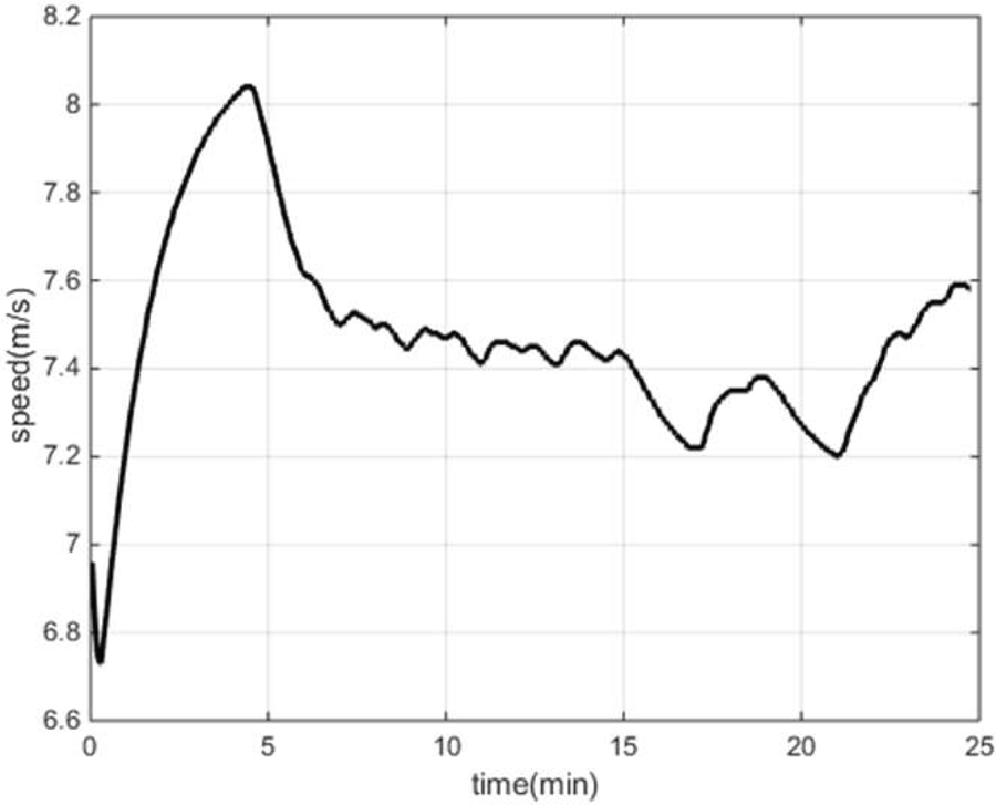
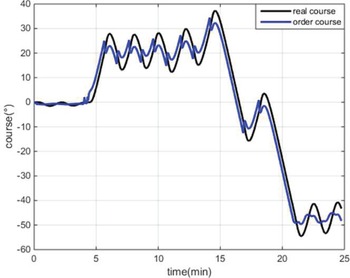
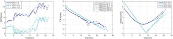
Figure 19(b) shows the collaborative CA and OA results obtained by KangHe. Figures 20 and 21 show the speed and course changing processes, respectively, and Figure 22 shows the DCPAs, TCPAs, and distances during the entire test. By analysing the results and intermediate processes, we observed that the ship navigated on the route plan at full speed in the first 5 min because there was no risk of collision between OS and TSs or obstacles. With the distances between OS and TSs decreasing, the DCPAs and TCPAs decreased accordingly; at 5 min, KangHe started to alter course to starboard as the CA criteria (Negotiation CA TCPA-DCPA and range criterion) with TS1 was fulfilled. At 7 min, the CA criteria with TS2 was fulfilled, KangHe started to carry out CA action with TS1 and TS2, and take OA actions around the islands simultaneously. At 14 min, KangHe started to head for the final destination when it had passed and cleared both TSs and obstacles.
Speed of KangHe

Course of KangHe

DCPAs, TCPAs, and distances between KangHe and TSs: (a) DCPAs, (b) TCPAs, (c) distances

According to the criteria in Table 4, KangHe should maintain a desired DCPA from all vessels and keep a safe distance of 2 ⋅ 0 nm from them. Owing to the restriction of obstacles provided by electronic chart, even though the largest CA actions were applied, KangHe passed and cleared at a distance of 1 ⋅ 81 nm from TS1 and a distance of 0 ⋅ 38 nm from TS2, respectively.
5.5 Path planning in restricted water and with multiple TSs ($\boldsymbol{\alpha}$ = 5 ⋅ 0)

We set $\boldsymbol{\alpha}$ = 5 ⋅ 0 for the 20 ⋅ 0 m isobath data to decrease the navigable area around the islands and conducted the same collaborative CA and OA experiment shown in Section 5.4. Figure 23 shows the CA results for KangHe. Comparisons with the results in Section 5.4 are shown in Figures 23–26. The results show that, in both experiments, the ship conducted the largest CA actions to maintain a relatively safe range of distance from obstacles and other ships.
Collaborative CA and OA results for KangHe

Speed of KangHe

Course of KangHe

DCPAs, TCPAs, and distances between KangHe and TSs: (a) DCPAs, (b) TCPAs, (c) distances

Through comparison with the results in Section 5.4 (as shown in Figure 26), it can be observed that a smaller value of $\boldsymbol{\alpha}$ induces a larger effective range around the obstacles while reducing the safe navigable region of the ship and restricting the scope of actions. In both experiments, KangHe started to carry out CA action with TS1 at 5 min, and then took CA action with TS1 and TS2 simultaneously. For the restriction of obstacles provided by the electronic chart, KangHe could not pass and clear the TSs at the desired safe distance of 2 ⋅ 0 nm. Because the effective range of the obstacles is larger than that in Section 5.4, the ship needs greater actions to maintain a larger distance from the islands while the action scope in relation to the other ships decreased. Finally, as listed in Table 5, KangHe passed and cleared TS1 and TS2 at distances of 1 ⋅ 72 nm and 0 ⋅ 16 nm, respectively; these distances are smaller than those in Section 5.4.
CA results for KangHe

6. Discussion
From the standpoint of engineering application, this paper proposes a novel environmental potential field modelling method based on R-function theory and within the ECDIS framework, and solves the awkward EPF modelling problems in APF-based path planning. The contributions of this study can be summarised as follows:
(1) An accurate EPF model is established based on ENC data to describe different types of obstacles, navigable areas, and non-navigable areas.
(2) A highly efficient and automatic EPF modelling method for complicated face objects is proposed based on R-function theory and discrete-convex hull technology.
(3) This study combines the accurate face object EPF model and improved APF method to realise the collaborative CA and OA.
(4) The system was developed in C++ and within the ECDIS framework. Collaborative CA and OA experiments were designed and conducted in a simulated environment to verify the effectiveness of the proposed EPF modelling method.
The proposed EPF modelling approach and path planning method were systematically tested (see Section 5). The results show that:
(1) The hierarchical structures of any complicated face object can be obtained automatically using the discrete-convex hull method, regardless of their concave-convex structures.
(2) The proposed EPF modelling method is accurate, because the data are provided by the officially released ENC data, and the R-function representation for face objects in the 2D plane is accurate.
(3) Through tests based on 20 ⋅ 0 m isobath data from Zhangzidao (Dalian, China), the proposed EPF modelling approach is proven to be accurate and reliable. As the proposed EPF modelling approach has very small calculations, it can be used in MASS real-time path planning.
(4) The collaborative CA and OA results show that the combination of the improved APF and EPF models is effective for MASS path planning, and different CA results can be obtained by setting different CA parameters for the ENC data.
For the future work, our research will be continued and improved in several ways. First, the EPF of an entire harbour will be established based on ENC data (tens of thousands of sampling points including lands, islands, navigation aids, isolated point objects, channel, etc.). Second, the current algorithm is mainly in accordance with rules 8 and 13–17 of COLREGS, and the OS acts as a give-way vessel; it is necessary to improve it to obey more rules. Third, the COLREGS-constrained APF model and EPF modelling method require more real-life tests to ensure their completeness. Fourth, we expect an early real-ship test of the proposed approach as an auxiliary CA system.
7. Conclusions
This study systematically solves the EPF modelling problems of complex geometric objects. In this study, reliable environmental data were provided by the officially released ENC data. The proposed EPF modelling method based on the R-function theory in this study can establish the potential field of any complex face object even if the object embodies a very complex concave-convex structure. The modelling procedure is simple and easy to conduct, offline extraction or mesh dividing operation of the ENC data is unnecessary, and the EPF modelling can be realised automatically without any manual intervention within the framework of the ECDIS. The proposed method is important for engineering applications of intelligent CA systems and is also a feasible path planning method for inland river ships.
Acknowledgements
This research was partially supported by: the National Natural Science Foundation of China (No. 52071049); the project ‘Intelligent Ship Testing and Verification’ (No. 2018/473); the Natural Science Foundation Guidance Project of Liaoning Province (No. 2019-ZD-0152); and the project ‘Maneuvering Simulation of Yunnan Inland Shipping Ships’ (No. 851333).
Data availability
The data used to support the findings of this study are available from the corresponding author upon request.