1. INTRODUCTION
Product development processes typically begin with a design brief that is used to drive a design process that starts with initial design concepts, usually in the form of hand-drawn sketches, and ends with a fully defined design definition that can be used to support engineering analyses and manufacturing. Computer-aided design (CAD) tools, based on the solid modeling methods reviewed by Requicha and Voelcker (Reference Requicha and Voelcker1983), provide strong support for the later stages of product design and development when the structure and shape of the design have been fixed. Support for earlier conceptual design stages, when both the structure and shape of the design are still fluid, demands a new kind of CAD solution that does not require an unambiguous representation of the designed shape, yet recognizes equivalency of such representations and allows multiple reinterpretations. This new generation of solution, so-called “computational design synthesis” systems, needs to support designers' ways of thinking and working so that they enhance design creativity, for example, by offering nonobvious design alternatives that were not originally recognized by the designer. The latter is akin to pencil and paper processes identified by Stiny (Reference Stiny1991).
In this article we use the term spatial as opposed to shape grammars because the definition of shape grammar has traditionally implied a maximal element representation that supports emergence, that is, recognition and manipulation of shapes that emerge through shape computation but are not explicitly represented. Although maximal representations are theoretically possible for the solids and surfaces that typify industrial product design activities, a key and presently unresolved prerequisite to their implementation lies in recognizing equivalent boundaries of these shape elements, namely, surfaces and curves respectively. As a result, some of the systems reviewed in this paper cannot, strictly speaking, be regarded as shape grammar implementations because they use other fundamental representations for shapes, such as sets of parametrized objects, graphs, or pixels. The potential of spatial grammars (including shape, set, and graph grammatical approaches) as a theoretical framework on which computational design synthesis systems might be built has been demonstrated through experimental research prototypes since the 1970s. Over the decades, the term spatial grammar has been applied to unrelated work in computer graphics and computational geometry, as well as design grammars that use nonmaximal element representations (including several reviewed later in this paper; Krishnamurti & Stouffs, Reference Krishnamurti and Stouffs1993). In addition, design grammars have been used as an educational device to support students in understanding how design alternatives might be generated and to build their self-awareness with respect to the shape generation processes they use. In this paper we review progress made in achieving usable computational design synthesis systems focusing on spatial grammars. Regarding the journey to computational design synthesis as a design exercise in its own right, we consider requirements for spatial grammar based computational design synthesis systems in the light of requirements for conceptual design tools, and identify future research directions in both research and design education. On this basis, we review currently available systems in terms of four key characteristics: underlying representation and algorithms, user interaction and interface, and two aspects of application support, support for particular problem domains and support for specific stages of the product development process.
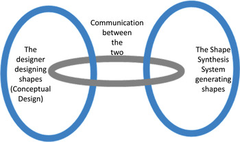
The overarching structure of the paper is based on the framework shown in Figure 1. It can be seen that this regards, as two separate processes, a human activity of designing shapes and a computational system that computes shapes; the two processes are connected by a third, communication, process. In Section 2, requirements for conceptual design to support designers designing shapes are introduced and related to requirements for grammar-based design systems. This concludes with a collection of requirements for usable spatial grammar based computational design system implementations. A review of the development of spatial grammar based design systems with respect to these requirements is given in Section 3. Section 4 draws from discussions at the Design Computing and Cognition 2010 (DCC'10) workshop on grammar implementations (DCC10 grammars) and identifies future research areas.
A framework for computer-aided shape generation activities. Reprinted from “Design Synthesis and Shape Generation,” A. McKay, S.C. Chase, S.W. Garner, I. Jowers, M. Prats, D.C. Hogg, H.H. Chau, A. de Pennington, C.F. Earl, and S. Lim, Reference McKay, Chase, Garner, Jowers, Prats, Hogg, Chau, de Pennington, Earl, Lim and Inns2009, In Designing for the 21st Century: Interdisciplinary Methods and Findings (Inns, T., Ed.), pp. 304–321. Copyright 2009 by Gower Publishing. Reprinted with permission. [A color version of this figure can be viewed online at http://journals.cambridge.org/aie]

2. REQUIREMENTS FOR SPATIAL GRAMMAR BASED DESIGN SYSTEMS
2.1. Requirements for computational conceptual design tools
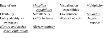
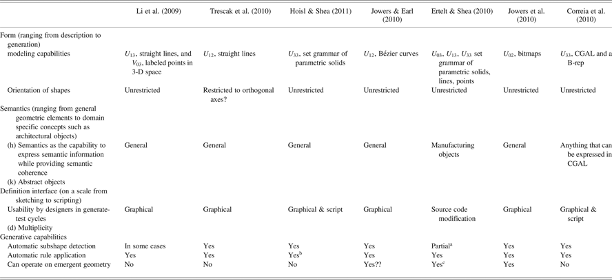
Iordanova and Mueller (Reference Iordanova and Mueller2010), in their workshop at DCC'10 on bridging the gap between abstract requirements and concrete implementation strategies for computational conceptual design tools, provide a collection of requirements for such tools. The names of these requirements are reproduced in Table 1. The use of spatial grammars in the realization of computational conceptual design tools demands robust and complete implementations. In the long term a given spatial grammar based kernel could be used to underpin multiple conceptual design tools and applications: akin to the three-dimensional (3-D) solid modeling kernels identified by Requicha and Voelcker (Reference Requicha and Voelcker1983). The requirements in Table 1 that are most applicable to such a kernel are highlighted in italic; these requirements are the focus of this paper.
Requirements for computational conceptual design tools

Note: The requirements are according to Ordanova and Mueller (2010). Those requirements most applicable to a spatial grammar based kernel are underscored and italic.
Modeling capabilities relate to the ability of a system to support designers in expressing design concepts. For the design of physical products, this relates to both the capabilities of the shape representation scheme underpinning the system and the ability to represent other attributes of a design concept, for example, material and surface properties. Similarly semantics, the ability to associate semantic information with a design concept is closely related to the underlying representation scheme used. Entity identity (from entity identity vs. emergence) relates to the provision of multiple presentations of a given concept. It aligns with the structure provided within the integrated resources of the STEP standard (ISO10303-1; ISO, 1994) that, if applied to support communication between conceptual design systems, would allow a given design concept to have multiple representations and, for each representation, multiple presentations. If the spatial grammar based design solution is regarded as a kernel then this would not be regarded as a key requirement. However, emergence is regarded as a requirement because it places demands on the underlying representation scheme to allow multiple interpretations in order that the semantics of aspects of a given design might be changed and used in ways not possible in the original representation. Whether entity linkages are regarded as requirements for a kernel depends on the level of detail needed in the linkages between concepts. They are included here because a key benefit of grammar-based kernels is the ability to capture traceability between generated concepts.
Within spatial grammar based systems, linkages between generated concepts and the grammars from which they were generated can be used to support the exploration of both design histories and design spaces. For example, the history of shapes in the style of a given brand might be explored through the way in which the grammars used to both define the style and generate the designs have changed over time. With respect to the exploration of design spaces, a design language (defined using a grammar) can be regarded as a definition of a potentially vast design space. The generative capability of a spatial grammar based system results in populations of generated design concepts that sit within such spaces. With appropriate exploration tools, ranging from interactive user generation to automated search methods, these design spaces can be explored by users. (Re)generativity relates to the ability of a system to recreate a design concept, for example, to support the building of understanding of a complex shape.
2.2. Requirements for spatial design grammar implementations
The use of spatial design grammars in the realization of computational conceptual design tools demands robust and complete implementations. A number of authors have identified requirements for shape grammar implementations, for example, Gips (Reference Gips1999) and Chau et al. (Reference Chau, Chen, McKay, de Pennington and Gero2004). In this paper the following requirements for spatial grammar-based implementations, derived from both Gips and Chau et al., are used to characterize an idealized general spatial design grammar implementation:
1. form (ranging from description to generation and including parametric elements):
• enabling automatic subshape recognition and shape emergence
• enabling automatic shape recognition under Euclidean transformations
• allowing parametric shape rules
• enabling automatic shape recognition for parametric shape grammars
• enabling automatic rule application
• supporting both surfaces and solids
• allowing curvilinear basic elements
2. orientation of shapes
3. semantics (ranging from general geometric elements to domain specific concepts)
4. definition interface (on a scale from sketching to scripting) and its usability by designers in generate-test cycles
5. incorporating an intuitive user interface
6. providing measures for ranking designs for automated selection
7. providing unambiguous interpretation of resulting designs for downstream applications and their physical realization
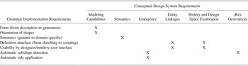
These requirements are related (Table 2) to the conceptual design system requirements introduced in Section 2.1, to provide a set of requirements for spatial grammar based conceptual design systems. In the long term, spatial grammar-based kernels could be used to underpin multiple conceptual design tools and applications, which are akin to the 3-D solid modeling kernels identified by Requicha and Voelcker (Reference Requicha and Voelcker1983). Relationships between the requirements for conceptual design systems and those for spatial design grammar implementations are summarized in Table 2.
Relationships between requirements for conceptual design systems and design grammar implementations

3. REVIEW OF SPATIAL GRAMMAR BASED IMPLEMENTATIONS
The history of shape grammar implementations can be broadly categorized by the foci of the systems that were developed. Early work focussed primarily on general two-dimensional (2-D) shape interpreters. For example, Carlson's Grammatica (Reference Carlson1993) supported the generation and exploration of U 12Footnote 1 floor plans. Such systems were typically limited by the kinds of shapes that they supported, in this case 2-D shapes including parametric shapes, and showed potential for extension to more complex 3-D design problems. At a similar time, Heisserman (Reference Heisserman1991, Reference Heisserman1994) developed a 3-D system, including parametric rules, called Genesis, that generated Queen Anne houses and a variety of other geometric forms, for example, Sierpinski sponges, fractal-like mountains, and SLA support structures. This was later extended at Boeing to the generation of aircraft systems tubing and components, thus demonstrating its generality as well as becoming the first commercially used grammar-based system (Heisserman, 1994).
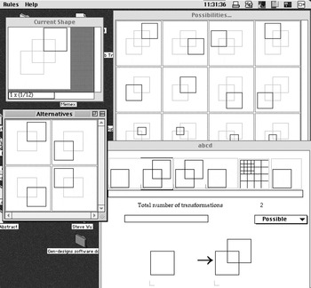
In contrast, Agarwal and Cagan (Reference Agarwal and Cagan1998) describe a design-specific coffee maker grammar and implementation, and Pugliese and Cagan (Reference Pugliese and Cagan2001) introduce their Harley–Davidson motorcycle grammar, which were typical of shape grammar implementations at the time. For the purposes of this paper we argue that a spatial grammar implementation suitable for use in design needs not only to support the kinds of shape that occur in the design domain of interest but also to align with the ways in which designers think and the processes that underpin their design practices. For example, Tapia's (1999) GEdit system interface is illustrated in Figure 2. GEdit was an early example of a shape grammar system that both considered the designer's process, workflow and practice in its interface and supported emergence.
The GEdit system user interface. Reprinted from “A Visual Implementation of a Shape Grammar System,” by M. Tapia, Reference Tapia1999, Environment and Planning B: Planning and Design 26, 59–73. Copyright 1999 by Pion. Reprinted with permission.

The focus of this paper is a review of spatial grammar based implementations of computational design synthesis focusing mainly on those presented in the DCC'10 workshop (DCC10 grammars) as a strong indication of the current state of the art. The challenge is to develop conceptual design tools that support designers' ways of thinking and working and enhance creativity, for example, by offering design alternatives difficult or not possible to identify without the use of such tools. In this section we introduce requirements for conceptual design tools and then explain how spatial grammars, as an underlying formalism and technology, might contribute in responding to these requirements.
Gips (Reference Gips1999) identifies a number of key tasks that shape grammar systems could support the following:
• generation (design): generating designs using a spatial grammar interpreter (the most common feature of spatial grammar-based implementations)
• parsing (analysis): determination of whether a design is in the language of a specified shape grammar (a difficult problem with few implementations addressing this)
• inference (grammar construction): generation of a grammar from a given set of shapes/designs (even more difficult; possible research could look at identifying features that could be used to build grammars)
• development (designer's aid): environments for designing shape grammars (e.g., with built-in drawing editors or links to CAD software; many recent systems include this)
This paper focuses on the first and last points, that is, “generation” and “development,” because this is where most research activity has been in the past 10 years. “Parsing” and “inference” are important issues that remain largely unresolved with little research to date.
Representative systems (Table 3), presented in the DCC'10 workshop on which this paper is based (DCC10 grammars), are described in four broad aspects, as identified by Chase (Reference Chase2010):
1. representations and algorithms for geometry, other design attributes, and control
2. user interaction/interface
3. implementations that deal with specific design problems
4. integration into design and product development processes
Summary of reviewed systems
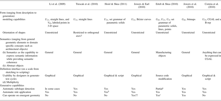
Note: CGAL, Computational Geometry Algorithms Library; B-rep, underlying geometric representation.
aThe system could be used to test the subshape relation, but it is not used in this application area.
bThere is automatic rule matching, including translation and rotation as well as parametric relations, but no subshape detection. It is a set grammar.
cThe system takes the shape as it is and not as a set of elements
3.1. A prototype system for developing 2-D and 3-D shape grammars
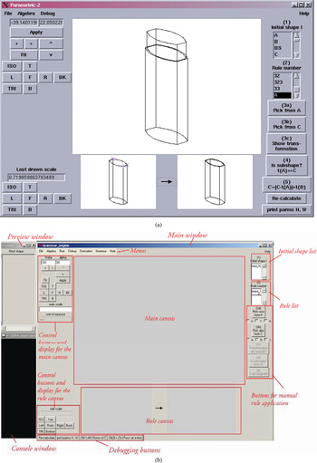
Li et al. (Reference Li, Chau, Chen and Wang2009) introduced a 3-D shape grammar interpreter that builds on the system reported by Chau et al. (Reference Chau, Chen, McKay, de Pennington and Gero2004). Li et al.'s system (shown in Fig. 3) is built on a U 13 shape representation with no restrictions on the orientation of the shape elements; the shape elements themselves can be straight lines, arcs, and labeled points. The system anticipates a future where a key aspect of a design activity will lie in the development of grammars from which design alternatives might be generated. As such, the focus of the system is to support designers in creating and developing their own grammars as an integral part of a design activity through a graphical user interface (GUI). It can be seen from Figure 3b that the system supports the definition of rules that can then be applied and the results previewed. The system supports the development of general purpose 2-D and 3-D grammars made from the supported shape elements. In the context of product design and development processes, the system is suited for use early in such processes when alternative design shapes are under consideration. The inclusion of an AutoCAD applet within the system supports the transfer of design shapes to conventional 3-D solid modeling systems using the DXF format. Although limited to lines and arcs, and so requiring human intervention to produce solids data, this provides a mechanism for the integration of shape-related data generated by the system into downstream product development processes such as analysis and manufacturing.
The three-dimensional shape grammar interpreter (a) as a screenshot from a 3-D interpreter and (b) as an annotated screenshot from the SG development system. (a) Reprinted from “Evaluation of a 3D Shape Grammar Implementation,” by H.H. Chau, X.J. Chen, A. McKay, and A. de Pennington, 2004, Design Computing and Cognition ’04: Proc. 1st Int. Conf. Design Computing and Cognition (Gero, J.S., Ed.), pp. 357–376. Copyright 2004 by Kluwer. Reprinted with permission. (b) Reprinted from “A Prototype System for Developing Two- And Three-Dimensional Shape Grammars,” by A.I.-K. Li, H.H. Chau, L. Chen, and Y. Wang, 2009, Proc. 14th Int. Conf. Computer-Aided Architectural Design Research in Asia, pp. 717–726. Copyright 2009 by CAADRIA. Reprinted with permission. [A color version of this figure can be viewed online at http://journals.cambridge.org/aie]

3.2. Shape grammar interpreter for rectilinear forms
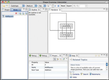
Trescak et al. (Reference Trescak, Esteva and Rodriguez2010) introduced a system that supports U 12, straight line, shape elements whose orientation is restricted to two orthogonal axes. The user interface for the system is illustrated in Figure 4. As in Li et al.'s (2009) 3-D shape grammar interpreter, the system supports designers in both developing grammars and previewing the kinds of shape that might be generated using the grammar. Three kinds of rules (addition, substitution, and modification) are supported, and individual rules can be labeled and defined either directly or parametrically. Users interact with the system through the GUI shown in Figure 4. Although not limited to a specific design domain, the system is presently limited to designs that can be represented rectilinearly. In the context of a product development process, the system does not include a capability to translate shapes into formats that can be used by commercially available 3-D CAD systems. However, given that the system is open source and the shapes that can be represented are a subset of those supported by Li et al. (Reference Li, Chau, Chen and Wang2009), the addition of such a similar, DXF-like, interface is likely to be technically feasible.
A screenshot from the SGI(2) system. Reprinted from “Shape grammar interpreter for rectilinear forms,” by T. Trescak, M. Esteva, and I. Rodriguez, 2010, Proc. 4th Int. Conf. Design Computing and Cognition. Copyright 2010. Reprinted with permission. [A color version of this figure can be viewed online at http://journals.cambridge.org/aie]

3.3. A 3-D spatial grammar interpreter for CAD
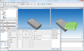
An interactive 3-D spatial grammar interpreter was presented by Hoisl and Shea (Reference Hoisl and Shea2011). The approach and prototype implementation have resulted from investigations on requirements for the integration of spatial grammars as a standard module within a CAD tool. Targeted at supporting mechanical design, which is heavily focused on the generation and manipulation of solids, it takes a set grammar approach using a vocabulary of parametrized solid primitives in algebra U33, which differentiates it from most other systems reviewed here. Both parametric and nonparametric rules can be developed using a GUI (Fig. 5), making use of common CAD functions for creating and editing geometric objects. In addition, a dialogue is used to define parametric relations between shapes so that parametric rules can be developed. Once fully defined, rules can be saved and applied later. To apply rules, they can be loaded to a sequence list and the settings for their application specified, for example, the number of rule applications, the detailed selection of matched objects (e.g., randomly or manually) or the mode of assigning values to free parameters. This allows for fully automatic, semiautomatic, or manual application of rules. The system provides, with some restrictions, for the automatic matching of the left-hand side of a rule in an existing primitive-based design as well as the calculation of the required transformations, including rotation and translation, and sizes of the transformed objects including, possibly, parametric relations.
The three-dimensional spatial grammar interpreter for computer-aided design showing rule definition including parametric relations. [A color version of this figure can be viewed online at http://journals.cambridge.org/aie]

This general purpose system has been successfully applied to generate vehicle wheel rim and cooling fin designs (Hoisl & Shea, Reference Hoisl and Shea2011). Although limited to 3-D primitives, it is a step toward providing a more general spatial grammar interpreter in U 33 within a familiar CAD environment using common 3-D solid modeling that enables transfer to other tasks in analysis, for example, FEA, and manufacturing. The implementation is based on the open source 3-D mechanical engineering CAD system FreeCAD that is built on top of the open source geometric modeling kernel OpenCASCADE, and hence is available as open source software. The underlying geometric representation is a B-rep, where the left-hand side and right-hand side of a rule are saved as B-rep models and an XML file is used to define the parametric relations. By using existing functionalities for geometry representation and manipulation provided by the OpenCASCADE kernel, the coding effort is reduced. It uses Python as an internal scripting language, which continues to gain popularity for design applications, and the authors envision a system that provides a combination of both visual rule definition and scripting to increase the potential freedom in and expressiveness of rule definition.
3.4. QI: A shape grammar interpreter for curved shapes
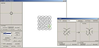
Jowers and Earl (Reference Jowers and Earl2010) describe their QI system (Jowers, Reference Jowers2006) that supports U 12 shape elements; in contrast to Trescak et al. (Reference Trescak, Esteva and Rodriguez2010), these shape elements are quadratic Bézier curves. The user interface for the QI system is illustrated in Figure 6. As with Trescak et al.'s (2010) system, both shapes and shape rules are defined using a mouse input. The implementation demonstrated at DCC'10 showed the development of a Celtic knot pattern where shape rules were used to ensure that the plaiting patterns in the generated shapes complied with the style that characterizes Celtic knots. The focus of the system is on the implementation of shape grammars that can operate on complex curves; as such integration of the system into design and product development processes is premature. In principle, however, the incorporation of a DXF-like interface, of the kind developed by Li et al. (Reference Li, Chau, Chen and Wang2009) would be feasible.
A screenshot from the QI system. Reprinted from “QI—A Shape Grammar Interpreter for Curved Shapes,” I. Jowers and C.F. Earl, 2010, Proc. 4th Int. Conf. Design Computing and Cognition. Copyright 2010. Reprinted with permission. [A color version of this figure can be viewed online at http://journals.cambridge.org/aie]

3.5. Spatial grammar implementation for machining planning
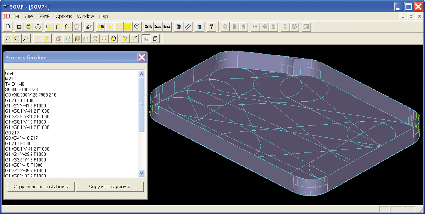
Shea et al. (Reference Shea, Ertelt, Gmeiner and Ameri2010) and Ertelt and Shea (Reference Ertelt and Shea2010) introduced the spatial grammar machining planning (SGMP) system. SGMP uses spatial grammars for the creation of a machining plan, or sequence of fabrication operations, from a given geometric model. This combination allows spatial grammars to automatically generate designs, possibly complex 3-D shapes, and also the necessary fabrication plans to produce them. In this work, knowledge of machine capabilities, specifically computer numerical control milling, has been encoded in a spatial grammar that operates on points, lines, and solids. The capabilities are represented in terms of which volumes can be removed from a work piece or unmachined material. The parametrically defined vocabulary of the grammar represents the volumes that can be removed by a machine motion and tool combination, in U 33, also including the tool path in U 13 and labeled points in U 03 for controlling the process, that is, to maintain continuity of the cutting process. Further (process) constraints are defined outside the scope of the grammar rules, for example, to avoid collisions between the cutting tool and work piece, and can be dynamically linked to rules. Further rules are developed to generate machining operations in the plan, such as repositioning of a cutting tool, that do not change the geometry of the work piece. During rule application the control code for the machine tool is instantiated, G-code, as it is defined parametrically in the vocabulary. The generation of machining plans from a given STEP-based representation of part and work piece models is implemented using a two-layer search to determine the best sequence of rules, or machining operations, and an inner loop search that finds the best parameters for a given rule application. A future step is the automated generation of the vocabulary given the available machine capabilities, such as the axes of motion, and available cutting tools, for example, with different diameters. The long-term goal is to enable a machine tool to be able to reason about its current capabilities and plan its own actions to fabricate a given, previously unknown, part. This application is unique not only for its application in manufacturing but also the “live” use of spatial grammars in a hardware-based implementation.
Like Hoisl and Shea's (2011) spatial grammar interpreter, SGMP is implemented using the open source geometric kernel OpenCASCADE. The geometric kernel is used to provide the geometric representations, in this case B-reps, and to provide the functionality to manipulate the geometric models through Boolean operations (Fig. 7).
Spatial grammar machining planning: spatial grammar to automatically generate computer numerical control machining plans for parts including executable G-code. [A color version of this figure can be viewed online at http://journals.cambridge.org/aie]

3.6. Shape grammar implementation with vision
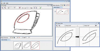
Jowers et al. (Reference Jowers, Hogg, McKay, Chau and de Pennington2010) describe the Subshape Detector 2 (SD2) system that operates on U 02 bitmaps. The focus of the system is on the integration of shape grammars into the early stages of product development processes when designers are working with hand-drawn and digital 2-D sketches. At this stage of a product development process a potential benefit of spatial grammars lies in their ability to support users in seeing and working with emergent shapes from 2-D work. The GUI for this system is illustrated in Figure 8. The system uses computer vision technology to enable the detection of given subshapes within a target shape under defined tolerances; these are needed to accommodate the reduced precision found in early design sketches when compared to more formally defined shapes such as those used in the SG development, SGI, and QI systems. Integration of the resulting design shapes into downstream applications is not addressed although is technically feasible with some human intervention using the import and trace functions of sketch-based interfaces to contemporary CAD systems such as the autotrace function in Solidworks.Footnote 2
A screenshot from the SD2 system. Reprinted from “Shape Detection With Vision: Implementing Shape Grammars in Conceptual Design,” by I. Jowers, D.C. Hogg, A. McKay, H.H. Chau, and A. de Pennington, 2010, Research in Engineering Design, 21(4), 235–247. Copyright 2010 by Springer. Reprinted with permission. [A color version of this figure can be viewed online at http://journals.cambridge.org/aie]

3.7. MALAG: A discursive grammar interpreter for the online generation of mass customized housing
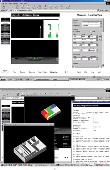
MALAG is a discursive grammar interpreter for the generation of mass customized housing online (Duarte, Reference Duarte2005). Similar to Hoisl and Shea (Reference Hoisl and Shea2011), it supports U 33 shapes but was developed for this particular application. It is composed of two modules: PROGRAMA and DESIGNA. PROGRAMA is a description grammar interpreter that produces the design brief from given user and site data (see Fig. 9a). Constraints are checked dynamically during this description process. Using this design brief, DESIGNA (see Fig. 9b), computes a set of housing designs according to a defined architectural style.
The MALAG grammar interpreter (a) as a screenshot from the PROGRAMA module and (b) as a screenshot from the DESIGNA module. [A color version of this figure can be viewed online at http://journals.cambridge.org/aie]

PROGRAMA is written in Java and deployed as an applet running in a web browser. The shape grammar rules are encoded using Jess, a rule engine for the Java platform, so that a Jess-based reasoner can be used to select and apply shape rules. The shape grammar implementation in DESIGNA is based on the work of Heisserman (Reference Heisserman1994). Its initial version used indexed lists as the data structure of the solid modeler controlled by the shape grammar rules. A new version under development (Correia et al., Reference Correia, Duarte and Leitão2010) uses Computational Geometry Algorithms Library (CGAL) that is an efficient library of data structures and algorithms for geometry-based problem solving. Given that MALAG is mainly developed in Java, CGAL's graph-based boundary representation of solids is wrapped in a Java library, thus allowing Jess rules to match and operate on CGAL's solid models, which also facilitates the implementation of various grammars. In order to visualize the generated geometries, it is planned to use HTML5 capabilities, in particular, the WebGL-capable canvas element. This will allow the user to have immediate visual feedback.
This section has introduced representative spatial grammar implementations that were presented in the DCC'10 workshop on which this paper is based. A common feature of all these systems is that they are early research prototypes; there is still a long way to go to make a significant impact on industry methods using grammar-based approaches. However, key progress illustrated includes implementations that support emergence in 2-D and those that support solids. Key aspects of “designerly” systems include integration with design and production processes, user friendly interfaces (with new methods of user interaction being explored), and representations that facilitate creation and manipulation of designs in a flexible manner suited to a designer's requirements. Finally, implementations are also now more sophisticated in terms of their software engineering basis, for example, by making use of common software libraries and integration with common CAD model data formats and tools.
4. DISCUSSION
This section builds on the discussion at the DCC'10 workshop with issues and questions arising from consideration of past and current grammar-based tools. The following questions and ongoing issues were discussed by both the authors of the systems presented in Section 3 and other participants.
1. How can we evaluate implementations of spatial grammar based tools?
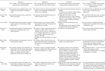
2. Can we identify a set of benchmark problems for spatial grammar implementations?
3. How can shape grammar implementations be integrated into the current software toolset (e.g., illustration and sketching software, CAD, computer-aided engineering)?
4. How might spatial grammar implementations change product development processes?
5. How can designers articulate shape grammars (i.e., vocabulary and rules) in software implementations?
Table 4 provides a summary of the presentations with respect to questions 2–5.
Summary of presentations with respect to Questions (2–4)

Note: PDP, product development process.
aAll objects in capital and small capital are identifiable.
4.1. How can we evaluate implementations of spatial grammar based tools?
The evaluation of prototype systems should reflect their reasons for being. Such systems are typically developed for one of two reasons: to demonstrate underlying theories or potential application areas. Criteria from Iordanova and Mueller (Reference Iordanova and Mueller2010) could be used to evaluate systems, as could the requirements for spatial grammar based conceptual design systems introduced in Table 2. In both cases benchmark conceptual design synthesis problems would be useful in allowing implementations to be evaluated with respect to each other.
4.2. Can we identify a set of benchmark problems for spatial grammar implementations?
Benchmark problems are needed for the two kinds of validation identified in Section 4.1: to exercise underlying theories and to demonstrate potential application areas. The latter case indicates a need for the establishment of use cases for different kinds of users doing different kinds of task; this, in turn, led to the identification of a need to understand who might use shape grammar-based systems and for what purposes. Examples of potential uses included design generation and evaluation, possibly with respect to a style, comparison of design alternatives, exploration and navigation of design spaces, and style development activities. Further, there are issues to consider concerning the support and integration of different working methods and representations between disciplines or users and design tasks, for example, industrial designers versus architects versus mechanical designers versus manufacturing engineers.
4.3. How can shape grammar implementations be integrated into the current software toolset?
A key difference between the development of solid modeling and computational design synthesis systems lies in the nature of the computational environments into which they will be incorporated. In the 1980s and 1990s, when solid modeling systems were first introduced, typical product development processes involved, if any, a small number of stand-alone packages that supported individual activities within the process. The role of the solid modeling system was seen, in this context, as being to provide product definition data as input to these stand-alone systems. This is reflected in the system architectures presented by Requicha and Voelcker (Reference Requicha and Voelcker1983) where the solid modeling system was the source of the product definition that was used, through auxiliary representations, to drive other processes, both computational and manual. In contrast, computational design synthesis systems will need to integrate with existing solid modeling systems and other applications that are nowadays routinely used within product development activities. From the systems reviewed in this paper, some progress has been made in this area. For example, Li's DXF interface allows results of a synthesis episode to be exported to solid modeling systems, Hoisl and Shea's (2011) implementation is embedded in an open-source CAD tool and Ertelt and Shea's (2010) implementation uses grammars to support the generation of manufacturing information from 3-D models represented as STEP models. A key challenge to be addressed in realizing “whole” computational design synthesis systems that could be used in real-life design processes lies in improved understanding of how such systems might be integrated with current systems, both architecturally and across software packages from both theoretical and practical perspectives. In essence, we need to revisit what Requicha and Voelcker (Reference Requicha and Voelcker1983) presented as their “contemporary congenial marriage of technologies.” The Design Compiler 43 (Alber & Rudolph, Reference Alber and Rudolph2003) is a general, Eclipse-based, platform for solving design synthesis problems based on the graph, rather than shape, grammars. However, this system provides some direction on the question of integration since its key advantage is the many interfaces provided to transform design graphs into analysis models, allowing for integration with common tools such as CAD and simulation.
4.4. How might spatial grammar implementations change product development processes?
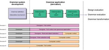
In moving forward to the realization of computational design synthesis systems that can be used by design practitioners in ways that will improve the effectiveness and efficiency of their activities, a second key area for development lies in understanding how such systems might be incorporated into design practices that already include multiple approaches and computational solutions. Given that design paradigms are unlikely to change, especially in the short term, to reflect the needs of grammar-based technologies, the first usable computational design synthesis systems will need flexible user interfaces in order that they can be tuned or adapted to suit the needs of individual designers and their design processes and practices. Chase (Reference Chase2002) identified a range of levels of automation (see Fig. 10) for the integration of shape grammar based systems with users with a focus on the capabilities of grammar-based systems. This included an architecture for user interfaces of shape grammar based design systems that divides a grammar's use into stages (development, application, evaluation) and actors (e.g., developer, user–designer) with the potential for either a human or computer to assume these roles. Appropriate user interfaces for design will also need to be focused on the needs arising from the human-driven design processes and practices rather than underlying computational design synthesis technology. In addition, they will need to support users in providing information needed to drive the system. This will include supporting the definition and development of the grammars themselves (both vocabularies and rules) and their application to design problems. Finally, achieving usable computational design synthesis systems requires attention to be directed toward system architectures so that computational design synthesis systems can be embedded in product design and development processes, both as providers of information and users of information from other systems. For example, point clouds might be used for similarity checking and the automatic derivation of new grammars that reflect the shape characteristics of groups of current designs.
The architecture for shape grammar based design systems. Adapted from “A Model for User Interaction in Grammar-Based Design Systems,” by S.C. Chase, Reference Chase2002, Automation in Construction, 11, 161–172. Copyright 2002 by Elsevier. Adapted with permission. [A color version of this figure can be viewed online at http://journals.cambridge.org/aie]

4.5. How can designers articulate shape grammars (i.e., vocabulary and rules) in software implementations?
There was general agreement that the process of defining a grammar could be used as a means of understanding a design problem but their benefits need to be made more obvious to potential users. A useful area for further development would be to think about typical learning curves for users and identify key points/stages on these curves. In addition, there is a need for more methodological support for guiding a user in the design of a grammar. For example, what constitutes a “good” rule and how might “good” rule formulation be supported?
5. CONCLUSIONS
The goal of this paper was to provide a framework for discussions around a next generation of design systems based on implementations of spatial grammars. Our discussion has touched on shape representation schemes, associated computation systems, and the product development activities (including design synthesis and fabrication) that such systems might be used within. We anticipate the role of designers and engineers changing to include the development of grammars from which shapes could be computed in generate-test cycles. System users would design, develop, and use their own grammars to generate designs in, for example, a given style or to suit the capabilities of particular fabrication process with associated constraints. Similarly, if the language of a fabrication process were captured in a grammar then it becomes feasible to automatically revise a design to suit different fabrication processes while maintaining functional requirements. In the longer term we anticipate grammar-based systems that, given a collection of designs, will be able to generate a grammar from which designs in the given set, and so a language of their designs, could be generated. In the workshop, the need to invest substantial effort to understand grammatical approaches before they can be used effectively was recognized. In particular, key aspects identified were the need for “modern” interfaces aligned with capabilities of current CAD software and the need to determine unique properties compared to say scripting and generative CAD. Current implementations have made significant progress but substantially more is needed if these aspirations are to be achieved.
The first 3-D solid modeling systems became commercially available in the early 1980s (Requicha & Voelcker, Reference Requicha and Voelcker1983). These systems were built on theoretical models established through research prototypes that emerged in the late 1970s. By the late 1990s, systems built on these models had become ubiquitous in industrial product design and development processes. If a similar path were anticipated for the development of computational design synthesis tools then, from the implementations reviewed in this paper, we are presently in a stage of computational design synthesis system development comparable to that of 3-D solid modeling systems in the late 1970s. All of the systems reviewed are demonstrable and the majority are available as downloadable software for researchers to use in design experiments. To incorporate computational design synthesis systems into product development processes on an industrial scale, two key aspects require further development: integration with existing computer-based design systems and integration into the processes of design practice. Once in use by early adopters, deeper understanding of the requirements outlined in Section 3 will be developed and so commercially viable computational design synthesis systems will emerge.
ACKNOWLEDGMENTS
This paper is based on demonstrations and discussions at a DCC'10 workshop on shape grammar implementation. The authors thank the workshop committee and participants for their contributions.
APPENDIX A
Sources and URLs of downloadable software prototypes used

Alison McKay is a Professor of design systems at the University of Leeds. Her research interests are in next-generation CAD systems; sociotechnical perspectives on new product introduction systems, including extended enterprise supply networks, through life knowledge and information management; and needs-driven product design. She was a founding member of the Leeds Socio-Technical Centre and led the development of a multidisciplinary undergraduate program in product design where she teaches design studio and design research modules. She is a chartered engineer and a Fellow of the Institution of Mechanical Engineers.
Scott Chase is a Professor with special responsibilities in digital design in the Department of Architecture, Design, and Media Technology at Aalborg University. Dr. Chase holds degrees in Architecture from MIT and UCLA. His industry employment has included Bechtel, IBM, and NIST's Manufacturing Engineering Laboratory. Previous academic appointments were in architecture and design, manufacture, and engineering management at the University of Strathclyde and the Faculty of Architecture at the University of Sydney. His research interests lie in formal generative design systems, building information modeling and virtual worlds. He is a member of eCAADe, ACM, Sigma Xi, and a Fellow of the Higher Education Academy.
Kristina Shea is a Professor for virtual product development at the Technische Universität München. She studied mechanical engineering at Carnegie Mellon University, where she completed her PhD in 1997. She has held appointments as a Postdoctoral Researcher at EPFL, Switzerland, and as a University Lecturer at Cambridge University. Her research interests are in new computational models, methods, and tools for product development with a focus on supporting early stages, design synthesis, optimization, and fabrication. Specific topics include formal, integrated product models, graph and shape grammars, multiobjective and multidisciplinary optimization and development of cognitive products, and cognitive fabrication systems.
Hau Hing Chau is a member of the Institute for Engineering Systems and Design within the School of Mechanical Engineering at the University of Leeds. He attained his PhD in 2002 from the University of Leeds on the preservation of brand identity in engineering design using a grammatical approach. Since then, his research has focused on shape computation and the implementation of 3-D shape grammar-based design systems for use in the consumer product development processes.