INRODUCTION
Flyers have been widely used by many researchers in the field of material science (Asay, Reference Asay, Trucano and Hawke1990), impact studies (Roybal et al., Reference Roybal, Stein, Miglionico and Shively1995), astrophysics (Roybal et al., Reference Roybal, Stein, Miglionico and Shively1995), condensed matter physics (Paisley et al., Reference Paisley, Warnes and Kopp1991; Swift, Reference Swift2002; Swift et al., Reference Swift, Niemczura, Paisley, Johnson, Luo and Tierney2005; Bushman et al., Reference Bushman, Kanel, Ni and Fortov1993). The areas where they have specially gained importance are: achieving sufficient velocities for compression of inertial confinement fusion target (Labaste et al., Reference Labaste, Doucet, Joubert, Schmidt and Tao1995; Decoste et al., Reference Decoste, Bodner, Ripin, Mclean, Obenschain and Armstrong1979; Krehl et al., Reference Krehl, Schwirzke and Cooper1975), ultrafast ignition of secondary explosives (Asay et al., Reference Asay, Trucano and Hawke1990; Bourne, Reference Bourne2001), measurement of equation of state (EOS) and high pressure induced phase transitions (Swift, Reference Swift2002), measurement of dynamic spall strength of various metals (O'Keefe & Skeen, Reference O'Keefe and Skeen1972; Okada et al., Reference Okada, Wakabayashi, Takenaka, Nagao, Kondo, Ono, Takamatsu, Ozaki, Nagai, Nakai, Tanaka and Yoshida2003; Robbins & Sheffield, Reference Robbins and Sheffield2000; Paisley et al., Reference Paisley, Swift, Johnson, Kopp and Kyrala2001; Wang Reference Wang2002; Watson et al., Reference Watson, Gifford and Field2000). In one of the experiments, X-ray driven flyers have been used to generate EOS data in the pressure regime of 0.75 Gbar (Cauble et al., Reference Cauble, Phillion, Hoover, Holmes, Kikenny and Lee1993). Flyers have also been used for meteorite impact studies of space micro-debris and dust on spacecraft material (Roybal et al., Reference Roybal, Stein, Miglionico and Shively1995), estimation of strength of thin films (Robbins & Sheffield Reference Robbins and Sheffield2000; Paisley et al., Reference Paisley, Swift, Johnson, Kopp and Kyrala2001; Wang, Reference Wang2002). The ability of a flyer to investigate the compressed as well as impacted material under cold conditions (without pre-heating), makes it an ideal tool for such research. Laser produced mini-flyers offers several advantages over the other techniques such as gas gun, exploding wires (Burr, Reference Burr1967; Neff et al., Reference Neff, Ford, Wright, Martinez and Plechaty2009) and chemical explosives (Swift et al., Reference Swift, Charles, Clark, Buttler, Lyon and Rightley2007) for investigating the dynamic properties of materials. In particular, the small dimensions involved (of millimeter order) and the low cost of laser shots offers advantages such as good repetition rate, reduction in experimental length and time, high shot throughput, simplified experimental apparatus and reasonably moderate energy (few hundreds of mJ) requirement to achieve flyer velocities of few km/s.
Two approach of laser based generation and acceleration of thin metallic flyers have been generally used. The first one involves direct laser irradiation of thin metallic foils. In this method, a high power pulsed laser beam is focused at high intensity on a solid target. The plasma created at the surface liberates and accelerates the rear target to velocities up to few km/s by the process of ablative acceleration (Decoste et al., Reference Decoste, Bodner, Ripin, Mclean, Obenschain and Armstrong1979; Ripin et al., Reference Ripin, Decoste, Obenschain, Bodner, Mclean, Young, Whitlock, Armstrong, Grun, Stamper, Gold, Nagel, Lehmberg and Mcmohan1980). Research on ablative acceleration of thin foil targets by intense pulsed lasers began in 1970's. Since then several researchers have utilized this technique to study various phenomenon associated with laser matter interaction. Velocities as high as 13 km/s have been achieved by the direct laser irradiation method (Tanaka et al., Reference Tanaka, Hara, Ozaki, Sasatani, Kondo, Nakano, Nishihara, Takenaka, Yoshida and Mima2000). Though direct laser irradiation of targets have been used to achieve high flyer velocities (tens of km/s), it has some limitations. For example, the preheating of the target rear surface due to the thermal heat transport vaporizes the material of the flyer. The second method involves indirect laser irradiation of thin metallic targets attached to an optically transparent substrate (Greenway et al., Reference Greenway, Proud, Field and Goveas2003; Paisley, Reference Paisley1991). In this method, a moderate power laser pulse is focused at the substrate-target interface through transparent side. The plasma created at the interface is confined by the massive substrate (providing the necessary tamping effect) that liberates the target by stress induced spallation (Paisley, Reference Paisley1991; Setchell et al., Reference Setchell, Trott, Farnsworth, Casteneda and Berry2002). The advantage of this method over the direct laser irradiation is that velocities as high as km/s can be achieved using a moderate power laser that is limited by the damage threshold of the substrate material. Use of multi-layered targets involving efficient laser energy absorbing material and thermal insulator material helps in minimizing the heat transport to the rear of the target, thus allowing flyers to be accelerated in solid from in both direct (Tanaka et al., Reference Tanaka, Hara, Ozaki, Sasatani, Kondo, Nakano, Nishihara, Takenaka, Yoshida and Mima2000) and indirect drive methods (Miller et al., Reference Miller, Kishimura, Kelly and Thadhani2009; Watson et al., Reference Watson, Gifford and Field2000). Another advantage of indirect method is that the laser beam doesn't require to be tightly focused. A few mm spot size focusing is sufficient (as compared to about 100 µm in direct drive method) to achieve high velocities.
A Gaussian laser beam profile irradiates the target surface non-uniformly. This results in non-uniform acceleration of material with peak at the center of the target. Another phenomenon that is common to non-uniform laser energy deposition is the hot spot generation in the plasma. This leads to pre-heating of the target material before it is compressed and launched resulting in fast vaporizing of the material (Honrubia et al., Reference Honrubia, Dezulian, Batani, Bossi, Koenig, Benuzzi and Grandjouan1998). The requirement of beam smoothing for planar shock generation and uniform illumination of inertial confinement fusion targets has made this subject extensively studied. Many techniques have been reported for laser beam smoothing such as random phase plate (RPP) and phased zone-plate (PZP) (Batani et al., Reference Batani, Bleu and Löwer2002; Bennuzi et al., Reference Benuzzi, Koenig, Faral, Krishnan, Pisani, Batani, Bossi, Beretta, Hall, Ellwi, Hüller, Honrubia and Grandjouan1998; Dixit et al., Reference Dixit, Thomas, Rushford and Merril1994; Kato et al., Reference Kato, Mima, Miyanaga, Arinaga, Kitagawa, Nakatsuka and Yamanaka1984; Koenig et al., Reference Koenig, Faral, Boudenne, Batani, Benuzzi and Bossi1994; Lehmberg & Obenschain, Reference Lehmberg and Obenschain1983; Skupsky et al., Reference Sckupsky, Short, Kessler, Craxton, Letzring and Soures1989; Stevenson et al., Reference Stevenson, Norman, Bett, Pepler, Danson and Ross1994), multiple lens array (Deng et al., Reference Deng, Liang, Chen, Yu and Ma1986), diffuser (such as ground glass or integrating sphere) and optical fiber (Greenway et al., Reference Greenway, Proud, Field and Goveas2003). Each method has some advantages over other. The phase modulators (such as RPP or RPZ), which converts the coherent wave to random-phased wave, has to be kept very close to the target that makes conducting experiment inconvenient. Moreover, theses plates are expensive too. The multiple lens array assembly requires precise lenses with high numerical aperture and low aberration to be fabricated, which makes it difficult to design. In the case of speckle pattern generated by ground glass, reflections from a rough surface of glass are the combination of both scattering and interference phenomena. As surface roughness increases, the scattering effect plays a dominant role that reduces the laser beam intensity. Also, there is no precise control on the speckle generation. Integrating sphere involves the multiple diffuse reflections of laser in it and produces speckle pattern for modulation transfer function testing of detectors. Step index multimode optical fiber has also been used by many researchers (Greenway et al., Reference Greenway, Proud, Field and Goveas2003; Paisley, Reference Paisley1991) for laser beam smoothing. Incident laser beam propagating through such a fiber excites many optical modes travelling at different velocities. However, the small random fluctuations in the core radius or the refractive index affect the propagation by introducing random phases into the modes. As a consequence the optical modes interfere at the output of the fiber and their overlap produces a speckle pattern. This profile has fine-scale intensity variations (“modal noise”) due to interference between propagating fiber modes, with the amplitude of these variations dependent on the temporal coherence of the laser. Inside a multimode fiber, the optical radiation is distributed between all the possible propagation modes thus acting to smooth out “hot spots” and non-uniform features within the beam profile.
In this paper, we present generation of planar mini-flyer generation using a fiber optic plate for laser beam smoothing. This technique is unique in the sense that it doesn't require large length as compared to the optical fiber (few tens of meters). A fiber optic plate is a bundle of fibers with individual fiber dimension of few microns and overall length of a few mm. The diffraction pattern from each fiber overlaps to from a smooth laser beam profile (both in near and far field patterns). We have used this technique to produce planar mini-flyers of materials such as Al, Cu, Br, and Ta. A solid state Nd:Glass laser with energy about 300 mJ to 400 mJ and duration 2 ns was used as a driver. The laser was focused to a spot size of about 1.5 mm on the target kept in air to achieve flyer velocities of about 0.4 km/s. Accelerated flyers were recovered in solid form after the laser shot. Laser beam profile smoothing achieved using FOP has been compared with the theoretical modeling. Diffraction theory for overlapping beamlets emerging out of the FOP was used to model the laser smoothing. The results corroborates well both experimentally and theoretically.
EXPERIMENT
Laser Beam Smoothing Study Using 2 mw He-Ne Laser
When coherent pulse propagates through a random media, the scattered waves interfere randomly to give a fine, peculiar, high-contrast, granular virtual objective pattern called “Speckle.” It exhibits an interference image that contains lots of information about the characteristics of the illuminated scattering object and the process being analyzed. Being optical non-contact pattern the important aspects of speckles are determining the activity quantity from the materials under study (Braga et al., Reference Braga, Nobre, Costa, Safadi and Costa Da2011). The time varying speckle pattern also plays an important role in many physical phenomena like in measurement of dynamic object (Semenov et al., Reference Semenov, Sidorov, Nippolainen and Kamshilin2010), metrological and stress corrosion analysis (Chiang & Kin, Reference Chiang and Kin1982; Lu & Zou, Reference Lu and Zou2010), surface deformation and roughness measurement (Ling et al., Reference Ling, Zhao and Pon1986), bio-speckle study in seed analysis (Nobre et al., Reference Nobre, Braga, Costa, Cardoso, Dasilva and Sáfadi2009) besides smoothing of the laser beam (Veron et al., Reference Veron, Ayral, Gouedard, Husson, Lauriou, Martin, Meyer, Rostaing and Sauteret1988).
In an optical fiber, the number of speckle spots is given by the number of modes of the fiber and is limited by the acceptable angular spread of the beam, while the time delay is proportional to the length of the fiber (Garnier & Videau, Reference Garnier and Videau1997). The length of the optical fiber is chosen such that it generates number of independent interference patterns simultaneously superimposed on the target resulting in a smooth laser beam profile. To achieve this the laser pulse duration should be considerably larger than the coherence time and the light ray should be delayed as per the equation (Veron et al., Reference Veron, Ayral, Gouedard, Husson, Lauriou, Martin, Meyer, Rostaing and Sauteret1988),
 $$\Delta t = \displaystyle{{L\theta ^2 } \over {2nc}}.$$
Where L is the length of the optical fiber, n is the refractive index, θ is the angle of incidence in radians. Thus to obtain a delay of 1 ns for n = 1.5 and θ = 0.12 radian the length of optical fiber required is 50 m.
We have used a FOP plate to produce a flat intensity laser profile. The main advantage of this technique is that it doesn't require large length as compared to optical fiber. To achieve a reasonable flat profile, the FOP should have some degree of randomness either in individual fiber length or in diameter. This has been explained by the diffraction analysis of both ordered and random FOP's as explained in the next section to understand their operation for a Gaussian beam.
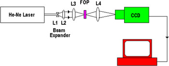
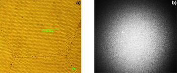
Figure 1 shows the experimental setup used for laser generated speckle analysis using fiber optic plate. The study of laser beam smoothing using FOP was carried out with 630 nm He-Ne laser (instead of 1064 nm) so as to avoid the damage of CCD camera chip. An expanded beam was used that exactly matched the laser beam size at 1064 nm used for mini-flyer generation. The beam was expanded to about 20 mm and then focused at spot size of about 1.3 mm with the help of lens L 3 (f = 50 mm) on a FOP. We have used two types of FOP's to study the laser beam smoothing. Figure 2a shows the photograph of the FOP of 25 mm diameter and thickness 8 mm taken using high resolution optical microscope. The individual fiber dimension was found to be about 6 µm. The output from the rear end of the FOP was collected using lens L 4 (f = 30 mm) and imaged on the chip of a high resolution CCD camera. Figure 2b shows the recorded speckle pattern using lens L 4 and a high resolution monochrome CCD camera. This FOP was designated as random FOP as it generated speckle pattern that corroborates well with the diffraction analysis for the random plate as presented in the next section.
(Color online) Schematic of experimental setup for laser generated speckle using He-Ne laser and FOP.

(Color online) Random FOP (a) microscopic image, (b) corresponding diffraction pattern.

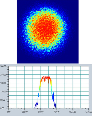
Lens L 4 was adjusted to obtain the expanded (speckle) as well as focused intensity pattern. Figure 3 shows the recorded intensity profile of the speckle pattern at the focal plane using the experimental setup of Figure 1. The flatness of the profile can be clearly seen. The high frequency ripples at the flattop has reduced sensitivity for laser produced plasma at 1064 nm at the focal plane. Besides this lateral energy transport due to thermal conduction also helps in mitigating the effect caused by these ripples.
(Color online) Focused speckle pattern and intensity profile.

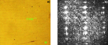
Figure 4 shows the microscope image and the pattern recorded for second type of FOP with 25 mm diameter and individual fiber dimensions of about 6 µm. This plate was designated as ordered FOP as it generated pattern that corroborates well with the ordered diffraction pattern through a bunch of optical fibers. The analysis of this is also presented in the next section. At the focal plane of the lens L 4 (Fig. 1), multiple spots were obtained.
(Color online) Ordered FOP (a) microscopic image, (b) corresponding diffraction pattern.

Planar Mini-flyer Generation Using FOP Laser Smoothing Technique
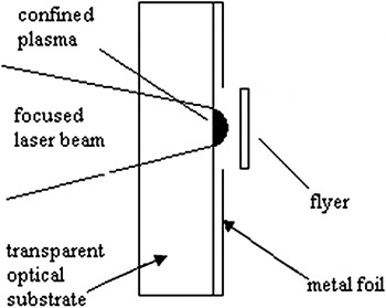
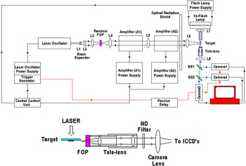
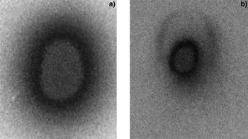
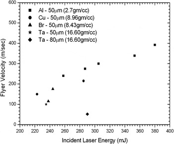
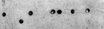
The final laser smoothing was done for 1064 nm Nd:Glass laser using the FOP technique described above. The technique was employed for generating planar thin mini-flyer generation. For this purpose, driven indirect drive approach was adopted as shown in Figure 5. The target for this approach consisted of thin metal flyer disks (diameter 5mm and thickness 50–80 µm of different materials such as Al, Br, Cu, and Ta) attached to the optical substrate (fused silica). A moderate power laser pulse (up to about 400 mJ) was focused at the substrate-target interface through transparent substrate side. The plasma created at the interface was confined by the massive substrate and provides the necessary tamping effect. The stress wave generated exerts pressure on the un-vaporized material and ejects it in the form of flyer due to spallation (Lehmberg & Obenschain, Reference Lehmberg and Obenschain1983). Figure 6 shows the schematic diagram of experimental setup. It consists of a Q switched Nd:YAG laser oscillator capable of delivering laser pulse of energy 150 mJ and duration 2 ns. This oscillator was a part of the 2 J laser chain consisting of beam expander, two 25 mm diameter silicate Nd:Glass laser amplifiers in double pass configuration, Faraday isolator. The laser chain was modified by introducing the random FOP with lenses L 3, L 4, and L 5 as shown in Figure 6. Lens L 3 was used to obtain a focal spot of about 1.3 mm diameter at the input of the FOP. The speckle pattern generated at the exit of FOP was relayed using lenses L 4 and L 5 through the two amplifiers as shown in Figure 6. Amplified beam was finally focused to a spot size of about 1.3 mm at the substrate based target interface using lens L 6. The energy was measured to be about 400 mJ. Figure 7 shows the burn pattern of the beam just after the amplifiers and at the focal plane of lens L 6, respectively. Three ICCD high speed framing cameras were used to record the flyer motion. These cameras were capable of recording minimum frame duration of 200 ps. A xenon flash lamp driven by high voltage capacitive discharge power supply was used as a back lighting source. Target image was split into three parts using beam splitter before imaging on the ICCD cameras as shown in Figure 6. It was imaged on the photocathodes of the cameras with the help of tele-magnifying lens system assembly consisting of a fiber plate, tele-lenses, and camera lenses. Multi-layered substrate based targets were used to study the flyer motion. We had used fused silica optical substrate of dimension 65 mm (Length) × 5 mm (Width) × 1 mm (Thick) on which thin metal disks (Al, Cu. Br, or Ta) of diameter 1.5 mm were fixed using epoxy glue suitably diluted in acetone. These flyer disks were glued on the substrate pre-deposited with thin layer of carbon (3 µm) and alumina (Al2O3 – 5 µm). These layers were deposited using DC RF sputtering technique. Carbon was deposited to increase the laser absorption whereas alumina layer helped in providing heat shield to the flyer disks from the plasma due to its low thermal conducting properties. Figure 8 shows the recorded image of the recorded frames of the motion of planar mini-flyer made of 50 µm alumina circular disk (1.5 mm diameter) at different times. These times were set by adjusting the ICCD's trigger delay. The images were recorded for frame duration of 5 ns. Planar flyer motion in solid form is clearly visible from these snap shots. The flyer disks were completely recovered in intact form after the laser shot. Maximum velocity of the flyer was measured to be about 400 m/s for alumina. Similar frames were recorded for different flyers made of Cu, Br, and Ta. Measured velocities for different targets are represented in Figure 9 and the recovered flyer disks after the shot is shown in Figure 10.
Substrate based laser driven mini-flyer using indirect drive approach.

(Color online) Experimental setup for indirect drive scheme for planar mini flyer generation and tele-magnifying lens arrangement.

(a) Beam after the amplifiers. (b) Beam after the focusing lens L 6.

Frame shots of planar mini-flyer launch made of 50 µm Al using laser smoothing by random FOP at incident laser energy of about 300 mJ.

Measured Flyer velocity as a function of laser energy.

Recovered flyer disks after the shot with smooth laser beam profile using FOP.

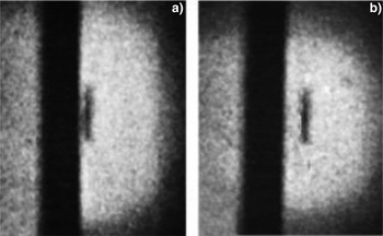
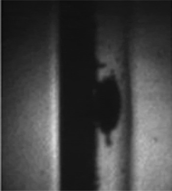
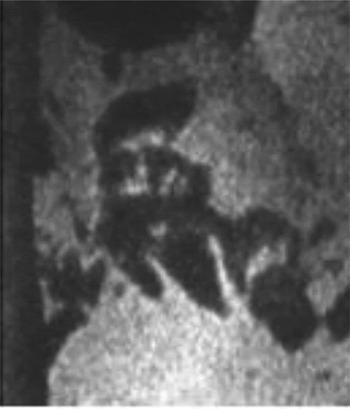
The experiment was also performed with Gaussian laser beam profile without FOP. Figure 11 shows the recorded images of alumina flyer disk of diameter 1.5 mm and thickness 50 µm at incident laser energy of about 300 mJ. It can be seen that the flyer plate emerges from the substrate in intact form. It follows the laser beam profile with some vaporized material behind it. However, the motion of the flyer is not uniform with peak motion at the center than at wings. After laser shot, flyer plate was not recovered. This infers that excess heat is transported to the other side of the foil during motion that completely vaporizes the material. In one of the shots at laser energy about 500 mJ the flyer plate was observed to be shattered with the fragments going in all the directions as shown in Figure 12.
Image of flyer motion for Gaussian beam laser profile at incident laser energy of about 300 mJ.

Image of shattered flyer material for Gaussian beam laser profile at incident laser energy of about 500 mJ.

Theoretical Analysis of Laser Beam Smoothing Using FOP
An optical fiber (of diameter d) acts as a single mode optical fiber if its diameter is on the order of the wavelength (λ) of the incoming light. For a bunch of optical fibers (FOP) each individual channel generates a diverging source with natural divergence given by λ/d. This divides the incoming beam into many beamlets which, when allowed to propagate through space interfere with each other and generate a diffraction pattern. If the phases of individual beamlets generated by the given fiber optic plate are not synchronized, the random phase difference between them causes to make a diffraction pattern, which is the desired speckle pattern. The diverging speckle pattern when focused using a lens gives a smooth laser profile at the focal plane of a lens.
To study the feasibility of the concept, the process of speckle formation was simulated using a source TEM00 mode of Gaussian beam with wavelength 630 nm of He-Ne laser beam. Ray optics was applied for the propagation of the beam through the fibers while diffraction theory has been used for its further propagation in space.
Let us consider a wave-front of the incident beam with amplitude A in (x, y) and phase distribution e iφ(x,y) given by,
 $$F_{in} \left({x\comma \; y} \right)= A_{in} \left({x\comma \; y} \right)\; e^{i\varphi \left({x\comma y} \right)}.$$
When this wave-front passes through the bunch of fibers (FOP), then due to multiple interactions (refraction and reflection) the amplitude and phase get modified. This modification of incident beam is characterized by optical transfer function of the fiber optic plate.
The single mode fiber optic plate considered for this study has been modeled with a two dimensional distribution (optical transfer function) is given by,
 $${\rm O}_{\rm T} \left({X^{\prime} \comma \;Y^{\prime}} \right)= {\rm M}_{\rm T} \; \left({X\comma \;Y} \right)\; e^{i\varphi _T \left({x\comma y} \right)}.$$
Where, M T (X, Y) characterizes the modification in the amplitude and and φT (x, y) characterizes the modification in the phase of the incident wave front.
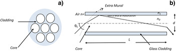
Modification in the amplitude of the beam depends only upon the structure of the fiber optic plate and distribution of individual fiber in it. We have model it with a matrix possessing the region of beam transmission with a value one and rest of the region with a value zero (Figure 13a). The modification in phase of the incident beam depends upon number of reflection and refraction of wave in the individual fiber which consequently depends upon several parameters like incidence angle-θ, length-L and diameter of the fiber-d (Fig. 13b). Thus the distance between any two reflection points would be d/tanθ. So the number of times a ray undergoes reflection Ltanθ/d. As each reflection would change the phase of wave by π rad, hence change in the phase of wave due to reflection can be modeled by equation π(Ltanθ/d). Similarly path length travelled by ray between entry and exit of the waveguide is L/cosθ, where L is the total length of fibre. If L 0 is the mean length of the fibers then the phase difference between the rays can be modeled as 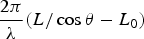 $\displaystyle{{2\pi } \over \lambda }\lpar L/\cos \theta - L_0 \rpar $ where λ is the wavelength of the incident light. Thus total phase part of the optical transfer function can modeled according to following equation,
 $$\varphi _T \lpar x\comma \; y\rpar = [ \pi\lpar L \tan {\theta/d}\rpar \rsqb \quad \rm {due\, to\, diameter\comma \; }$$
 $$=\left[\displaystyle{{2\pi } \over \lambda} \lpar L / {\cos \theta }- L_0\rpar \right]\quad \rm {due\, to\, length.}$$
(Color online) (a) Multi-fiber construction with core transmission taken as 1 and cladding transmission taken as zero. (b) Beam propagation through an optical fiber. L = length of the fiber, d = diameter of fiber core. θC = acceptance angle.

After modification due to its passage through FOP the wave-front at exit of FOP is given by the product of incident wave front and the optical transfer function of FOP which is
 $$F_{\rm {out}} {\lpar x^{\prime}\comma \; y^{\prime}\rpar } = A_{in}\lpar x\comma \; y\rpar e^{i\varphi \lpar x\comma y\rpar } O_{\rm T} \lpar X^{\prime}\comma \; Y^{\prime}\rpar.$$
As this modified beam propagates through the space, it generates diffractions pattern due to the mutual interference of the beam at various distances from FOP depending upon the fulfillment of the required criteria of the diffraction. The overall result of this interaction is each individual fiber acts as a diverging source with natural divergence λ/d. If d 2/λz~1, the diffraction pattern obtained is said to be near field diffraction (Fresnel diffraction) while if d 2/λz < 1, the diffraction pattern obtained is said to be far field diffraction (Fraunhoffer diffraction). The problem was investigated for both near (Fresnel) and far (Fraunhoffer) region of diffraction.
For Fresnel diffraction region, the diffraction pattern is obtained by multiplying the beam wave function by Fresnel propagator and the propagated wave-front is given by,
 $$Q_{Fres} \lpar x\comma \; y\rpar = c\int\!\!\!\int {F_{out} } \lpar x^{\prime}\comma \; y^{\prime}\rpar e^{ - 2\pi i \left[\lpar x - x^{\prime}\rpar ^2 +\lpar y - y^{\prime}\rpar ^2 /\lambda z \right]} dx^{\prime}dy^{\prime}.$$
The intensity distribution at the image plane is given by
 $${\rm I}_{\rm o} =\vert { Q_{Fres}\lpar x\comma \; y\rpar }\vert ^2.$$
With z as a propagation distance and x and y are the co-ordinates of image plane. In Fraunhoffer diffraction region (d 2/λz < 1), the diffraction pattern is given by,
 $${\rm I}_0 =\vert { Q_{Fraun}\lpar l\comma \; m\rpar }\vert ^2\comma$$
 $$Q_{Fraun}\lpar l\comma \; m\rpar ={\int\!\!\!\int }\;F_{out} \lpar x\comma \; y\rpar e^{2\pi ik[ \lpar lx + my\rpar \rsqb } dx\, dy.$$
Eq. (8) indicates clearly that both Fraunhoffer diffraction pattern is nothing but the Fourier transform of beam wave function at the exit plane of the FOP.
Both near field and far field cases were analyzed using the code. However, we present here the simulation results of Fraunhoffer (far field) region only since the experiment was performed in the far field geometry. This is the limitations because, for experimental fulfillment of the condition in near field, the detector has to be kept in impossibly close proximity with the FOP.
The function O T (x, y) in Eq. (3) is not always an ordered function of (x, y) but can also be a random function. This is possible because of small randomness in the arrangement of fibers or due to the variation in length and diameter that may cause a random modification in the incident beam. Depending upon the available fiber optic plate there is a possibility of randomness in M T (x, y) due to randomness in interspacing between individual fibers or in φT (x, y) due to randomness in length, diameter of fiber or in both.
To study this effect the simulations were carried out for following cases:
a. FOP with equal diameter and length of all individual fibers (No randomness),
b. FOP with randomness in length and diameter of individual fibers (Randomness in the Phase part of the optical transfer function).
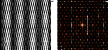
The optical transfer function of a FOP ordered in amplitude as well as in phase is shown in Figure 14a. For such FOP's, the diverging beamlets coming out of FOP interfere to make a regular diffraction pattern, i.e., normal N slit diffraction pattern as shown in the simulated pattern in Figure 14b. This pattern corroborates well with the pattern obtained experimentally for the ordered FOP as shown in Figure 4.
(Color online) (a) Simulated optical transfer function of an ordered FOP. (b) Corresponding diffraction pattern.

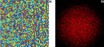
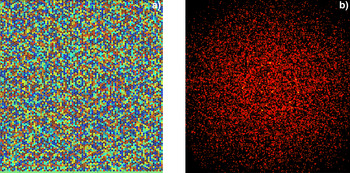
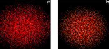
Phase part of optical transfer function of FOP is possible to be random because of two reasons — the randomness of length or the randomness of diameters of various fibers. To study the effect of their individual contribution in the randomness of the optical transfer function, the two cases has been studied separately. Figure 15a shows the optical transfer function with randomness in the length (0.008%) of the fibers of equal diameters. The scale of the figure varies from –π to +π, which is the range of phase changes introduced in the various portions of the incident wave-front over the FOP. Corresponding diffraction pattern for this case is shown in Figure 15b. Similarly, Figure 16a shows the optical transfer function with randomness in diameter (15%) of the fibers of equal length. The corresponding diffraction pattern is shown in Figure 16b.
(Color online) (a) Optical transfer function due to 0.008% randomness introduced in length. (b) Corresponding diffraction pattern.

(Color online) (a) Optical transfer function due to 15% randomness introduced in diameter. (b) Corresponding diffraction pattern.

Various values of randomness were introduced in above studied cases (Fig. 17) and it was observed that there exists a minimum required randomness to achieve the required speckle pattern. If the randomness introduced was lesser than this value then a certain ordered structure was found. The quantification of this randomness in under study and will be presented separately. For the present case it was found that to achieve a complete speckle pattern a minimum randomness on the order of 0.0008% in the length of fibers or 3% in diameter of fibers is required.
(Color online) Simulated results of speckle for randomeness (a) 0.006% in length & 3% in diameter of individual fibers, (b) 0.006% in length and 5% in diameter of individual fibers.

These simulation results show that it is possible to generate a speckle pattern if there is randomness in length and diameter of the fibers. The randomness in the FOP plate used for the experiment could not be measured due to experimental limitation. However, it is predicted that the FOP used for generating smooth laser profile has some randomness either in length or in diameter or in both. The experimental results corroborates well with the theoretical results. As the experiment was performed specially in the context of generating incoherent flattop smooth laser profile for uniform illumination of target, the effect on pulse duration is the prime issue. In a long length (>10 km) single mode optical fiber transmission, the pulse broadening has been observed due to the group velocity dispersion (GVD) (Kawana et al., Reference Kawana, Kawachi, Miyashita, Saruwatari, Asatani, Yamada and Oe1978; Nakatsuka & Grischkowsky, Reference Nakatsuka and Grischkowsky1981). However, since the length of each fiber of FOB plate used in this study was only 8 mm (where GVD is negligible), no change in the pulse width is predicted. The main phenomenon is controlled by the diffraction generated speckle pattern.
CONCLUSION
To conclude, it can be said that planar mini-flyers of different materials such as Al, Cu, Br, and Ta were produced using FOP based laser smoothing technique. The technique is unique in the sense that it doesn't require long length optical fiber (about tens of meters). Instead a FOP plate (~8 mm in thickness) with some randomness in length or/and in diameter of the individual fibers can be used for generation of planar mini-flyers. A moderate energy (few hundred mJ) solid state laser is required for achieving flyer velocities of km/s in substrate based targets on which flyer disks are attached. However, velocities ranging from 50m/s to about 400 m/s were achieved for different materials in the present experiment described. A multilayered target geometry on an optical substrate consisting of Carbon layer (few microns) followed by alumina layer (few microns) has helped in increasing the laser energy absorption and providing thermal barrier to the flyer material. However, the laser energy coupling can further be increased by using anti-reflection coatings on the optical substrate. For the present case, no anti-reflection coating was done on the fused silica optical substrate. The results corroborates well with theoretically simulated results using the diffraction theory for laser light interacting with a bunch of optical fibers, i.e., a FOP. The efficiency of the FOP can be increased by use of proper FOP material which has high laser transmission. Anti-reflection coating at the both input and output face of the FOP can further add up to efficiency.
ACKNOWLEDGEMENT
We would like to thank Dr. H.S. Vora, RRCAT, Indore, India for providing the image processing software PROMISE for this study.