Introduction
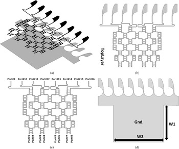
Beam-switching antennas have been a prominent research topic for studying in telecommunication and wireless systems. The consequences of multi-pass fading and interference, and polarization mismatch are an inherent restriction on the system's performance. A suitable antenna design with controllable and narrow beams solves the above failures. Polarization effect for microwave applications is vital, and polarization inconformity decreases the signal amplitude more than 30 dB. The reflection effect in multi-pass and polarization mismatch leads to the conversion of right-handed circular polarization (RHCP) to left-handed circular polarization (LHCP) and vice versa. RHCP to LHCP conversion can be neglected if both the transmitter and receiver antennas profit from circular polarization (CP). CP property can be achieved with different techniques. Some of the methods that are utilized to excite two orthogonal modes have been investigated as: (1) inserting a T-shaped grounded strip which is perpendicular to CPW feed line; (2) etching two inverted L-shaped grounded strip around two opposite corners of the slot antennas; (3) inserting spiral slot in ground plane. Gain improvement is the main challenge in X-band antennas [Reference Sedghi, Aribi and Kalami1–Reference Sedghi4]. Although increasing antenna aperture size is a proposed method in literatures to enhance the antennas’ gain, the downside is decreased coverage areas and bandwidth [Reference Sedghi4–Reference Shafei and Sedghichongaraluye-yekan10]. To overcome the above-mentioned problems, beam-steering feed network is used with antennas which are capable to support high gain and CP property over the wide range is a good candidate [Reference Sedghi, Shafei, Kalami and Aribi11–Reference Rafiei, Sharifi, Karamzadeh and Kartal19]. Among different types of beam-switching feed networks, Butler matrix with mild intricacy and best performance is a prominent choice. Butler matrix is widely utilized in switched beam systems due to its simple realization. This geometry interests from a low number of microwave components (for instance crossovers and hybrid couplers) that have drawn many researchers in recent years [Reference Sharifi, Zehforoosh, Sedghi and Takrimi9–Reference Chauhan, Rajput and Mukherjee18]. Utilizing micro strip feed delay-lines in microwave frequencies (such as X-band) and high-power applications have intragenic limitations. In this manuscript, 8×8 circularly polarized butler Vivaldi switched beam antenna array fed by 8 × 8 butler matrix is introduced (see Fig. 1). The proposed array is made of Vivaldi radiating element that has a broadband specification along with stable patterns for X-band. Moreover, using microwave components leads to intended phase differences at the output ports, which excite the two orthogonal modes and CP property is achieved. Extracted results illustrate that the realized antenna has an impedance-matching bandwidth of 5.7 GHz that extends between 7 and 12.7 GHz, and 3 dB an axial-ratio bandwidth of 3.15 GHz between 8.15 and 11.3 GHz. Gain value is more than 17 dBi at X-band.
Configuration of presented antenna array: (a) 3D view, (b) top layer, (c) feeding network, (d) bottom layer.

Antenna design methodology
In order to design the desired antenna, three main goals are considered. In the first step, in order to cover the X-band, the Vivaldi element, considering that the antipodal Vivaldi antennas (AVAs) do not have wide lateral sizes and easy to manufacture. These antennas have been utilized in several broadband applications, such as indoor localization systems and see-through-wall imaging. However, their overall characteristics are generally prohibited by the demand for a broadband feeding network. AVA has a broadband specification along with directive stable patterns at operational bandwidth.
In the next step, the broadband feeding network is designed to excite AVAs. Double-box elements are used in the topology of feeding network to improve bandwidth.
In the last step, by using the output couplers and selecting the appropriate length of the microstrip lines to feed the elements, the CP and beam-switching property is obtained. All the designed parameters are calculated for the center frequency of X-band (10 GHz).
Vivaldi element design
The modified scheme of single-feed Vivaldi element is shown in Fig. 2. The simulated response for reflection coefficient along with gain value is shown in this figure. It is clear that the impedance bandwidth is between 8.7 and 11.2 GHz (~33%) and the average gain value at operation band is approximately 6.2 dBi. The total size of Vivaldi element is 24 × 45 × 0.8 mm3 which has been printed on Rogers RO4003 dielectric substrate with a relative permittivity of 3.55 and a loss tangent of 0.002. Element dimensions are as follows (units: mm):

Geometry of array element with impedance bandwidths and gain.

Feed network
Switched beam feeding network of the presented array is made of eight inputs, eight outputs, 12 double-box broadband hybrid couplers, 10 crossovers, 12 half-crossovers, and 50Ω microstrip lines, as shown in Fig. 3. Crossover is used to isolate microstrip lines in the layout. The structure of feeding network is planned in a way that the mutual coupling was minimal. This geometry can help to improve the accuracy of beam forming in X-band. Crossovers and half-crossovers are used that help to achieve signals with approximately equal amplitudes at output ports for excitation of radiating elements. The distance among two adjacent radiating elements is 0.5λ at 10 GHz, where λ is free space wavelength. Design and optimization process of presented network is done by Agilent advanced design system commercial software. The diagrams of transmission and reflection coefficients for two ports (ports 1 and 2) excitation are depicted in Fig. 4. It clear that, the curves have agreeable operation at operational X-band.
Geometry of feeding network.

Simulated results of feeding network. (a) Transmission and reflection coefficients when port 1 is fed. (b) Transmission and reflection coefficients when port 2 is fed.

Extracted results
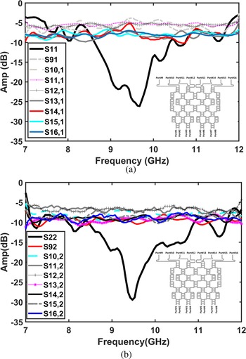
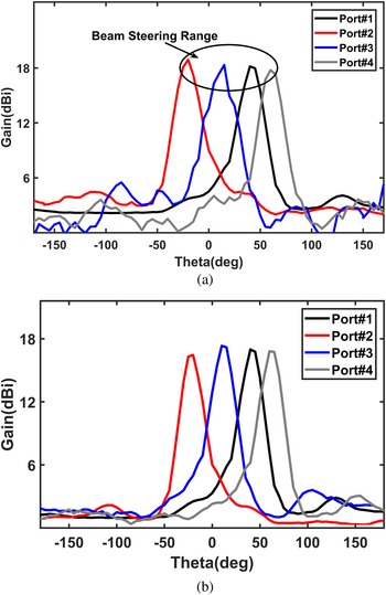
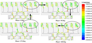
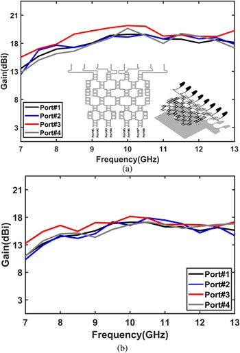
The presented Vivaldi beam-steering antenna was fabricated and simulated to affirm the designs. Due to the symmetrical structure of the array, only four ports were analyzed. The scattering parameters have been extracted by Agilent 8722ES vector network analyzer along with KeySight (NPA-X 26 GHz). Figure 5 illustrates the simulated results of return loss for antennas when ports 1 and 4 are fed. The impedance bandwidth is between 7.2 and 12.2 GHz for port 1 (~55%) and 6.9 and 13 GHz (~59%) for port 4. Figure 6 also shows this parameter for ports 2 and 3. The impedance-matching bandwidth is 6.8–12.2 GHz (~52%) and 7.5–12.3 GHz (~51%) for ports 2 and 3, respectively. Due to the fact that the design goal is to access operational X-band, all of the four ports will be able to cover this band. Figure 7 depicts the extracted results of axial ratio for the above-mentioned four ports excitation. The axial-ratio bandwidth is from 8.15 to 11.4 GHz for port 1 (~34%), 8.4 to 11.3 GHz for port 2 (~30%), 8.4 to 11.6 GHz for port 3 (~32%), and 8.15 to 11.3 GHz for port 4 (~33%). It is noteworthy that due to the structure of the feeding network, CP is achieved in more than 80% of the operational band. As mentioned earlier, only four ports were measured due to array symmetry. The measured return-loss curves of ports 1 and 4 are depicted in Figs 8 and 9. Figure 8 exhibits that the impedance bandwidths of the array are from 7 to 12 GHz (~52%) for port 1 and 7 to 12.7 GHz (~58%) for port 4 excitation. The values for ports 2 and 3 stimulus are among 7–11.9 GHz (~52%) and 7.4–12.5 GHz (~53%) for both ports respectively. Extracted patterns at 10 GHz are plotted in Fig. 10. It is clear that the patterns have a directive main lobe with an acceptable value for X-band application. Main beam directions are at θ = 48°, θ = −42°, θ = 17°, and θ = 55° for ports 1, 2, 3, and 4, respectively. The radiation patterns of the proposed antenna can cover a beam-steering angle of about −42° to 55°. Figure 11 illustrates the axial ratio of the presented array as a function of elevation angle for ports 1 and 2 at 10 GHz. It is obvious that the main lobe of antenna has CP property at two ports excitation. Figure 12 shows E-field rotation at different phases. It is found that in the desired time and phase intervals, the E-field vector rotates in a clockwise direction that proves CP feature. Figure 13 shows the measured gain of antenna arrays for four ports excitation. The maximum gain value is about 18 dBi. It is better to mention that the average gain value exceeded from 17 dBi for all ports at implicational X-band.
Simulated results of return loss for antenna when ports 1 and 4 are fed.

Simulated results of return loss for antenna when ports 2 and 3 are fed.

Extracted results of axial ratio for ports 1, 2, 3, and 4 excitation.

Measured results of scattering parameters for ports 1 and 4 excitation.

Measured results of scattering parameters for ports 2 and 3 excitation.

Extracted rectangular radiation characteristics of gain when ports 1, 2, 3, and 4 are fed; (a) simulation, (b) measured.

Extracted axial ratio versus θ variation when two ports are fed at 10 GHz.

E-field variation when port 1 is fed at 10 GHz.

Extracted gains of antenna versus of frequency when four ports are fed; (a) simulation, (b) measured.

Conclusion
Switched beam butler Vivaldi antenna array with enhanced impedance matching, gain value, and CP is presented. Vivaldi radiating element is used because of its unique features such as broadband impedance matching and relatively high gain. The antenna array consists of eight Vivaldi elements with a 1 × 8 platform and an 8 × 8 beam feeding network. Using proposed feeding network leads to excitation of orthogonal modes for feeding of Vivaldi elements, hence CP feature is obtained. Extracted results demonstrate that the antenna has an impedance-matching bandwidth over a frequency range of 7–12.7 GHz (~58%) for VSWR≤2 and an axial-ratio (AR) bandwidth of 3.15 GHz that is between 8.15 and 11.3 GHz (~33%). The peak gain value of the antenna array is about 18 dBi at 10 GHz. The proposed array with its specific feed network is a good choice for smart wireless telecommunications [Reference Sharifi, Zehforoosh, Sedghi and Takrimi9].
Acknowledgement
This research is the result of a project agreed with research committee at Urmia Branch, Islamic Azad University. The authors are thankful for the support of Urmia branch, Islamic Azad University, Urmia, Iran. The authors thank Prof. Bal Virdee and Taha Sedghi for their valuable discussions and suggestions. The authors also thank Microwave and Antenna Research Center of Islamic Azad University Urmia Branch for measuring the device.
 Tohid Aribi received his B.Sc. degree in telecommunication engineering from IAU University, Urmia, Iran in 2005, and M.Sc. degree from IAU, South Tehran branch, Iran in 2009. Since 2010, he is a lecturer in IAU University with Telecommunications Department at the Faculty of Electrical and Computer Engineering. He received a scholarship from the Islamic Azad University of Miandoab for continuing his postgraduate studies. He received his Ph.D. degree in 2014 from science research branch, IAU, Tehran, Iran. Dr. Aribi joined Islamic Azad University, Miandoab Branch, from January 2012 as a lecturer, where he currently is an Assistant Professor. He is working as a co-researcher at Microwave & Antenna Research Center of Islamic Azad University Urmia Branch. He has published more than 25 papers in his referred international journal. His current interests are numerical techniques in electromagnetic, antenna, propagation, metamaterial and electromagnetic band gap (EBG) structure, substrate integrated waveguide (SIW), and array antenna.
 Tohid Sedghi received the B.S. degree with honor in electrical engineering in 2007 from Islamic Azad Uinversity (IAU), Urmia Branch. He received the M.S. degree in electrical engineering with highest honors from the University of Urmia in 2009. He received a scholarship from the Islamic Azad University of Urmia for continuing his postgraduate studies. He received his Ph.D. degree in 2015 from science research branch, IAU, Tehran, Iran. Dr. Tohid Sedghi joined Islamic Azad University, Urmia Branch, from February 2012 as a lecturer, where he currently is an Assistant Professor. He was the head of incubator center of technology units of IAU, Urmia branch between 2015 and 2019. His main areas of interest in research are microstrip antenna, microwave passive and active circuits, RF MEMS and metamaterial. He is working as a co-researcher at Microwave & Antenna Research Center of Islamic Azad University Urmia Branch. He has published more than 38 papers in his referred international journal and more than 20 papers in national/international conferences.
 Reza Khajeh Mohammad lou received his B.Sc. degree in telecommunication engineering from IAU University, Urmia, Iran in 2007, and M.Sc. degree from IAU, South Tehran branch, Iran in 2009. Since 2010, he is a lecturer in IAU University with Telecommunications Department at the Faculty of Electrical and Computer Engineering. He received a scholarship from the Islamic Azad University of Miandoab for continuing his postgraduate studies. He received his Ph.D. degree in 2016 from science research branch, IAU, Tehran, Iran. Dr. Mohammadlou joined Islamic Azad University, Miandoab Branch, from January 2012 as a lecturer, where he currently is an Assistant Professor. He is working as a co-researcher at Microwave & Antenna Research Center of Islamic Azad University Urmia Branch. He has published more than 15 papers in his referred international journal. His current interests are numerical techniques in electromagnetic, antenna, propagation, metamaterial and electromagnetic band gap (EBG) structure, substrate integrated waveguide (SIW), and array antenna.