1. Introduction
In recent years, parallel manipulators are increasingly utilized in the fields of rapid positioning, robotic joints, and machine tools due to their lightweight, compact structure, significant stiffness, and high accuracy characteristics [Reference Jani, Leary, Subic and Gibson1, Reference Sun, Huang, Ding, Zhao and Wang2]. However, designing a parallel manipulator involves complex static and dynamic calculations and fundamental knowledge of their kinematics, dynamics, and singularity (i.e., 3-UPU [Reference Wang, Xu and Guan3], 3-RPS [Reference Wang, Yu and Pei4], and 6-UPS [Reference Yang, Wu, Li and Chen5]) analysis. Thus, the overall project cycle in fabricating a parallel mechanism will be primarily restricted by the fundamental research [Reference Ma, Yu, Dong and Axinte6, Reference Yu, Dong, Pei and Kong7, Reference Ma, Dong, Palmer, Arreguin, Liao, Wang and Axinte8]. In addition, for most of the current parallel manipulators, the structure/configuration cannot be changed to adapt to the varying environment [Reference Chablat and Wenger9, Reference Tsai, Shiau, Tsai and Chang10]. Hence, developing a platform with the ability to change the configuration of the parallel manipulator with arbitrary degree-of-freedom (DoFs) is desirable [Reference Ma, Dong and Axinte11]. Further, to make the proposed platform versatile and reconfigurable, the cable-driven method [Reference Carricato and Merlet12] is adopted to transmit the power from a single actuator to different positioning lines [Reference Ma, Dong and Axinte11, Reference Wang, Palmer, Dong, Alatorre, Axinte and Norton13, Reference Dong, Palmer, Axinte and Kell14]. This is achieved by designing a smart shape memory alloy (SMA) wire-based clutch combined with positioning lines.
To the best of the author’s knowledge, an underactuated positioning system for adjusting the configuration of parallel manipulators is a novel approach. Using SMA clutches to lock the positions of the legs on the platform, underactuated the positioning system is achieved. Reconfigurable parallel manipulators have been considered but only with fully-actuated positioning systems [Reference Palpacelli, Carbonari, Palmieri and Callegari15, Reference Tosi, Legnani, Pedrocchi, Righettini and Giberti16, Reference Chen17], in which each positioning line was constructed by a complete motion system (i.e., consisting of a motor, reducer, and controller), enabling individual adjustment of the position on the platform of each leg. A quasi underactuated parallel manipulator has been realized with all the positioning lines actuated by a single motor, enabling to adjust the positions of the lower joints on the parallel manipulator simultaneously. However, the locations of the lower joints cannot be changed independently. By using the underactuated platform developed in this paper, the configuration of the parallel manipulator can be adjusted to adapt to the varying environment with the maximum performances (i.e., kinematic, static, and dynamic) behaviors [Reference Fukuda and Nakagawa18, Reference Bi and Wang19, Reference Dash, Chen, Yeo and Yang20].
To use one motor to actuator a multiple DoF manipulator, the positioning ability of each positioning line is becoming critical for the system. By adopting the smart SMA-based clutch developed in this paper, the moving/stop of each positioning line is transferred by controlling the operational status of SMA clutches (ON: clamping with the cable, OFF: locking with the platform), enabling to control different sets of positioning lines with only one motor [Reference Ma, Dong and Arreguin21]. As a result, the performance of positioning line and the underactuated positioning system is dependent on the performance of the SMA clutch. Nowadays, due to the novel behavior of the SMA material (i.e., small in size but powerful output), it is widely used as an actuator for intelligent mechanisms in special applications [Reference Jani, Leary, Subic and Gibson1, Reference Sun, Huang, Ding, Zhao and Wang2]. For example, in areas of aerospace and automobile, the SMAs are mostly fabricated as a part of a whole device to achieve the required shape when the temperature is higher than the phase transformation temperature [Reference Hartl and Lagoudas22, Reference Bil, Massey and Abdullah23]; in robotics areas, the SMAs are traditionally regarded as an actuator to realize the rotation of the joints. Such as in the cases of Kolansky et al. [Reference Kolansky, Tarazaga and Ohanian24] and Guo et al. [Reference Guo, Pan, Wee and Yu25], where an SMA wire-based rotational joint was researched and fabricated. Other approaches presented more complicated SMA wire-based robotic systems to demonstrate the possibility of using SMA wire to construct entire mechanisms. Such as in the cases of refs. [Reference Ashrafiuon, Eshraghi and Elahinia26] and [Reference Villanueva, Smith and Priya27], who created a three-link arm and a robotic bat, respectively.
Besides the novelties mentioned above, some challenges remain open for controlling the SMA clutch, primarily to arrange the decoupled actuation of the positioning lines and the underactuated positioning system. As the movements of different sets of positioning lines are controlled by only one motor, the motion sequence of other positioning lines should be carefully planned before the actual operation [Reference Lahouar, Ottaviano, Zeghoul, Romdhane and Ceccarelli28], which is discussed and validated in later sections of this paper. Furthermore, to improve the performance of the SMA clutch [Reference Zhou and Ma29], a new heat dissipation model is established to precisely predict the displacement responses of the SMA clutch under different voltage inputs. This model innovatively considers the heat dissipation from SMA wire to the steel pulleys, enabling to guide the control of SMA clutch for the positioning line.
To address the aforementioned characteristics/advantages of the underactuated positioning system proposed in this paper, the structure is arranged as follows: Firstly, after introducing the current states of reconfigurable parallel manipulators in chapter 2, the concept and structure designs of the novel underactuated positioning system and SMA clutch were presented in chapter 3. After that, the novel constitutive equation of SMA wire, which considers the heat dissipation to steel pulleys, was developed to establish the model of SMA clutch in chapter 4. At last, based on the control algorithms developed for the SMA clutch and underactuated positioning system, the model of SMA clutch established in this paper was validated firstly, and then the performances of the SMA clutch and underactuated positioning system were experimented in chapter 5. Finally, the conclusion is presented in chapter 6.
2. A class of underactuated positioning system
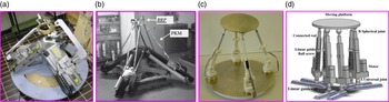
The disadvantage of the current reconfigurable parallel manipulators is that the linear motion mechanisms are widely used to adjust the positions of lower joints. The parallel manipulator is actively configured to adapt to the different working environments. Most of the time, each linear motion mechanism is actuated by a complete system (i.e., motor, controller, and actuator), which complicates the structure and controller design of the system. More importantly, the fully actuated parallel system with redundant DoF in actuators may cause difficulty in initializing/calibrating the system, leading to collisions among limbs. For example, a 3-DoF reconfigurable parallel manipulator was fabricated by Palpacelli et al. [Reference Palpacelli, Carbonari, Palmieri and Callegari15], in which three linear motion mechanisms were adopted to adjust the positions of lower joints. Then, a kind of mobile parallel–serial hybrid manipulator was researched by Tosi et al. [Reference Tosi, Legnani, Pedrocchi, Righettini and Giberti16], in which a 3-DoF reconfigurable parallel manipulator (i.e., using three linear motion mechanisms to adjust the position of lower joints) was combined with a mobile manipulator. After that, the motion planning of a reconfigurable parallel manipulator (i.e., 4-UPS mechanism) was implemented by Grosch et al. [Reference Grosch, Di Gregorio, López and Thomas30], in which the positions of lower joints were adjusted by the lockable revolute joints. Further, a kind of 6-DoF Stewart-based reconfigurable parallel manipulator was analyzed by Chen for the maximum dynamic load-carrying capacity [Reference Chen17], seen in Fig. 1.
Examples of the reconfigurable full-actuated parallel manipulators with a build-in actuator in each limb. (a) 3-DoF parallel manipulator for multimodal tasks [Reference Palpacelli, Carbonari, Palmieri and Callegari15]; (b) 3/4-DoF parallel hybrid manipulator [Reference Tosi, Legnani, Pedrocchi, Righettini and Giberti16]; (c) lockable revolute joints-based reconfigurable parallel manipulator [Reference Grosch, Di Gregorio, López and Thomas30]; (d) 6-DoF reconfigurable Stewart parallel manipulator [Reference Chen17].

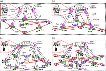
To address these research challenges, in this paper, a novel kind of underactuated positioning system with arbitrary numbers of positioning lines was proposed to be used in the design of reconfigurable parallel manipulators (Fig. 2). Specifically, the positioning ability of each positioning line can be achieved based on the design of a smart clutch (i.e., integrating the clamping and locking functions) [Reference Ma, Dong and Arreguin21]. In addition, the closed cable was adopted to transmit the motion, which enables the arbitrary distribution of positioning lines.
Different configurations of underactuated positioning systems for actuating the parallel mechanisms. (a) 3-UPU mechanism actuated by circle-configured positioning system; (b) 3-UPU mechanism actuated by star-configured positioning system; (c) 6-SPS mechanism actuated by circle-configured positioning system; (d) 6-SPS mechanism actuated by the star-configured positioning system. Note: C1–C6 and L1–L6 represent the clutches and legs, respectively.

Specifically, the underactuated positioning system can be configured in the following applications:
-
1. Circle configuration: Figure 2(a) and (c) present the circle configuration of an undenatured positioning system for actuating the 3-DoF and 6-DoF mechanisms, in which the positioning lines are located at the sides of triangle and hexagon, respectively. These configurations can increase the adjustability of the parallel mechanism in rotation items.
-
2. Star configuration: Figure 2(b) and (d) illustrate the star configuration of the underactuated positioning system, in which the positioning lines are located at the three and six redial lines, respectively. These configurations can improve the adjustability of the parallel mechanism in height items.
-
3. Arbitrary configuration: The positioning lines of the underactuated positioning system presented in this paper can be arbitrarily configurated (i.e., a combination of the circle-configuration and star configuration) to adapt to the environment. Due to the variety of actual applications in arbitrary configuration, the examples are not listed in this part.
3. Case study: A circle-configured underactuated positioning system
The novel underactuated positioning system, which is constructed by a set of positioning lines (i.e., three in this paper) and motion transmission system (i.e., closed-loop cable), is proposed in this paper to realize the independent motion of each positioning line with only one actuator. More importantly, the long-distance motion transmission and simplified system structure can improve the motion flexibilities of complex mechanisms (i.e., assembling line).
To achieve the single-input and multi-output function of the positioning system, a novel kind of SMA wire-based clutch is proposed to be combined with each positioning line, which can automatically clamp and release the moving cable to realize the synchronized motion with the cable. As a result, the number of positioning lines (i.e., one, two, or more) in moving can be controlled by adjusting the working condition of the SMA clutch (i.e., power on or off). In addition, due to the structural design of the SMA clutch, the positioning line can be locked with the base by introducing a kind of interlock mechanism when the SMA clutch is power off. Promisingly, the idea of combining the SMA clutch with a positioning line to make the underactuated system provides a method for further constructing the underactuated parallel manipulators (i.e., 3-UPU, 3-RPS, and 6-UPS).
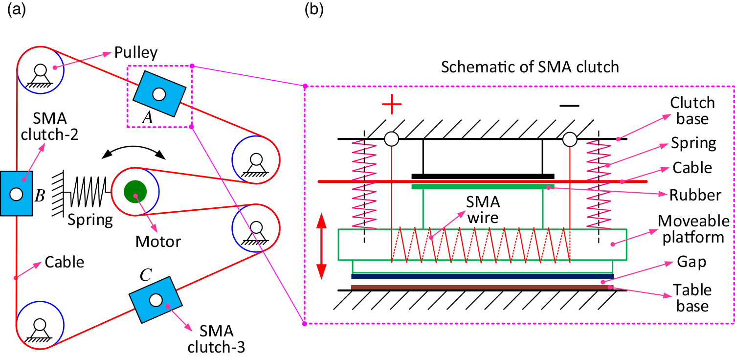
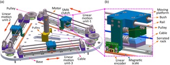
The schematic design of the underactuated positioning system and SMA clutch are shown in Fig. 3. Three positioning lines are adopted at the sides of the triangle in this system, which are actuated by one centrally located motor.
The schematic of the positioning system and SMA clutch. (a) Schematic design of underactuated positioning system with three positioning lines to achieve the independent motions: (b) Schematic of SMA wire-based clutch.

Figure 3(a) displays the schematic of an underactuated positioning system with three positioning lines located at the sides of a triangle. The annular cable is circumferentially arranged around the triangle table with the guide of pulleys, which is driven to rotate by a centrally located motor. To keep the tension of the cable to improve the performance of the system, a tensioner (i.e., driven by a spring) is introduced to be connected with the moveable pulley. The SMA clutch is inserted in each underactuated positioning system to clamp and release the moving cable, then to achieve the synchronized motion with the cable.
Figure 3(b) presents the schematic of the SMA wire-based clutch, in which the SMA wire is adopted as the actuator to achieve the reciprocating motion of the moveable platform. The long SMA wire is twinned around the clutch base and moveable platform to actuate the movement of the moveable platform. Then, the interlock characteristic of the positioning line can be produced by the moveable platform. Specifically, the moveable platform will be contacted with the table base when the SMA wire is in a martensite state (i.e., power off) while breaking away when the SMA wire is in an austenite state (i.e., switch on). In addition, the compressive springs are utilized to provide the restoring force for the SMA wire when the power is off.
3.1. SMA-based clutch
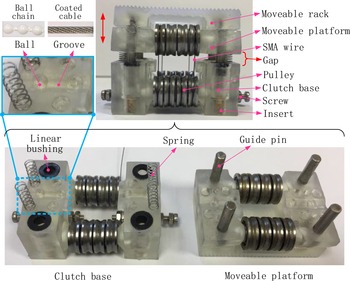
The prototype of the SMA clutch is shown in Fig. 4 based on the schematic of Fig. 3(b). The long SMA wire, which is fixed by the screws on the two ends, is twinned around the shafts of the moveable platform and clutch-based to realize the linear motion of the moveable platform. The SMA wire, otherwise the SMA spring, is utilized as the actuator for the SMA clutch. The reason is that the higher working reliability and clamping force can be achieved by using the SMA wire. When the current is applied on the two ends of the SMA wire, the effective length of the SMA wire will be changed (i.e., shorten) due to the phase transformation, where the motion of the moveable platform will be produced.
As the strain of SMA wire is relatively tiny (about 4%) compared with the stroke requirement of the clutch, the long SMA wire is utilized and twinned around the shafts of the moveable platform and clutch base. To reduce the friction caused by the relative slide between SMA wire and shafts during phase transformation, the small groove pulleys are utilized to guide the motion of the SMA wire. In addition, as the linear movement of the moveable platform is required, four sets of linear bushings and guide pins are utilized, which are installed in the moveable platform and clutch-based separately. This clutch is designed for two applications: one is to clamp the PVC-coated cable; another is to clamp the ball chain. In this paper, the coated cable is selected as an example in constructing the positioning system, and the corresponding performances of the SMA clutch in clamping the PVC-coated cable will be tested in the following.
The operational flow for the SMA clutch can be described as follows (Fig. 4): firstly, the clutch base is regarded to be fixed on the ground/base, while the moveable rack (i.e., attached with moveable platform) can realize the reciprocating linear motion; then, in the initial stage, the moveable rack is open with the clutch base by the preset force of the four compression springs; after that, when the current is applied on the SMA wire, the moveable rack is moving towards the clutch base to clamp the centrally located cable; at last, when the current is off, the moveable rack is moving back to the initial position by the four springs.
The parameters of the SMA wire used in the clutch.

As the SMA wire can only realize the one-way strain during temperature variation (i.e., contract when the temperature increases), the extra force should be imposed to push it back to the initial position when the temperature decreases. In this paper, the SMA clutch is designed to realize the reciprocating motion; the compression springs are adapted to be located between the moveable platform and clutch base. In order to achieve the high working frequency of the SMA clutch, the suitable parameters of SMA wire and spring should be selected.
The parameters of the SMA wire used in the clutch are shown in Table I.
The parameters of the compression springs used in the SMA clutch.

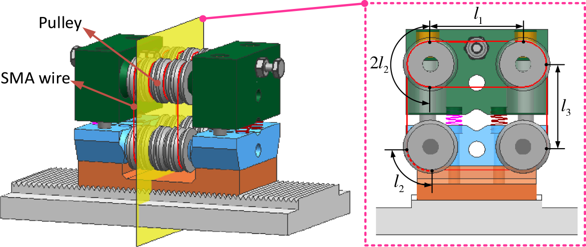
The stroke and clamping force of the SMA clutch are much related to the twinning method of SMA wire, which should be carefully planned to improve the performance of the SMA clutch in the beginning. After many attempts, one way of twinning the SMA wire, shown in Fig. 6, can generate a better performance of the SMA clutch, which is selected to proceed with the following research (i.e., modeling and performance test).
The prototype of the SMA wire-based clutch.

The structure design of the SMA clutch-based positioning system. (a) The overall structure design of positioning system; (b) structure design and assembling method of SMA clutch.

The contraction definition between SMA wire and miniature pulleys.

Four compression springs are placed between the clutch base and moveable platform symmetrically, and the parameters of them are shown in Table II.
The force in the SMA wire produced by the phase transformation has many relationships with the temperature in the SMA wire. In the initial stage, the SMA wire is fully assumed to be in the martensite phase. With the increase of the temperature, the phase is gradually transformed into austenite. During this process, the strain/stress in the SMA wire is increasing with the degree of phase transformation (i.e., from martensite to austenite), where the motion in the moveable platform will be produced. In order to achieve the successful working of the SMA clutch in the underactuated positioning system, the SMA clutch should be carefully designed (i.e., length of SMA wire, numbers of spring, and stroke of the clutch) based on the model presented in Section 3.2.
3.2. Underactuated positioning system
Based on the schematic design of the underactuated positioning system (Fig. 3(a)), three positioning lines are adopted to achieve the underactuated motions as the case study in this paper. However, more numbers of positioning lines can be assembled in the system based on the proposed underactuated method, which can be utilized to actuate the multi-DoFs mechanisms (e.g., 3-UPU, 3-RPS, and 6-UPU) with only one actuator input. In addition, the positioning lines in the underactuated positioning system can be arbitrarily distributed/planned due to the unique motion transmission method (cable), which brings the advantages to optimize overall performances of the underactuated parallel system (i.e., positioning system and parallel mechanism together).
As documented in the last paragraph, the underactuated positioning system is constructed by one motion transmission system and several positioning lines (Fig. 5). To illustrate the structure of the underactuated positioning system, it is divided into two aspects:
Motion transmission system: The Maxon motor (type: DCX32L) with the reducer (type: GPX32 with 138 ratios) and encoder (type: ENC16 with 1024 pulses) is located at the center of the base platform, which is utilized to actuate the moving of the cable. Four pulleys are installed at the corners of a triangular plate to guide the motion of the cable. In addition, the tensioner mechanism is utilized to keep the tension of the cable for improving the performance of the system.
Positioning line: The positioning line is the mechanism to realize the linear motion of the positioning system, which is composed of the guide mechanism, positioning mechanism, and feedback mechanism, respectively (Fig. 5(b)). Specifically, the bush and linear shafts are utilized to improve the motion performance of the moving platform, in which the SMA clutch is installed to achieve the positioning and locking characteristics; in addition, the displacement sensor (type: RLC2IC; resolution: 0.244 µm) was adopted to feedback the position of positioning the line.
The underactuated positioning system, which comprises three positioning lines and a motion transmission mechanism, is selected as a case study to validate the novel idea proposed in this paper. The performances of the SMA clutch (i.e., clamping force and stroke), which are the key factors to decide the performance of the positioning system, should be carefully designed. To improve the performance of the positioning system, the model of SMA clutch is established in the next section, enabling to guide the operation of SMA clutches for three positioning lines.
4. SMA clutch modeling
As the SMA clutch is a vital component to decide the responses of the linear motion system, further to complete the entire performance of the underactuated positioning system, the constitutive heat equation of SMA wire was established to calculate the responses in stress and strain, further to develop the model of SMA clutch. The novelty of the heat dissipation model developed in this paper considers the heat dissipation from SMA wire to the steel pulleys and air, respectively. Then, the overall model of the SMA clutch can be built [Reference Arghavani, Auricchio, Naghdabadi, Reali and Sohrabpour31, Reference Brinson32, Reference Liang and Rogers33] to theoretically study the displacement response of the SMA clutch under different voltage inputs.
4.1. Modeling SMA wire
As the SMA material is sensitive to temperature, which will be damaged if the temperature is higher than the
 $A_{f}$
, the temperature in SMA material should be carefully controlled. In practical application, the electricity is mainly utilized to heat the SMA material, further managing the phase transformation. Specifically, as the average voltage is easy to be controlled by using the pulse width method (PWM), it was selected to adjust the average voltage on the SMA clutch in this paper.
In addition, based on the structure design of the SMA clutch, the miniature pulleys (i.e., steel material) are utilized in the design of the SMA clutch, which will influence the heat dissipation speed of the SMA wire. Thus, the heat in SMA wire can be dissipated into two ways, and they are steel pulleys and air, respectively.
The energy conservation equation of SMA wire can be established as follows [Reference Guo, Pan, Wee and Yu25]:
 \begin{equation} \frac{V^{2}}{R}=m_{w}c_{w}\dot{T}+D_{1}+D_{2} \end{equation}
Where
 $V$
is the voltage imposed on the SMA wire;
 $R$
is the resistance of the SMA wire;
 $m_{w}$
is the mass of the SMA wire;
 $c_{w}$
is the heat constant-coefficient;
 $\dot{T}$
is the temperature change rate of the SMA wire;
 $D_{1}$
and
 $D_{2}$
are the heat dissipated from the SMA wire to air and steel pulley, respectively, which can be expressed as
 \begin{align} D_{1} & =hA_{w}\left(T-T_{\mathrm{amb}}\right)\nonumber\\ D_{2} & =hA_{p}\frac{dT}{dt}\end{align}
Where
 $h$
is the heat convection factor, which can be expressed as
 $h=h_{0}+h_{2}T_{2}$
.
 $A_{w}$
is the surface area of SMA wire.
 $T$
is the current temperature of the wire.
 $T_{\mathrm{amb}}$
is the ambient temperature.
 $\lambda$
is the coefficient of thermal conductivity;
 $A_{p}$
is the contact area of the pulley with the SMA wire;
 $d_{T}/d_{t}$
is the temperature gradient from the SMA wire to the pulley.
To increase the stroke of SMA clutch and reduce the relative sliding friction between SMA wire and shafts, the long SMA wire is twinned around the miniature pulleys (Fig. 6). The parametric heat dissipation equation of the proposed SMA clutch is established by considering heat dissipation, which is then utilized in modeling the SMA clutch.
Based on the heat dissipation law, the contacting area is the primary factor to influence the heat dissipation speed and further decide the temperature of the SMA wire. Thus, the contacting regions of SMA wire with different heat dissipation ways (i.e., air and pulley) are defined firstly. Specifically, as the SMA wire used in the clutch is a long wire with a constant circular cross-section, the contacting areas are determined by the length of the SMA wire. The wire is defined into three kinds to define the contacting areas among the two different energy dissipation ways. Established by substituting
 $A_{w}$
and
 $A_{p}$
in formula (2) can be defined as
 \begin{align} A_{w} & =\left(n_{1}l_{1}+n_{2}l_{3}\right)s_{1}\nonumber\\ A_{p} & =\left({\sum }_{i=1}^{n}k_{i}l_{2}\right)s_{2} \end{align}
Where
 $l_{1}$
is the horizontal length of the wire between two pulleys;
 $l_{2}$
is the length of the wire in the quarter circumference of the pulley;
 $l_{3}$
is the vertical length of the wire between two pulleys;
 $n_{1}$
is the number of sections in
 $l_{1}$
length;
 $n_{2}$
is the number of sections in
 $l_{2}$
length;
 $s_{1}$
is the unit surface area of the SMA wire.
 $n$
is the number of sections contacting with the pulley;
 $k_{i}$
is the coefficient of the connect length (i.e.,
 $k_{i}=1$
or
 $k_{i}=2$
);
 $l_{2}$
is the length of the wire contact with the pulley;
 $s_{2}$
is the unit contacting area of the wire with the pulley.
Thus, the energy conservation equation of the SMA clutch can be established by substituting Eqs. (2) and (3) into Eq. (1); then, the temperature variation of SMA wire can be calculated after specifying the voltage imposed on the SMA clutch; after that, the constitutive equation of SMA wire for calculating the stress and strain responses can be established as
 \begin{equation} \dot{\sigma }=E\dot{\varepsilon }+\Omega \dot{\xi }+\Theta \dot{T} \end{equation}
Where
 $E$
is Young’s modulus;
 $\Omega$
is the phase transformation coefficient;
 $\Theta$
is the thermo-elastic coefficient;
 $\dot{\sigma }$
,
 $\dot{\varepsilon }$
,
 $\dot{\xi }$
, and
 $\dot{T}$
are the variation rate of stress, strain, martensite fraction, and temperature, respectively.
As a result, based on Eq.(4), the stress and strain of SMA wire can be calculated after specifying the initial conditions of stress, strain, martensite fraction, and temperature. Then, the displacement response of the SMA clutch can be achieved by establishing the static model, which is shown in Section 4.2.
4.2. Modeling SMA clutch
To achieve the positioning and locking function of positioning the line, the stroke and clamping force of the SMA clutch should be carefully designed. Specifically, they should be satisfied with the following requirements after the full phase transformation of SMA wire from martensite to austenite (Note: the coiling method of SMA wire in the clutch is shown in Fig. 6):
(a) Stroke: as the SMA wire has limited strain during the phase transformation, the gap between moveable platform and clutch base (Fig. 4) should be less than the maximum strain of SMA wire, which can be expressed as
 \begin{equation} d_{c}+b_{b}=d_{\text{stroke}}\lt \frac{l\varepsilon }{4} \end{equation}
Where
 $d_{c}$
is the distance of movable platform with cable;
 $d_{b}$
is the distance between the moveable platform with table base.
(b) Clamping force: as the compressional springs are introduced in the SMA clutch to push the SMA wire back to the initial position after the power off, the parameters of springs (i.e., stiffness and initial length) should be carefully selected to match with the SMA wire. In addition, the effective clamping force of the SMA clutch,
 $F_{c}$
, decides the operating performance of the positioning line. Thus, the following equation can be satisfied:
 \begin{equation} F_{c}\gt F_{\text{required}} \end{equation}
Where
 $F_{c}$
is the effective clamping force of SMA clutch;
 $F_{\text{required}}$
is the required clamping of the SMA clutch.
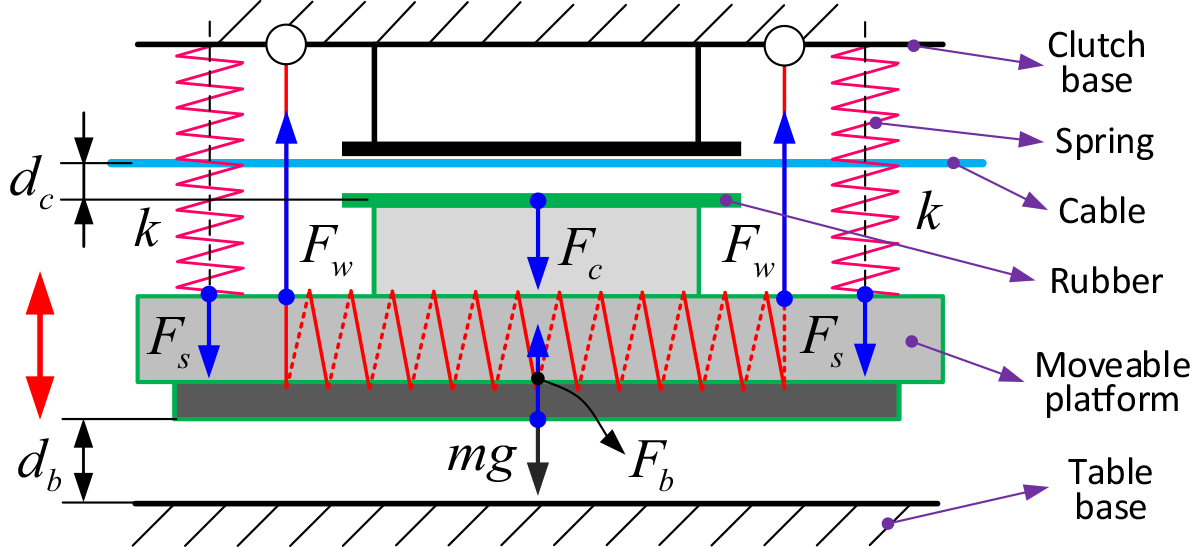
Figure 7 presents the static schematic of the SMA clutch. To facilitate the modeling of SMA wire, the primary forces in the SMA clutch are selected.
The static schematic of the SMA clutch.

Based on the static analysis, the static model of the SMA clutch can be established as Eq. (7), in which two working stages (i.e., closing and clamped stages, respectively) of the SMA clutch are considered.
 \begin{align} \begin{cases} 4kd_{0}=F_{b} & d_{b}=0\\[5pt] 4k\left(d_{b}+d_{0}\right)+mg=4F_{w} & 0\lt d_{b}\lt d_{\text{stroke}}\\[5pt] 4k\left(d_{b}+d_{0}\right)+F_{c}+mg=4F_{w} & d_{b}\geq d_{\text{stroke}} \end{cases}, \end{align}
Where
 $k$
is the stiffness of the spring;
 $d_{b}$
is the displacement of the moveable platform;
 $d_{0}$
is the initially compressed distance of spring;
 $m$
is the mass of the moveable platform;
 $g$
is the gravitational acceleration;
 $F_{b}$
is the clamping force of the moveable platform with table base in the initial stage;
 $F_{w}$
is the pulling force of the SMA wire;
 $F_{c}$
is the clamping force on the cable;
 $d_{\text{stroke}}$
is the maximum displacement of the SMA clutch.
Based on the installation of the compressing springs (i.e., compressed distance,
 $d_{0}$
, in the initial stage), the initial conditions of the SMA wire (
 $\sigma _{0}$
,
 $\varepsilon _{0}$
,
 $\xi _{0}$
) can be defined as follows:
-
1.
 $\sigma _{0}=F_{0}/s$
. where,
$F_{0}$
is the force from the springs in the initial stage and can be expressed as:
$F_{0}=d_{0}k$
;
$s$
is the cross-section area of SMA wire.
-
2.
$\varepsilon _{0}=\sigma _{0}/E_{0}$
. where,
$\sigma _{0}$
is the strain of the SMA wire in the initial stage,
$E_{0}$
is the Young’s modulus of the SMA wire in the initial state. -
3.
$\xi _{0}=\varepsilon _{0}/\varepsilon _{L}$
. where,
$\xi _{0}$
is the martensite fraction of SMA wire in the initial stage;
$\varepsilon _{L}$
is the maximum strain of the SMA wire.


After establishing the static equation of the SMA clutch, the dynamic performances (i.e., displacement response) under different voltages can be achieved. With the help of the control hardware and algorithm developed in the next section, the performances of the SMA clutch can be tested. After that the model proposed in this paper can be validated.
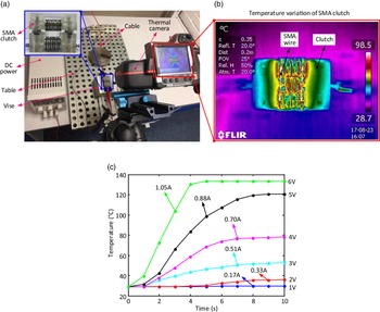
The experimental setups and results of SMA clutch. (a) Experimental setup for testing the temperature/current variations under different voltages; (b) temperature distribution of SMA clutch (i.e., 5 V); c) temperature and current variation of SMA clutch under different voltage inputs.

5. Experimental setup and performance test
In this section, after the temperature and current responses of the SMA clutch under different voltage inputs are tested by the thermal camera, the model of the SMA clutch proposed in previous sections is validated. Then, the dynamic performances of the SMA clutch, positioning line, and underactuated positioning system are tested, respectively, with the designed control algorithm.
5.1. SMA clutch performance test
As the SMA clutch is a crucial component to construct the underactuated positioning system, the parameters for deciding the performance (i.e., temperature and current responses under the voltage inputs) of the SMA clutch are implemented at first to find the suitable controlling parameters (i.e., voltage and heating time) for the following experiments of the underactuated positioning system.
5.1.1. Voltage responses and model validation
The experimental setup of the SMA clutch is shown in Fig. 8. The thermal camera (type: FLIR T540), which is supported by a camera stander to adjust the position, is used to capture the temperature distribution of the SMA clutch. The clutch is fixed on the experimental table with the help of a vice. The digital DC power supply (type: ISP 303DD) with the ability to adjust the voltage was used to power the SMA clutch. In addition, the voltage on the SMA clutch is varying from 1 to 6 V with 1 V interval, and then the temperature variations in the SMA clutch are captured by the thermal camera to be researched.
Figure 8(b) illustrates the temperature and current variations of the SMA clutch under different voltages. It can be seen from the experimental results that the higher current and temperature were produced with the higher voltages. Under the 1 and 2 V voltages, the temperatures in SMA wire change slightly within a 10-s period (i.e., from room temperature 28.7°C to about 29.5°C and 35.8°C, respectively). When the voltages imposed on the SMA clutch are higher than 2 V (i.e., from 3 to 6 V), the temperature variations in SMA wire increase rapidly, with 10 s heating time under the 3 V voltage, the temperature in SMA wire is increased to 52.7°C. With the higher voltages (i.e., 4, 5, and 6 V), the temperatures of SMA wire reach the maximums (i.e., 79.1, 120.5, and 133.5°C at 9, 8, and 4 s, respectively) rapidly, and then keep almost constant afterward. In addition, the currents are proportional with the voltages imposed on the SMA wire, and they are 0.17, 0.33, 0.51, 0.70, 0.88, and 1.05 A under the voltages 1, 2, 3, 4, 5, and 6 V, respectively.
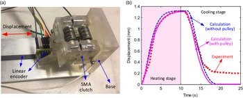
To test the displacement response of the SMA clutch, further, to validate the model proposed in this paper, the experimental setup of the SMA clutch is built as in Fig. 9(a). In the experimental setup, the SMA clutch is installed on the base with a vertical plate, in which the magnetic scale with 0.244 µm resolution is glued. The magnetic linear encode (type: RLC2IC) is installed on the moveable rack of the SMA clutch, which can feedback the position to the control system. In addition, the PWM is adopted to adjust the average voltage imposed on the SMA clutch from the power supply (i.e., 12 V).
(a) The experimental setup of the SMA clutch for implementing the model validation; (b) the improvement in modeling accuracy of SMA clutch after considering the heat dissipation of steel pullies. Note: 4V voltage was imposed.

Figure 9(b) presents the effect in increasing the modeling accuracy of the SMA clutch when considering the heat dissipation from SMA wire to steel pulleys. It can be seen from the comparison between experiments and calculations (i.e., without and with the influence of steel pulleys, respectively) that the model accuracy was significantly improved (i.e., from 7.9% error to 5.3% error) when the steel pulleys are considered in the model. During the heating stage, considering the steel pulleys in the model is more obvious to obtain the high accuracy, where the errors are 4.6% and 2.4%, respectively, without and with the consideration of steel pulleys. During the cooling stage, high accuracy is achieved when the steel pulleys are considered in the model in the beginning. However, the errors between the models (i.e., without and with the influence of steel pulleys) and experimental results are leveling off with 0.2 mm discrepancy from 15 s, where the displacement calculated from the models (i.e., without and with the influence by steel pulleys) is 0 mm but keeps 0.2 mm in the experiment results. The reason for the 0.2 mm displacement residue in the experiment may be that the crystal structure of SMA material was changed due to the heating, where a long time is needed for SMA wire back to the initial position (i.e., 0 mm).
From the responses of the SMA clutch under different voltages in this section, the suitable parameters (i.e., voltage and heating time) for controlling the SMA clutch can be selected. As the SMA wire is sensitive to the temperature, which is easy to be damaged when the temperature is higher than the austenite finish temperature (Af), the voltage and heating time on the SMA clutch should be carefully controlled. In addition, with the increase of voltage, the displacement response of the SMA clutch is significantly increased, which benefits in improving the response speed of the SMA clutch. In addition, the model proposed in this paper, which considers that the influence of steel pulleys was demonstrated as an effective way to improve the modeling accuracy of SMA-based mechanisms (i.e., 2.6% improvement).
5.1.2. Control algorithm-based performances
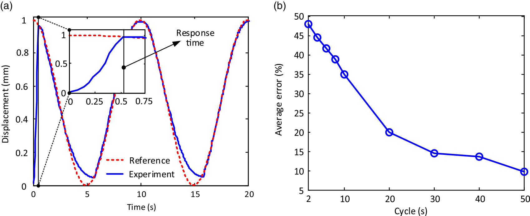
The tracking responses of the SMA clutch are shown in Fig. 10, in which the sinusoidal trajectories with different parameters (period) are selected to be tracked. In order to test the response speed of the SMA clutch for tracking the given displacement, the initial displacement of the sinusoidal trajectory in Fig. 10(a) is set as 1 mm. Then, the PID control algorithm is implemented to track it. In addition, the average tracking error is selected as the criterion to judge the performance of the SMA clutch in tracking the sinusoidal trajectories with different periods, which is shown in Fig. 10(b).
The experimental results of SMA clutch. (a) The tracking response of SMA clutch under given sinusoidal trajectory (Amplitude: 0.5 mm, cycle: 20 s); (b) the tracking error variations of SMA clutch under trajectories with different cycles (Note: the amplitudes of trajectories are 0.5 mm with 0.5 mm shifted to the positive direction).

Figure 10(a) presents the tracking response of SMA clutch under the given sinusoidal trajectory (i.e., Amplitude: 0.5 mm, cycle: 20 s), in which the reference trajectory is plotted for the comparison. The reference trajectory is starting from 1 mm, and then the SMA clutch is trying to track it from 0 mm with the implemented control algorithm. The response time of the SMA clutch (i.e., 0.52 s to attend 1 mm) can be seen from the enlarged image. It can be seen from Fig. 10(a) that the worse tracking accuracy (i.e., 43.2%) happens when the SMA clutch is working at the following two stages (i.e., at the beginning and closing to the zero points of the displacement). In comparison, better tracking accuracy (i.e., 3.4%) is achieved in the rest of the areas. The reason for the worse tracking accuracy in the beginning stage is that the SMA clutch is trying to track the given displacement (i.e., 1 mm) from the initial position (i.e., 0 mm), where the error is caused. In addition, as the heat dissipation speed of the SMA wire is decreasing seriously when the temperature of the SMA wire is closing to the room temperature, the longer time will be taken for the SMA wire back to the initial position, where the error is produced.
Figure 10(b) illustrates the average errors of SMA clutch for tracking the sinusoidal trajectories with different periods. The amplitude and phase of trajectories are kept the same in Fig. 10(a), while the periods are changed from 2 to 50 s to research the tracking performances of the SMA clutch. It can be seen from Fig. 10(b) that the overall tracking error is decreasing with the increase of the period. Specifically, the tracking error is gradually dropped from 47% with a 2-s period in the beginning to 9% with a 50-s period at the end, which means that the tracking ability of the SMA clutch is significantly increased under more considerable periods.
5.2. Underactuated positioning system test
The performance test of the underactuated positioning system is divided into two steps, which are the positioning line and underactuated system performance tests, respectively. With the help of a performance test on the SMA clutch in the previous section, the suitable control voltage on the SMA clutch is selected and utilized during the performance tests.
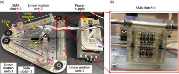
As the positioning line is one of the main components for the underactuated positioning system, to study the performance for better application, the experimental for the positioning line and positioning system are conducted separately (Fig. 11). The digital power supply (type: ISO-TECH IPS 303DD) was used to power the system (i.e., controller, motor, and SMA clutch components). The Maxon motor (type: DCX32L) with the reducer (type: GPX32 with 138 ratios) and encoder (type: ENC16 with 1024 pulses) was used to actuate the rotation of the pulley, further, to drive the moving of circular PVC-coated cable (i.e., outer diameter: 2.3 mm, inner steel wire diameter: 1.5 mm). Three identical positioning lines, which are constructed by SMA clutch, guin clamping the PVC coated iding system, and encoding system (Fig. 11(b)), are located at the three sides of the triangle. Three linear encoder systems (receiver: RLC2IC and magnetic scale: 0.244 µm resolution) are used to feedback the positions of three positioning lines.
Experimental setup of positioning line and underactuated positioning system (a), and assembling characteristic of SMA clutch in positioning line (b).

5.2.1. Positioning line performances
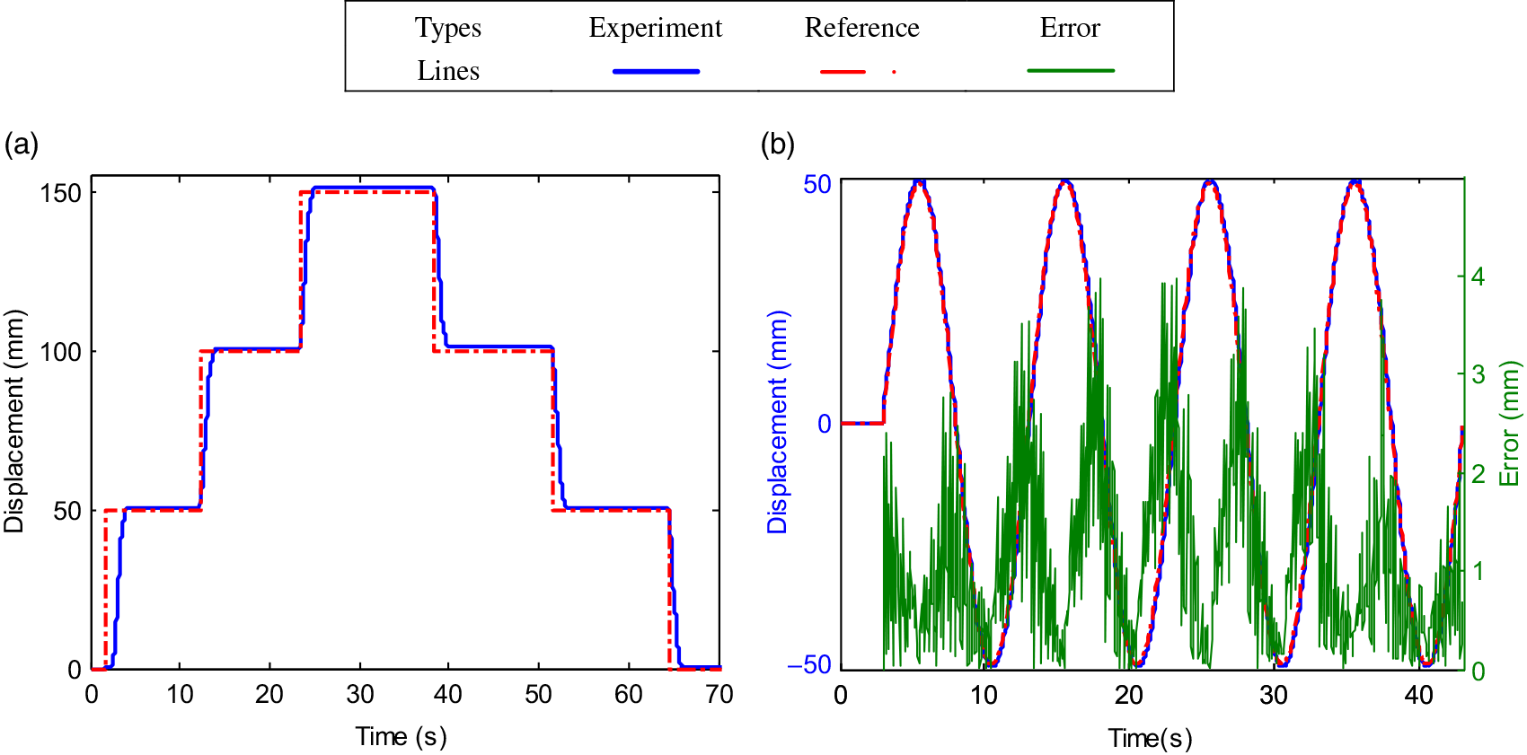
One positioning line (i.e., positioning line 1) in the underactuated positioning system is selected for the performance tests (i.e., step and tracking responses, respectively), shown in Fig. 12. The steps with a 50-mm increment or decrement are added to the system to test the performances (i.e., response time and positioning accuracy) of the positioning line (Fig. 12(a)). Then, the tracking response of the positioning line with the sinusoidal trajectory (i.e., amplitude: 50 mm, period: 20 s, and phase: 0°) is performed, which is shown in Fig. 12(b).
Figure 12(a) presents the step response of one positioning the line, in which the displacement increases from 0 to 150 mm with 50 mm intervals at the first half of the test, and then decreases from 150 to 0 mm with 50 mm intervals at rest half of the test. From the experimental results (i.e., beginning of the figure), it can be found that it takes about 2 s for the SMA clutch to clamp the cable fully. After that, the control algorithm can be implemented to actuate the positioning line to the expected position. In addition, the response time and positioning error for each step are listed in Table III.
Figure 12(b) displays the tracking response of the positioning line for sinusoidal trajectory (i.e., amplitude: 50 mm, cycle: 20 s, and phase: 0°). As it has to take some time (i.e., around 2 s) for the SMA clutch to clamp the cable, the tracking motion is started at 2 s at the beginning, which is an inessential procedure for obtaining accurate tracking performance. It can be seen from the experimental results that the underactuated positioning system can track the given sinusoidal trajectory with high accuracy. Due to the rotation speed limitation of the motor, the higher errors are produced when the positioning line is closing to the zero point, and the error peak can attend to 10 mm. However, the tracking error is relatively small (i.e., less than 1 mm) in the rest of the parts.
The response time and positioning error for step responses of the positioning line.

Note: Exp means the experimental result; Reference means the reference result in Fig. 10(a).
The experimental tests on one positioning line. (a) The step response of the positioning line with different step inputs (i.e., from 0 to 150 mm with 50 mm interval in increasing stage, and from 50 to 0 mm with 50 mm interval in decreasing stage); (b) the tracking response of positioning line under given sinusoidal trajectory (i.e., amplitude: 50 mm, period: 20 s and phase: 0°).

5.2.2. Performances of the underactuated positioning system
The experiment on the underactuated positioning system is to test the decoupled moving characteristics (i.e., clamping feasibility and positioning accuracy) of the three positioning lines, which will decide the performance of the parallel manipulator to be connected with a parallel mechanism (e.g., 3-UPU, 3-RPS, and 6-UPS), shown in Fig. 13.
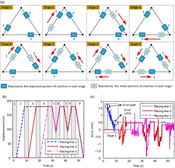
The trajectories planning and experimental tests of the underactuated positioning system. (a) The decoupled motion planning of the three positioning lines; (b) the experimental results (i.e., motion sequences) of the three positioning lines with the consideration of the working characteristics of SMA clutch; (c) the corresponding tracking errors in three positioning lines.

The experimental setup of the underactuated positioning system is shown in Fig. 11. As the positioning system is actuated by one motor, the motions of the three positioning lines should be planned at first, which are shown in Fig. 13(a). The serial movements of the three positioning lines are scheduled as following nine stages: in stage 1, the three positioning lines are in the initial positions; in stages 2, 3, and 4, the three positioning lines (i.e., positioning lines 1, 2, and 3, respectively) are moving to the desired destinations (i.e., 160 mm) separately; in stages 5 and 6, the three positioning lines have the reciprocating motions simultaneously from 160 to 80 mm, and then back to 160 mm; in stages 7 and 8, the two positioning lines (i.e., positioning lines 1 and 2) are having the reciprocating motions simultaneously from 160 to 80 mm, and then back to 160 mm; in the last stage, the three positioning lines are moving back to the initial positions simultaneously.
Figure 13(b) displays the experimental results of the three positioning lines planned in (a). Due to the characteristics of the SMA clutch (i.e., extra time needed for the clamping and releasing), the time sequences for the three positioning lines should be carefully planned to improve the performance of the positioning system. Precisely, for actuating any positioning lines (i.e., move or stop), the embedded SMA clutches should be fully clamped to the cable before moving the positioning line, and the SMA clutches in other positioning lines should be fully released from the cable. Thus, the extra time (i.e., 3 s) is added before actuating the discontinuous motions of the positioning lines (i.e., in stages 1, 2, 3, 4, 5, 7, and 9).
Figure 13(c) presents the tracking error of three positioning lines in performing the decoupled motions. It can be seen from the experimental results that the errors are within ±2 mm during the whole period of moving. Taking the stage 2 as the example, the tracking error is peaking in the initial and then drops gradually. The large error happened at the beginning, which may be caused by the following reasons: firstly, the relative sliding between the SMA clutch and cable is occurred due to the low clamping force of the SMA clutch; secondly, the higher acceleration exists at the beginning of planned trajectory, in which the error is produced. At the end of stage 2, the tracking error is jumping to around 0.5 mm and is then kept unchanged. The reason for the jumped error is that the serrated rack is utilized in the positioning line, which makes the two serrated racks (i.e., in SMA clutch and base, respectively) engaged together after the SMA clutch is released from the cable, where the error is produced.
6. Example demonstration
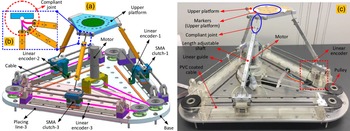
With the physical underactuated positioning system and control system, the positions of the three lines can be controlled independently with high accuracy (average error: 1.01%). To demonstrate the advantages of the proposed system, a compliant parallel manipulator with three limbs was integrated on the placing lines, and the positions can be controlled/adjusted to change the configuration of the parallel manipulator as seen in Fig. 14. It has been demonstrated in previous research that upper platform can achieve the 6-DoF motion by changing the position of the three limbs, while the aim of this section is to show the advantages of the underactuated positioning system (i.e., using one motor to control the motion of a multiple DoF manipulator).
An example application of the proposed underactuated positioning system, which is constructed by combing with the compliant parallel manipulator to reduce the number and weight of the system: (a) and (b) are the 3D model of the structure design; (c) is the prototype of the underactuated positioning system.

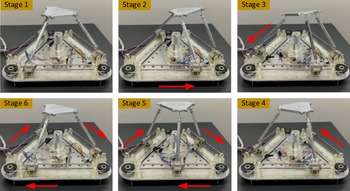
By changing the position of the three lines, the configuration of the parallel manipulator can be adjusted, enabling to control the 6-DoF motion of the upper platform (i.e., three transitional motion and three rotational motion) by one motor. As a case study, an example motion sequences of the three placing lines are planned to demonstrate the capability of our system. The snapshots of the configuration variation of the compliant parallel manipulator under different inputs are shown in Fig. 15.
Snapshots of the compliant parallel manipulator actuated by the developed underactuated positioning system to adjust the position/pose of the upper platform.

It can be seen from Fig. 15 that the configuration of the 6-DoF compliant parallel manipulator can be adjusted with the proposed underactuated positioning system, which demonstrates the feasibility of using one motor to actuate the multiple DoF manipulators. With the single motion of the positioning line from stages 2 to 4 (i.e., one positioning line moves, while the rest two positioning lines keep stationary), the posture of the upper platform (e.g., pitch angle) can be adjusted drastically. While when the three positioning lines are moving simultaneously, the rotational motion of the upper platform, which is the primary motion, can be achieved.
7. Conclusion
In this paper, a novel cable-driven underactuated positioning system, which is constructed by different sets of positioning lines (i.e., three as the example study in this paper), is proposed based on a smart design of SMA clutch, thus, enabling the following advantages of the positioning system to be achieved (i.e., arbitrary arrangements and decoupled motions of positioning lines). Promisingly, the underactuated positioning system can be utilized as the multimotion platform for different applications (i.e., parallel mechanism actuation and remote motion transmission).
For the first time, a novel SMA wire-based clutch, which is the critical component for achieving the positioning and locking functions of the positioning line, is modeled, and tested in this paper. Based on the intelligent structure and modeling method of the SMA clutch, the following results can be concluded: firstly, considering the heat dissipation of the miniature steel pulleys has a significant influence on the model accuracy of the SMA clutch (i.e., improving 2.6% accuracy); secondly, the model of SMA clutch proposed in this paper can be validated by the voltage response with error 5.3%; in addition, the clamping speed of SMA clutch (i.e., 2 s to the steady output under 3 V voltage) is much quicker than releasing time (i.e., 15 s back to the initial position after power off); at last, the individual experiments on SMA clutch indicate that it can achieve the high accurate tracking performance (i.e., 19.6% error of sinusoidal trajectory, amplitude: 0.5 mm, cycle: 20 s).
Further, after experimentally testing the performances of one positioning line (i.e., positioning and tracking accuracy), the performance of the underactuated positioning system (i.e., the decoupled motion of positioning lines) is tested. The results of single positioning line can be concluded: firstly, in order to avoid the relative sliding between SMA clutch and cable, the extra time (i.e., 3 s) is needed for the SMA clutch to clamp and release the cable; secondly, the positioning line can realize high performances in positioning (i.e., average error: 1.01%) and tracking (i.e., average error
 $\leq$
1 mm). The experiments on underactuated positioning system indicate that it can realize the decoupled motions in three positioning lines (i.e., three positioning lines move in sequence and two or three positioning lines move simultaneously), and the overall tracking error in decoupled motions is less than ± 2 mm within 180 mm moving range.
At last, by combing the developed underactuated positioning system with an example 6-DoF compliant parallel manipulator, the feasibility of using one motor to actuate the multiple DoF manipulator has been demonstrated. It was found that the motion characteristic of the 6-DoF parallel manipulator can be actively designed by changing the motion pattern of the underactuated positioning system, enabling it to be an ideal actuation system (advantages: lightweight and power efficient) for the parallel manipulator to achieve some special functions (e.g., solar panel of satellite).
Acknowledgment
The research leading to these results has received funding from China Scholarship Council and University of Nottingham.
Conflict of interest
The author(s) declare(s) that there is no conflict of interest.