I. INTRODUCTION
Development of ultra-wideband (UWB) systems has increased the demand for compact antennas that can be economically manufactured and possess omni-directional radiation patterns. It is well known that printed monopole antennas have attractive features, namely: (1) large impedance bandwidth; (2) ease of fabrication using conventional MIC technology; (3) acceptable radiation properties; and (4) light weight. Consequently such antennas have received great attention for UWB applications. In fact, since the Federal Communications Commission (FCC) launched the bandwidth defined between 3.1 and 10.6 GHz [1] for commercial use, UWB technology has now become the favored choice for short-range and high-speed indoor data communications.
Several printed monopole antennas with different geometries have been reported recently [Reference Pourahmadazar, Ghobadi, Nourinia and Shirzad2–Reference Jiang, Song, Yan, Zhang and Wu15]. Unfortunately UWB systems have to operate in an electromagnetic spectrum occupied by several narrow band signals used by wireless communication systems such as wireless local-area network (WLAN) IEEE802.11a and HIPERLAN/2 WLAN operating in 5–6 GHz band. This necessitates the use of filters to suppress these much stronger interfering signals that would otherwise degrade the operation of UWB systems. However, this requirement would unnecessarily increase the complexity, weight and volume of the UWB systems. Hence additional functionality is required from UWB antennas. Over the recent years numerous antennas have been developed to eradicate electromagnetic interference between the UWB and other narrowband systems such as WLAN. Over recent years various printed antennas have been reported for application in UWB systems using different structures and feed methods such as coplanar waveguide, coaxial and microstrip. Xie et al. [Reference Xie, Jiao, Zhang and Song6] used proximity coupled resonator, Zhao et al. [Reference Zhao, Jiao, Zhao, Zhang, Song and Wong7] proposed a slotted planar antenna using π-shaped slot. In [Reference Movahedinia and Azarmanesh8] band notch function based on slot-type electric LC resonator on patch has been presented. Wu et al. [Reference Wu, Kang, Chen and Tarng9] described applying an open-looped resonator, and Cho et al. [Reference Cho, Kim, Choi, Lee and Park10] in reference proposed a U-shaped filter in radiating element. For WLAN-notched operation, a slot with semi rectangular shape has been used in [Reference Shagar and Wahidabanu11]. Segmenting a circular patch to create a stop-band is presented in [Reference Zhang, Li and Long12]. To realize the rejection band inverted U-shaped slot is added in the hexagonal patch in [Reference Mandal and Das13]. Other techniques include: slotted arc-shaped edge rectangular antenna [Reference Hong, Ling, Tarn and Chung14], and utilizing a pair of inverted-L-shaped slots on the ground-plane [Reference Jiang, Song, Yan, Zhang and Wu15].
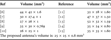
In this paper we present the results of the proposed antenna that exhibits a VSWR ≤2 in the frequency band between 2.50 and 12.12 GHz, with a notch band frequency between 5.02 and 5.93 GHz (both simulated). The antenna has been analyzed using Ansoft High Frequency Structure Simulator (HFSS) [16]. The experimental results show the antenna has an impedance bandwidth of 8.95 GHz between 2.58 and 11.53 GHz (126.8%). A compact, yet structurally simpler configuration is proposed. Table 1 compares the size of the proposed antenna with similar type of antennas previously published. The table reveals the proposed antenna is more compacter. The antenna radiates stable H-plane radiation pattern over its operational frequency range, and possesses ultra-wide impedance bandwidth that can be altered by modifying the antenna's aperture dimensions. In addition, an open-loop inverted triangular-shaped slot (TSS) etched in the patch provides band-stop performance at a specific frequency determined by its dimensions. Details of the antenna design are presented, and comparison between simulated and measured results of voltage standing-wave ratio, and radiation patterns and antenna gain are given.
Volume of some previous antennas for comparison with this work.

II. ANTENNA DESIGN
Figure 1 shows the geometry of the proposed antenna. The compact antenna occupies an area of 25 × 25 mm2 when constructed on the FR4 dielectric substrate with a relative permittivity of 4.4, a thickness of 0.8 mm and tan δ = 0.02. An SMA connector is used to feed the antenna through a 50 Ω CPW transmission-line with a strip width of 3.1 mm and gap width of 0.3 mm. The primary antenna structure consists of radiating patch and a slotted CPW ground. The main features desired from this antenna are: (1) its ability to operate across UWB as defined by Federal Communications Commission; and (2) ability to reject unwanted WLAN interfering band from affecting the UWB operation. To achieve the first aim three different patch configurations have been studied, which are shown in Fig. 2. The three antennas have the same aperture, feed-line, and ground-plane.
The results show the dome-shaped patch provides the widest impedance bandwidth (IBW) of 131%. The triangular patch provides IBW of 88%, and the rectangular patch has an IBW of 124%. Reflection-coefficient (S 11) as a function of aperture area (L × W) in Fig. 3 shows the widest impedance bandwidth is achieved with aperture with dimensions of 14 × 23 mm2. To achieve the second requirement the dome-shaped patch is embedded with an open-loop inverted triangular-shaped slot, as illustrated in Fig. 1. The slot interacts with surface currents over the patch to generate a stop-band. The Smith Chart plotted in Fig. 4 provides some insight to this phenomenon. By embedding the TSS leads to capacitance enhancement that prevents radiation over a specific narrowband. Fig. 5 shows the current density distribution and electric-field vectors over the patch at the notch frequency (5.5 GHz).
Geometry of the proposed antenna with defining parameters of: W s = 4, L s1 = 0.5, and L s2 = 0.75. (optimized dimensions in mm).
S 11 curve comparing three different antenna patch configurations.
S 11 curve for various aperture areas (L × W) as a function of frequency.
Smith Chart of the antenna (a) for antenna with no slot and (b) antenna with the open-loop inverted TSS.
Surface current density distribution and electric-field vectors over the patch at 5.5 GHz.
At the notch frequency the electric-field vectors are more dominant around TSS. The vectors around the slot are in opposite direction resulting in cancellation of signals predominately at or very close to a specific frequency determined by slot length. The length of the slot is equal to half a guided wavelength at the notch frequency. The guided wavelength is given by: λ g = c/f√ε eff and ε eff = (1 + ε r)/2. Where c is the speed of light in vacuum, f (notch frequency) = 5.5 GHz, ε eff (effective dielectric constant) = 2.7, and ε r (relative permittivity) = 4.4. The length was made to reject WLAN and HIPERLAN/2 bands. The length of slot in this study was λ g/2 = 17 mm.
III. PARAMETRIC STUDY RESULTS
To attain a deeper insight of how the antenna's parameters influence its performance a parametric study was necessary. Figure 6(a) shows the effect of the width parameter L s2 on the antenna's VSWR response. L s2 mainly affects the center frequency of the stop-band. This is the key parameter that enables rejection of the interfering signals at the desired WLAN band (5–6 GHz) for which L s2 = 0.75 mm or at C-band (3.7–4.2 GHz) when L s2 = 0.25 mm. To filter the WLAN the width L s2 was fixed at 0.75 mm. Furthermore, Fig. 6(b) shows the simulated band reject characteristics of the antenna as a function of width L s1. When L s1 is changed from 0.2 to 1 mm, the stop-band at around 6.2 GHz shifts down to 4.8 GHz. Moreover, the parameter W s plays an important role in the position of the stop-band. This affect is shown in Fig. 6(c). The notched band corresponds to the width of W s. It can be observed from this figure that by increasing W s from 3 to 4.5 mm, the notched band moves to a lower frequency. Also, it can be observed that by changing the length of W s, suitable band notch characteristic can be achieved. Therefore through this analysis W s was fixed at 4 mm.
VSWR response as a function of antenna parameters: (a) L s2, (b) L s1, and (c) W s.
IV. RADIATION PATTERN, GAIN, AND GROUP DELAY
Figure 7 shows the far-field measured radiation patterns of the proposed antenna with the co- and cross-polarization in the H-plane (x–z plane) and E-plane (y–z plane). It is observed that the radiation patterns in x–z and y–z plane are approximately omni-directional and mono-pole like, respectively, at the various frequencies (i.e. 3.4, 4.6, 6.2, and 11.1 GHz). This demonstrates that the antenna actually radiates over a wide frequency band. Figure 8 shows the antenna gain from 2 to 12 GHz for the primary and proposed antenna. The figure indicates that the primary antenna (without TSS) has flat gain and it is nearly the same when TSS is etched on patch except at the notch band where the gain drops drastically. In addition, as shown in the figure, there is good agreement between measured and simulated gain curves of the proposed antenna. To verify the proposed design, a prototype of the antenna was fabricated and it is shown in Fig. 9 based on optimized dimensions in Fig. 1. The impedance bandwidth was measured using an Agilent 8722ES vector network analyzer, and the results shown in Fig. 10 indicate good agreement between simulation and measurement. The discrepancy in the results is attributed to manufacturing tolerance. It is observed from the results that the designed antenna with the TSS exhibits notched band of 4.81–5.83 GHz, which cover the GHz (5.15–5.35/5.725–5.825 GHz) WLAN bands while performance from 2.58 to 11.53 GHz. These results show the proposed is suitable for UWB systems.
Measured radiation patterns of the proposed antenna at various frequencies.
Measured and simulated gain of the proposed antenna.
Photograph of the fabricated antenna.
Measured and simulated VSWR response of the proposed optimized antenna and primary antenna.
V. CONCLUSION
A compact CPW-fed printed mono-pole slot antenna is proposed that exhibits UWB performance with a frequency band of 8.95 GHz (2.58–11.53 GHz) for VSWR <2, and filters interference signals over the 4.81–5.83 GHz band. The notch band frequency can be altered by simply changing the length of the open-loop inverted TSS. The proposed antenna consists of a dome-shaped patch. The proposed antenna radiates omni-directionally in the H-plane and has an average gain of 2 over the UWB frequency bandwidth except at the notch band. Measurement results show that the fabricated antenna is suitable for UWB applications.
Majid Shokri was born in February 1979 in Iran. He received his B.Sc. and M.Sc. degrees from the Urmia Branch, IAU and Urmia University in 2001 and 2012, respectively; all in Electrical Engineering. He is currently working in Northwest Antenna and Microwave Research Laboratory, Urmia, Iran. He is a member of Iranian Society of Electrical Engineers and young researcher club of Urmia Azad University. His researching interest is: monopole antenna, band notch and filtering band antenna, and circular polarization antenna.
Vahid rafii was born in Urmia, Iran, in January 1986. He received his B.Sc. degree in Electrical and Telecommunication Engineering from the Urmia Azad University, in 2010 and M.Sc. degree in Electrical and Telecommunication Engineering from Urmia University, Urmia, Iran, in 2013. He is currently working in Northwest Antenna and Microwave Research Laboratory, Urmia, Iran. He is a member of Iranian Society of Electrical Engineers and young researcher club of Urmia Azad University. He is the author or coauthor of several refereed journal articles and conference papers. His research interests include array and phased array antenna and feed network, beam shaping and beam forming antenna, metamaterial and microwave component, circular polarization antennas, MIMO antennas, mobile phone and wireless local-area network antennas, and their antenna applications.
Saeid Karamzadeh received his MS degree in 2013 and he is now a Ph.D. candidate in the Department of Communication Systems, Satellite Communication and Remote Sensing branch in the Istanbul Technical University. Currently, he is an instructor in the Istanbul Aydin University, Department of Electrical and Electronics Engineering. His research interests include remote sensing, radar, signal processing, microwave, and Antenna design.
Zhale Amiri was born in January 1981 in Iran. She received her B.Sc. degree from Urmia Branch, IAU in Electrical Engineering in 2005.
Bal Virdee's research is in the area of microwave wireless communications encompassing 3 G mobile phones to satellite technology. He has published over 60 peer reviewed papers, including 18 journal papers. He has also co-authored a book entitled Broadband Microwave Amplifiers, published by Artech House in September 2004. He is a peer-reviewer for prestige journals and international conferences, such as IET and IEEE among several others. He is in the Editorial Boards of Far East Journal of Electronics and Communications, and IAEng. He is also in the Program Committee and Conferences Co-Chair for The World Congress on Engineering. He is a Chartered Engineer (CEng), Fellow of the Institute of Electrical Engineers (FIET), and a Member of the Institute of Electrical and Electronics Engineers (MIEEE). The Faculty's Centre of Communications Technology is led by him.