Introduction
Wide-band, high-gain, lightweight, efficient and small antennas are in greater demand. Polarization is also regarded as one of the key performance characteristics for antenna integration in contemporary communication systems [Reference Balanis1]. Due to the notable advantages of CP antennas over linearly polarized antennas, such as reduced cross talk, enhanced multipath rejections and increased mobility, these antennas are becoming popular [Reference Gao, Luo and Zhu2]. These properties are very important and helpful in creating different satellite applications and telecommunication systems. This covers weather forecasting, global positioning systems, radar technology, radio frequency identification (RFID) and healthcare. Low-profile wideband CP antennas like MIMO are also preferred because of the increasing demands for faster data rates and insensitivity to transmitter and receiver orientation [Reference Baudh, Kumar, Sahu, Parihar and Kumar3, Reference Illahi, Iqbal, Ramay and Sulaiman4]. Planar profile, polarization flexibility and simplicity of fabrication are the advantages of microstrip patch antennas. They have been a good option for a number of wireless applications for a while now but have limited gain performance and a restricted bandwidth, despite their many benefits. In contrast, the dielectric resonator antenna (DRA) has several advantages over the microstrip antenna, including being smaller, easier to feed, no metallic lossless, having a better quality factor, producing radiation at a greater efficiency and not requiring surface wave excitation [Reference Petosa5].
Generally, dual orthogonal modes with a 90 $^{\circ}$ phase shift must be generated in order to achieve CP radiation. This 90
 $^{\circ}$ phase shift in CP DRAs is produced by different kind of feeding approaches that can be single-point or multi-point [Reference Trinh-Van, Yang, Lee and Hwang6, Reference Iqbal, Illahi, Sulaiman, Alam, Su’ud, Yasin and Jamaluddin7]. The dual and quadrature feeds may attain 3-dB axial ratio (AR) and wider impedance bandwidth [Reference Sun, Leung and Mao8]. Nevertheless, power dividers or external hybrid couplers which come with increased complexity and larger antenna sizes are necessary for the deployment of these feeds. However, the need of CP radiation for the design of a single-feed wide band CP DRA is very difficult to satisfy over a large range of frequencies. In light of this, a greater level of interest led to the creation of several single-feed CP DRAs.
The perturbation method in [Reference Malekabadi, Neshati and Rashed-Mohassel9], circular-sector-slot in a circular cylinder DR [Reference Tam and Murch10], cross-slots in Euler spiral shaped DR [Reference Sahu, Baudh, Parihar and Kumar11] and stacked DR with rotation on topmost DR [Reference Sahu, Baudh, Parihar and Dinesh Kumar12] for omnidirectional radiation are some examples of how these DRAs are shown to increase the CP radiation bandwidth. In addition, the performance of CP DRAs with array topologies has also been claimed to be enhanced by a variety of techniques. Some techniques are as follows: a 2  $\times$ 4 sequentially rotated DRA array [Reference Liu, Cao and Wang13], cross slot DRA array [Reference Zhang, Zhang, Kong, Yang and Chen14]. Electromagnetic band gap (EBG) structures have been the focus of recent attempts to improve antenna performance characteristics [Reference Faenzi, Minatti, González-Ovejero, Caminita, Martini, Giovampaola and Maci15]. Due to their ability to control electromagnetic waves, EBGs are used to provide wideband and high gain operations by positioning them either above or below patches [Reference Bukhari, Vardaxoglou and Whittow16] and more recently on single layers. EBG structures have been used to miniaturize and increase the bandwidth of CP microstrip single feed antennas.
In this article, a low-profile, circularly polarized DRA array has been presented with conformal characteristics,  $\pm$45-degree beam forming for area coverage and improved specific absorption rate (SAR). These features enable it to integrate with human body for defense personnel. The proposed CP-DRA array has been fed by the corporate feed-network which excites the
 $TE_{1\delta1}$ mode that produces a wider impedance and AR bandwidth. Additionally, to improve the gain and maintain the SAR to safeguard the human body from the adverse effects of the radiations, the EBG has been incorporated beneath the array as a reflector. Further, it has been conformed on the cylindrical surface to verify the performance at various radius of curvatures. Beam forming has also been introduced for the wider coverage and link between on body communication systems. Though the limitation of gain exists without the incorporation of EBG beneath the DR, hence increasing the complexity of the structure. The prototype has been developed for the experimental validation of the proposed idea and its performance is compared in Table 1. This work introduces three key innovations:
Comparative analysis of the presented work with previously reported antennas

• exploitation of the
 $\mathrm{TE}_{1\delta1}$ mode to simultaneously achieve wide impedance bandwidth (IBW) and a highly efficient, compact structure,
• incorporation of an EBG reflector for SAR reduction and gain enhancement, which enables integration with clothing for wearable applications, and
• a low-profile conformal array architecture that supports beam-forming for extended angular coverage and improved target localization, while preserving a compact footprint suitable for wearable deployment.

The design’s performance metrics surpass conventional DRA arrays, offering a scalable solution for X-band systems requiring reliability, safety, and adaptability. Its low SAR and conformal nature make it ideal for integration into portable defence equipment, satellite terminals, and biomedical sensors.
Design and configuration
This section provides a detailed discussion on the design process of the DRA and its array which includes the material properties, methodology, etc.
Design specifications of the structure
The schematic and design layout of the proposed single element circularly polarized DRA has been depicted in Fig. 1(a). The dielectric resonator is placed on a flexible cordura fabric ( $\epsilon_r$ = 1.9, tan
 $\delta$ = 0.009) [Reference Baudh, Sahu, Parihar and Kumar17] which acts as a substrate. The DRA is made up of glass epoxy FR-4 (
 $\epsilon_r$ = 4.3, tan
 $\delta$ = 0.025) and it is fed by a 50
 $\Omega$, offset extended microstrip line. This kind of configuration has been utilized to generate
 $TE_{1\delta1}$ mode inside the DRA and it is also responsible for the transition from linear to circular polarization. Further, EBG has also been introduced to support the proposed topology and it is made up of ROGERS RT/ Duroid 5880 (
 $\epsilon_r$ = 2.2, tan
 $\delta$ = 0.0009) with a thickness of 1mm which consist of an array of 3
 $\times$3 metallic unit cells. The EBG is placed at the bottom of proposed design with 0.5 mm air gap to miniaturize its dimensions. In practical scenario, the air gap is realized using a foam sheet of 0.5 mm. The overall dimension of the proposed structure is 1.04
 $\times$ 1.1
 $\times$ 0.13
 $\lambda^3$.
Schematic of proposed design: (a) single element, (b) antenna array front view, (c) antenna array top view ( $L_{EBG}$ = 34.7 mm,
 $W_{EBG}$ = 36.7 mm,
 $L_{SUB}$ = 20 mm,
 $W_{SUB}$ = 20 mm,
 $L_{DRA}$ = 10 mm,
 $L_{FEED}$ = 2 mm,
 $W_{FEED}$ = 8 mm,
 $L_{ARRAY}$ = 70.75 mm,
 $W_{ARRAY}$ = 36.7 mm,
 $s=16$ mm,
 $x=2.25$ mm,
 $h_{DRA}$=2.5 mm,
 $h_{SUB}$=0.5 mm,
 $h_{EBG}=$1 mm).

Design characteristics of the EBG
The periodic structure has been used to construct EBG and it is used to enhance the performance of the antenna particularly gain and SAR. In order to regulate and modify electromagnetic waves and the radiations through the DRA, EBG acts as a reflector which improves the surface distribution of electrically tiny particles. Combining the DRA with a finite-sized EBG can adequately suppress the additional resonance caused by surface waves propagating on the EBG. The number of unit cells and their periodicity determine the surface wave resonance produced on a finite EBG. These factors may be qualitatively computed using the cavity & transmission line model, as described in [Reference Park18]. The resonant frequency can be easily evaluated by,
 \begin{equation}
\beta_{sw} = \frac{m\pi}{l_{EBG}} \quad {m= 1,2,3...},
\end{equation}
 \begin{equation}
l_{EBG} ={Y}\times{N(x,y)},
\end{equation}
here  $\beta_{sw}= $ propagation constant,
 $l_{EBG}=$ length of EBG,
 $Y=$ repetition factor, and
 $N(x,y)=$ no. of unit-cell in
 $x$ and
 $y$ direction [Reference Bukhari, Vardaxoglou and Whittow16]. The propagation constant of transverse electric (TE) and transverse magnetic (TM) can be evaluated by
 \begin{equation}
\beta_{TE} = \frac{\omega}{c}\sqrt{1-\frac{(Z_{EBG})^2}{(Z_0)^2}},
\end{equation}
 \begin{equation}
\beta_{TM} = \frac{\omega}{c}\sqrt{1-\frac{(Z_{0})^2}{(Z_{EBG})^2}},
\end{equation}
where  $Z_{EBG} = $ impedance of EBG surface while
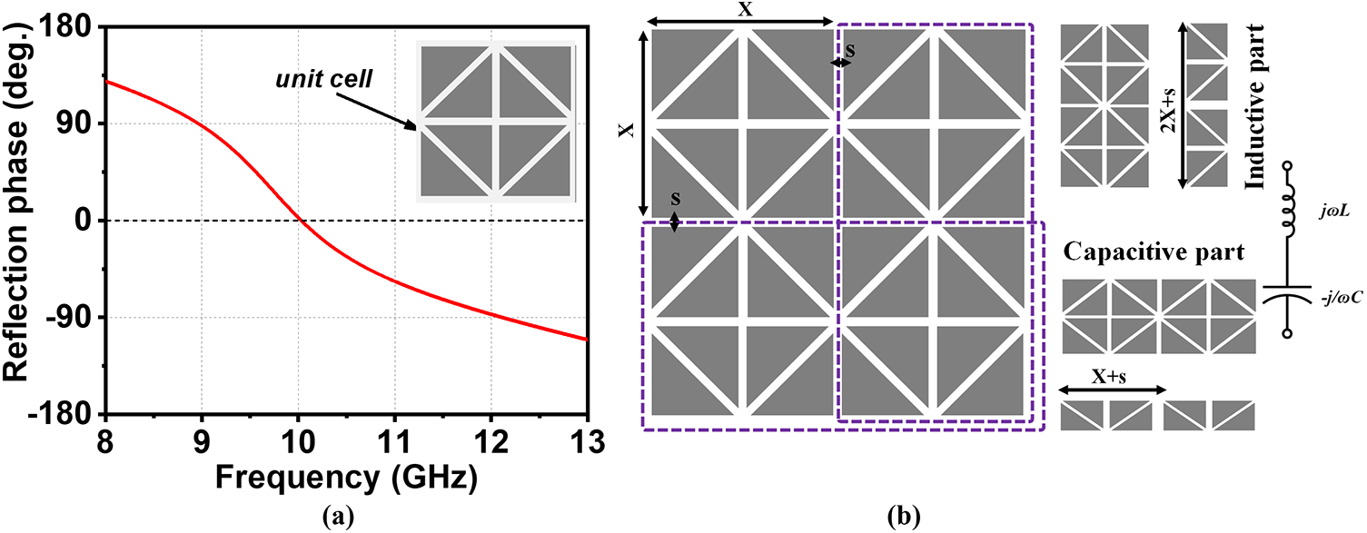
 $Z_0$ = free space impedance. According to the phase reflection properties of the unit cells of the EBG, the periodic structure functions as a reflecting surface (RS), allowing in-phase back scattering for an incident wave within a specified bandwidth. RS back scatter-phase constantly varies from
 $\pm$180 and reaches a value of “0” at a certain frequency. The resonant frequency ‘fo’ for 0
 $^{\circ}$ reflection-phase for the EBG is around 10 GHz. The wide operating band of the EBG is represented by the
 $\pm$90
 $^{\circ}$ reflection phase bandwidth, spanning from 9 to 12 GHz, as illustrated in Fig. 2(a). Moreover, the frequency characteristics of the EBG may be predicted using the equivalent circuit model, which includes capacitance and inductance. As shown in Fig. 2(b), the slotted diamond-shaped EBG may be divided into two vertical and horizontal plates. Two successive vertical plates form the inductive component, while two neighboring horizontal plates constitute the capacitive component. Consequently, the EBG may be described as a simple resonant L-C circuit. The EBG’s normalized capacitive susceptance is given by,
 \begin{equation}
\beta_{TE} = \frac{\omega}{c}\sqrt{1-\frac{(Z_{EBG})^2}{(Z_0)^2}},
\end{equation}
 \begin{equation}
L = \frac{U_{L}}{Z_{0}} = \omega \frac{L_{EBG}}{Z_{0}} = \frac{Y}{(Y+s)} F(s,2X, \lambda),
\end{equation}
 \begin{equation}
C = \frac{V_{C}}{Y_{0}} = \omega \frac{C_{EBG}\epsilon_{eff}}{Z_{0}} = \frac{4p\epsilon_{eff}}{(Y+s)} F(Y,s, \lambda),
\end{equation}
(a) Reflection phase vs frequency plot of unit cell and (b) unit cell of EBG and its equivalent circuit ( $X=7.29$ mm,
 $Y=8.19$ mm,
 $s=0.5$ mm).

here  $Z_{0}$ =
 $\frac{1}{Y_0}$,
 $\omega$ = angular frequency,
 $L_{EBG}$ and
 $C_{EBG}$ are inductance and capacitance of EBG, respectively.
 $U_{L}$ and
 $V_{C}$ are inductive reactance and capacitive susceptance, respectively [Reference Baudh, Sahu, Parihar and Kumar17].
CP DRA and its array
The single element DRA has been designed and simulated through CST Microwave suite for the analysis of its radiation characteristics. The reflection coefficient (| $S_{11}$|
 $ \lt -10$ dB) and gain vs frequency graph is displayed in Fig. 3(a) followed by the CP radiation and radiation efficiency in Fig. 3(b). It can be inferred from these plots that |
 $S_{11} \lt -10$ dB is 4.35 GHz (8.45–12.9 GHz), average gain is 8 dBic along with the radiation efficiency of 85% throughout the operating band. The 3-dB AR bandwidth falls in the range of 10.1–10.97 GHz. Further, to improve the radiation performance of the presented DRA an EBG has been employed beneath the structure and the performance corresponding to this new arrangement is depicted in the Fig. 3. It is clearly evident from the adjoining figure that gain has improved significantly. To achieve the aforementioned results, the parametric study has also been performed and the corresponding results are shown in Fig. 4(a) and (b).
Simulated results of single element: (a) reflection coefficient, radiation efficiency vs frequency plot and (b) gain and AR vs frequency plot.

Simulated results of parametric study (a, b) at various offset distance from center (c, d) at various heights of DRA.

Furthermore, the effect of DRA height on its performance has been investigated and the corresponding results have been depicted in Fig. 4(c) and (d). This study has been employed to find the optimal DRA height that shows the better performance when compared to various DRA heights. The characteristics of circularly polarized radiation [Reference Illahi, Iqbal, Ramay and Sulaiman4] in single element is evident from the rotation of electric field through the DRA at 10 GHz, as displayed in Fig. 5(a). The E-field in the DRA rotates in the anti-clockwise manner to align with the RHCP characteristics of the DRA array. The mode propagating in the DRA is  $TE_{1\delta1}$ as shown through half sinusoidal variations in Fig. 5(b). Taking into consideration the satisfactory performance of the single element, the same structure has been translated into a 1
 $\times$4 array. The layout of array has been displayed in Fig. 1(b) and (c). The linear array consists of 4 elements along the
 $x$-direction with the inter element spacing of around
 $\lambda$/2 (16mm). The optimal performance of the 1
 $\times$4 DRA array has been illustrated in Fig. 6(a) and (b). From Fig. 6, it is evident that the reflection coefficient |
 $S_{11}$|
 $ \lt -10$ dB ranges from 8.9 to 12.34 GHz while the gain and 3-dB AR bandwidth has been improved throughout the band of interest which confirms its validity as that of the single element.
(a) Electric field distribution at various phases at 10.4 GHz and (b) electric field distribution in  $xy$ and
 $xz$ planes at 9.8 GHz.

(a) Reflection coefficient vs frequency plot, (b) gain & axial ratio vs frequency plot, (c) impedance & Rad. efficiency vs frequency plot, and (d) SAR at different frequencies.

To investigate the robustness and structural deformation, the 1 $\times$4 DRA array has been conformed to the cylindrical surface at various radii of curvatures, like 100 and 50 mm and the corresponding plots of the |
 $S_{11}$|
 $ \lt -10$ dB, gain and AR bandwidth have also been displayed in Fig. 6(a) and (b) which confirms the robustness of proposed DRA array to these radii of curvatures. The significant impact has been observed on gain and ARBW, as these are the radiation characteristics of the DRA array. Fig. 6(c) shows the bending effect on the impedance matching and radiation efficiency. It is clear from Fig. 6(c), that the bending has the minimal impact on the impedance matching as it is a spectral characteristic. Fig. 6(d) displays SAR value which is calculated over 10 g body tissue at various frequencies with and without EBG. The max. value of SAR at 8.5 and 10 GHz is 1.1 and 1.05 W/kg respectively for 0.5 W input power with EBG.
Structural deformation and robustness
To validate the practical scenario, three-layer human phantom which consists of skin, fat and muscles has been created in CST Studio to mimic the real human body & their properties are listed in Fig. 7(a) [Reference Baudh, Sahu, Parihar and Kumar19]. The simulation has been performed to observe the effect of loading the DRA array on the human phantom [Reference Illahi, Iqbal, Ramay and Sulaiman4]. Fig. 7(b) and (c) displays the | $S_{11}$|
 $ \lt -10$ dB, followed by gain & ARBW when the DRA array is loaded on the human phantom for both chest and hand model.
(a) Properties of body tissues, (b) reflection coefficient vs frequency plot, and (c) gain and axial ratio in planar and conformal scenario on phantom.

Results and discussion
The prototype of the presented DRA array has been developed for experimental validation as shown in Fig. 8(a). The reflection coefficient  $|S_{11}| \lt -10$ dB in planar, bent and on body scenario of DRA array has been measured using E5071C ENA Series network analyzer and the |
 $S_{11}$| vs frequency plot is displayed in Fig. 8(a). The comparative plot of simulated and measured |
 $S_{11}$| under planar and conformal state is shown in Fig. 8(b) which confirms a coherence between the two. The ripples observed in the measured results are due to the lossy cables. The measured IBW of planar array is 34.74% (8.8–12.5 GHz). The simulated and measured gain and AR is displayed in Fig. 8(c). The gain and AR is compromised in the bending condition due to curvature effect. The measured average gain is around 10.1 dBic and ARBW is 12.2%. The radiation pattern of planar array at 9.6, 10, and 10.6 GHz in
 $xz$ and
 $yz$ planes are shown in Fig. 9(a)–(e). The DRA array is right hand circularly polarized (RHCP) and acts as co-pol. After normalization, the level of LHCP is below
 $-$19 dB in
 $xz$ plane and
 $-$22 dB in
 $yz$ plane at 10 GHz. The radiation patterns of planar and conformal array at 100 and 50 mm in phi0 and phi90 plane are displayed in Fig. 10(a) and (b). It is observed that the beam flares a little in the bent condition and is slightly tilted due to the corporate feed given to excite the DRA array. The radiation pattern in conformal state (50 mm) have also been measured. The comparison of simulated and measured radiation pattern in conformal condition is depicted in Fig. 10(c) and (d).
(a) Snapshot of prototype and measurement set-up, (b) comparison of simulated and measured reflection coefficient | $S_{11}$| at various conditions, and (c) gain and axial ratio.

Simulated and measured radiation pattern of planar array in  $xz$ and
 $yz$ plane (a, d) at 9.6 GHz, (b, e) at 10 GHz, and (c, f) at 10.6 GHz.

(a, b) Comparison of radiation patterns in planar state and bent state in phi 0 and phi 90 planes respectively, (c, d) Simulated and measured radiation pattern of conformal array (50 mm) in  $xz$ and
 $yz$ plane at 8.5 GHz, (e) beam coverage by employing 2 arrays on human phantom, and (f) 3-D radiation pattern at resonant frequency on exciting one array at a time.

The idea of beam forming is achieved by loading the human phantom with two identical DRA arrays, each of which covers a single quadrant as shown in Fig. 10(e). The 3-D radiation plots shown in Fig. 10(f) convey that antenna array 1 covers left quadrant while antenna array 2 covers the right quadrant. The total area covered by the two arrays is  $\pm$45
 $^{\circ}$. Either of the two arrays can be switched on at a time or both of them can be in the ON state depending upon the requirement.
Conclusion
A circularly polarized compact 1  $\times$ 4 DRA array has been presented which has a simple structure and is suitable for X-band defense applications. It has an EBG surface at its bottom to enhance the gain and improve the SAR in order to protect the human body from the adverse effects of back radiations. The beam forming feature can be achieved by switching the required array. The set-up is able to cover a wide range of
 $\pm$45
 $^{\circ}$.The novel yet simple design tends to reduce the complexity of staked layers to attain an impedance bandwidth of 3.35 GHz (8.9–12.3 GHz) and overlapped 3 dB ARBW of 1.23 GHz (9.48–10.72 GHz). An average gain of 10 dBic is obtained throughout the operating band. The prototype of the same has also been fabricated for the experimental validation and the simulated and measured results are found to be in good coincidence.
Competing Interests
The authors declare none.

Sonal Sahu received her B.Tech degree in Electronics and Communication Engineering from Dr. A.P.J. Abdul Kalam Technical University, Lucknow, in 2018, and her M.Tech in Digital Communication from BIET, Jhansi, in 2020. She is currently pursuing her Ph.D. in the Department of Electronics and Communication Engineering at PDPM-IIITDM, Jabalpur. Her research interests lie in RF and microwave engineering, including microstrip patch antennas, dielectric resonator antennas, wearable antennas, and antenna arrays.

Rishabh Kumar Baudh received the M.Tech. degree in Electronics and Communication Engineering from Bundelkhand Institute of Engineering and Technology (BIET), Jhansi, India, in 2019. He is currently pursuing the Ph.D. degree with PDPM Indian Institute of Information Technology, Design and Manufacturing (IIITDM), Jabalpur, India. From January 2020 to February 2022, he served as a Junior Research Fellow at IIITDM Jabalpur. His current research interests include wearable and flexible textile antennas, dielectric resonator antennas, phased array antennas, and advanced microstrip antenna design and fabrication for defense and IoT applications.

Manoj Singh Parihar received his B.Tech and M.Tech degrees from RGPV Bhopal in 2001 and 2004, respectively, and completed his Ph.D. from IIT Delhi in 2012. He served as a Sr. Project Scientist at the CARE, IIT Delhi (2010–2013). He was awarded the IETE Research Fellowship in 2007 for his work on reconfigurable antennas and received an international travel grant from NIIED and the Republic of Korea the same year. Currently, he is an Associate Professor at ABV-IIITM Gwalior. His research interests include reconfigurable antennas, microwave integrated circuits, RF MEMS, and millimeter-wave device characterization.

Dinesh Kumar Vishwakarma is a Professor of ECE at IIITDM Jabalpur, India. He earned his Ph.D. in Electrical Communication Engineering from IISc Bangalore in 2005 and was a visiting researcher in Japan from 2006 to 2009. Prior to academia, he served in the Ministry of Communication & IT through the Indian Engineering Services (IES). His research focuses on computational electromagnetics, microwave circuits, antennas, wave propagation, photonics, and optical communication. He has authored numerous publications, led sponsored projects, and is a member of the IEEE Antennas and Propagation, Communications, and Photonics Societies.