Introduction
The channel capacity of the multiple-input-multiple-output (MIMO) antenna is increased due to the transmitter radiating the identical power and the receiver receiving it, and hence, there is no necessity for additional bandwidth [Reference Hadda, Sharma, Gupta, Kumar and Singh1]. This type of multiple radiating antennae suffers one major drawback which is maintaining isolation between the neighboring radiators which are closely packed. There can be different configurations of the MIMO antenna (2 × 2, 4 × 4) [Reference Hadda, Sharma, Gupta, Kumar and Singh1–Reference Malaisamy, Santhi and Robinson35] which are designed for specific applications and ensure good isolation between them. The MIMO antennas [Reference Hadda, Sharma, Gupta, Kumar and Singh1–Reference Addepalli and Anitha20] discuss the design methodology and isolation techniques used so that the interference between the neighboring radiators' field radiation is mitigated and hence, all the required results are preserved. A square patch with rectangular ground placed orthogonally maintains isolation of more than 30 dB [Reference Hadda, Sharma, Gupta, Kumar and Singh1] while a T-type stub attached to the ground between two adjacent radiators [Reference Chandel and Gautam2, Reference Chandel, Gautam and Rambabu3, Reference Pannu and Sharma12] and a tapered feed patch MIMO antenna [Reference Chandel, Gautam and Rambabu4, Reference Liu, Cheung and Yuk8] observes better isolation by using rotated L-type strips. A funnel-shaped stub placed between shared ground [Reference Gautam, Yadav and Rambabu5], a rectangular-rotated L-type strip in the ground between two orthogonal radiating patches [Reference Liu, Cheung and Yuk6], and an etching pair of symmetrically-cut rectangular slots are the other reported techniques to achieve better isolation [Reference Liu, Cheung and Yuk7]. In an F-shape inverted antenna, a Swastik-shaped repetitive etched structure is applied to improve the isolation [Reference Kaur and Singh9], and a short stub-loaded resonator with added T-shaped junction in between dual radiating patch [Reference Dkiouak, Zakriti, El Ouahabi and McHbal10] and novel elliptical type stub in-ground helps in achieving higher [Reference Khan and Khattak11]. A unique pair of fractal stub [Reference Bhattacharjee, Karmakar, Saha and Bhattacharya13, Reference Sohi and Kaur15, Reference Xu, Wen and Dong16] multiband MIMO antenna with a T-shaped stub on the ground [Reference Biswas, Swarnakar, Pattanayak and Chakraborty14] and the dual half-cut quasi self-complementary MIMO antenna utilizes no complex decoupling structure for isolation [Reference Kaur, Singh and Upadhyay17]; feather-type circular-shaped loaded radiator achieves isolation by placing the two identical radiators orthogonally or adjacent to each other [Reference Singhal18, Reference Vyas and Yadav19] and a T-type stub etched with semicircular slot also helps in maintaining higher isolation between two radiating elements placed adjacent to each other [Reference Addepalli and Anitha20]. The above-discussed MIMO antenna is of 2 × 2 configuration and also different techniques are applied to achieve better isolation in a four-port MIMO configuration. A four-semielliptical MIMO antenna with an asymmetric coplanar strip placed in an orthogonal fashion occupying a size of 48 × 52 mm2 on an FR4 substrate requires no additional isolation element [Reference Ibrahim and Ali21]. A MIMO antenna for automative application which is interlocked with a four-radiating patch achieves higher isolation in a bandwidth of 2.80–9.50 GHz [Reference Saravanan, Kalidoss, Partibane and Vishvaksenan22]. Radiation pattern and polarization diversity are achieved in four pairs of microstrip fed antenna which also consists of dual-concentric annular slots [Reference Sghaier and Latrach23, Reference Deng24] and five concentric stubs placed between four radiators [Reference McHbal, Amar Touhami, Elftouh and Dkiouak25]; a defected ground structure monopole of 4 × 4 configuration uses no isolation element as the inter-spacing between them achieves higher isolation [Reference Hasan, Chu and Bashir26] and by maintaining the spacing of <0.05λ between radiators isolation of more than 16 dB is achieved [Reference Karimian, Soleimani and Hashemi27]. Three MIMO antenna configurations [Reference Sharma, Vashist, Ashtankar and Mittal28–Reference Dhasarathan, Nguyen, Sharma, Patel, Mittal and Pandian30, Reference Rajkumar, Amala and Selvan32, Reference Khan, Iftikhar, Shubair, Capobianco, Braaten and Anagnostou33] with four radiating patches utilize no decoupling structures and a fan-shaped parasitic structure between the four-radiating patch achieves better isolation [Reference Hassan, Rasool, Asghar and Zahid31]. A three-layered MIMO antenna offers high diversity performance with isolation <−20 dB [Reference Eslami, Nourinia, Ghobadi and Shokri34] and four square-patch placed exactly at the center of the edges with defected ground records isolation of <−37.50 dB in the operating band of interest [Reference Malaisamy, Santhi and Robinson35].
This paper reports a 4 × 4 MIMO antenna configuration designed for 5G-NR bands applications which include n77, n78, and n79. The reported design consists of a Calendula-shaped radiating patch which is fed asymmetric using a microstrip. The four-radiating patch which also consists of respective rectangular etched ground and an attached rectangular provides good impedance matching and interconnected ground with strip results in higher isolation between them, thereby providing a better platform for diversity performance. The MIMO design is carried out by first designing a single radiating antenna and then modifying the same to the MIMO configuration which is discussed below.
Proposed antenna configuration and antenna evolution (single radiating patch)
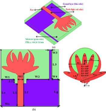
This research discusses the evolution of the proposed single-element antenna which is modified to work with a four-port configuration and mitigates all the demerits possessed by a single radiating patch. Figure 1 shows the complete configuration of the proposed unit element antenna with a radiating patch resembling Calendula flower and rectangular ground etched with the rectangular slot. Figure 1(a) shows the perspective view of the antenna is fabricated on an FR4 substrate for the design of the proposed antenna. Figure 1(b) shows the detailed dimensions which are optimized by using an EM simulator. Also, it can be observed that the radiating patch is fed by an asymmetric 50 Ω microstrip line. The partial rectangular ground which is printed on the opposite plane of the substrate is etched with a rectangular slot behind the microstrip line. Figure 1(c) represents the detailing of the Calendula flower leaves and these leaves are aligned at different angles concerning origin (E1 = 165°, E2 = 015°, E3 = 90°, E4 = 105°, and E5 = 70° (anticlockwise direction)). All the optimized dimensions shown in Fig. 1 are recorded in Table 1 given below.
Proposed 5G-NR antenna design with single radiation patch; (a) perspective view, (b) front view with a magnified patch.

Proposed single and four-element 5G radiators parameter with values

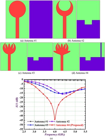
The next step is to study the evolution of the proposed antenna which is shown in Fig. 2. Figure 2(a) depicts a circular patch antenna with the ground on the opposite plane containing the patch. This antenna #1 exhibits very poor matching of the impedance as observed in Fig. 2(e). The improvement of the impedance is noted by modifying antenna #1 to antenna #2 where the circular patch is etched by a circular slot and the partial ground is etched with a rectangular slot which is shown in Fig. 2(b). This modification improves the matching of impedance and the partial 5G NR bands are achieved. Further antenna #3 shows the addition of three fractal leaves with the patch connected to asymmetric feed. The lower bandwidth is improved when compared with the previous version. The final version of the antenna shown in Fig. 2(d) which is antenna #4 achieves all the 5G NR bands including n77, n78, and n79 which is the objective of the design. The modification includes the addition of two more cornered leaves and a rectangular stub attached to the ground providing an impedance bandwidth of 3.18–5.53 GHz.
Evolution of the antenna (a) Antenna #1 (b) Antenna #2 (c) Antenna #3 (d) Antenna #4 (e) S11 result of Antenna#1–Antenna#4.

Study of key parameters affecting the bandwidth and surface current distribution
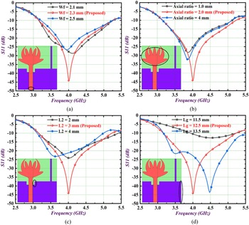
The proposed single-element antenna discussed in section “Proposed antenna configuration and antenna evolution (single radiating patch)” was the optimized version shown in Fig. 1. However, the key parameters which are optimized including Wf, axial ratio, L2, and Lg offer a vital role in the matching of the impedance and designing of the antenna, thus, change in their respective physical length does affect the operating bandwidth to a larger extent. These effects are seen by studying the parametric study shown in Fig. 3. The width of the microstrip, Wf is calculated by following equations


Parametric analysis on; (a) feed width (Wf), (b) axial ratio (A.R), (c) truncated ground slot length (L2), (d) truncated ground length (Lg).

Here Zo is the impedance (Ω), Wf is the width of microstrip (mm), t is the trace width (mm), h is the height of the dielectric material used in this design, ɛr is the permittivity of the microwave substrate used.
As per the observations from Fig. 3(a), the width of the microstrip line changes the impedance of the feed which is governed by three equations, equations (1)–(3). The impedance of the feed line is designed for 50 Ω and the variation of width Wf also changes the impedance which in turn affects the overall impedance of the antenna. The values for Wf are changed from 2.10 to 2.50 mm, achieving the required bandwidth, but more matched impedance is observed for Wf = 2.30 mm with S11 = −44.86 dB at 4.00 GHz. Similarly, the partial ellipse used in the design with axial ratio = 2.0 shown in Fig. 3(b) also provides the required impedance bandwidth of 3.18–5.51 GHz with corresponding S11 = −44.86 dB at 4.00 GHz. The variation of L2 which is the height of the etched rectangular slot on the ground observes a larger deviation of the S11 parameter recorded in Fig. 3(c). For L2 = 3.00 mm which is an optimized value that achieves the 5G NR bands. Another important parameter Lg, which is the length of the ground, observes very poor matching of impedance for Lg = 11.50 mm and deviation of center resonance frequency to 4.48 GHz for Lg = 13.50 mm. After optimization, for Lg = 12.50 mm, the impedance bandwidth covers n77, n78, and n79 bands with S11 = −44.86 dB at 4.00 GHz.
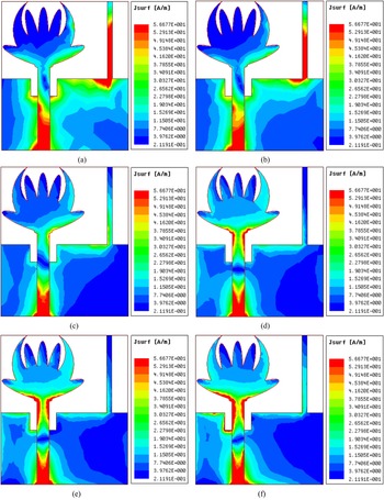
The illustration of the surface current density at 3.30, 3.50, 4.00, 4.50, 4.80, and 5.00 GHz is shown in Fig. 4. Figures 4(a) and 4(b) show the distribution of surface current for 3.30, 3.50, and 4.00 GHz which covers the n77 and n78 bands. From the observations, the electric current is strongly distributed on the portion of microstrip and rectangular stub attached to the ground and confirms that these three-antenna areas form part of the radiating structure. It can also be depicted from Fig. 3(d) that the length of the ground does affect the matching of the impedance. Figures 4(d)–4(f) show the simulated current density distribution for 4.50, 4.80, and 5.00 GHz respectively for the n79 band. The same observations are noted that the surface current density is maximum within the feedline. For the remaining area of the antenna structure, the distribution of surface current is maximum, thereby ensuring all the input signals are radiated.
Surface current distribution of 5G single radiator at various frequencies; (a) at 3.30 GHz, (b) at 3.50 GHz, (c) at 4.00 GHz, (d) at 4.50 GHz, (e) at 4.80 GHz, (f) at 5.00 GHz.

Modified 4 × 4 MIMO antenna (without and with stub)
The high throughput in the limited bandwidth environment is solved in multiple antenna configurations or MIMO systems. The demand for the faster transmission of higher data concerning time lead to the evolution of the MIMO antenna maintaining enhanced bandwidth/throughput of the data under different conditions including interference, fading of the signal, and multipath followed by signal at the receiver side. It is known from the Shannon–Hartley theorem [Reference Shannon36] that the capacity of the channel is given by

where C is the channel capacity, BW is the bandwidth, and SNR is a signal-to-noise ratio.
From above equation (4), it can be concluded that the channel capacity can be increased by increasing more number of radiating antennas rather than a single one. A MIMO channel capacity is calculated by

Equation (5) suggests that increasing the number of radiating elements rather than increasing channel SNR which ends up in marginal gains increases the channel bandwidth and hence higher throughput is achieved.
Based on the above concept, a 4 × 4 MIMO antenna configuration is developed which is the modified version of the single radiating antenna discussed in previous sections. All the key results corresponding to MIMO configuration including bandwidth, diversity performance, and far-field results are discussed below.
Figures 5(a)–5(d) show the design of the 4 × 4 MIMO antenna which is the modified version of the antenna shown in Fig. 1.
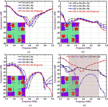
Parametric analysis on substrate of isolated ground; (a) S11 values, (b) S21 or S41 values, (c) S31 values, (d) S-parameters of 60 × 60 mm2 size 5G radiator with isolated ground.

Figure 5(a) shows the reflection coefficient (S11 in dB) curves with a 4 × 4 MIMO antenna configuration. The unit cell or single radiating antenna is placed in orthogonal sequence with their respective ground to achieve spatial diversity. Figure 5(a) shows the simulated S11 curves for different sizes of the antenna (54 × 54, 56 × 56, 58 × 58, and 60 × 60 mm2). The optimized size of the antenna with 60 × 60 mm2 achieves the required 5G bands and also the center frequency. It is worth noting that there is no decoupling structure used, but Fig. 5(b) which shows the transmission coefficient curve between port 1-port 2 and port 1-port 4 observes poor isolation between them due to the reason that they are placed adjacently. Figure 5(c) which shows the isolation graph (S31 in dB) between port 1-port 3 records better values of isolation in the operating band suggesting that these two radiating patches are not adjacent but are diagonally placed in an orthogonal fashion. Also, the proposed antenna as observed in Fig. 5(c) shows better S13 results. Figure 5(d) compares the reflection and transmission coefficients of port 1 concerning port 2, port3, and port 4. The required bandwidth for 5G bands is achieved but the matching of impedance is poor and can be further improved when a decoupling structure is used. Also, the S31 shows good isolation, but S21 and S41 offer poor isolation between them and need to be improved.
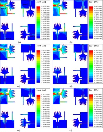
Figure 6 shows the distribution of surface current density for a four-element 5G radiator with the isolated ground for frequencies 3.30, 3.50, 4.00, 4.50, 4.80, and 5.00 GHz. This simulation is obtained by exciting port 1 and matching all the remaining ports (port 2, port 3, and port 4) with the matched impedance of 50 Ω. As per the observations from all the six figures shown in Fig. 6 for different frequencies, it can be observed that the interference between the adjacent radiating antennas is more while the antenna placed diagonally has less interference which is already shown in Figs 5(c) and 5(d). The above-discussed results for MIMO antenna will not result in very good diversity performance, and hence further modification or addition of decoupling structure becomes necessary.
Surface current distribution of four-element 5G radiator isolated ground at various frequencies when port 1 is excited; (a) at 3.30 GHz, (b) at 3.50 GHz, (c) at 4.00 GHz, (d) at 4.50 GHz, (e) at 4.80 GHz, (f) at 5.00 GHz.

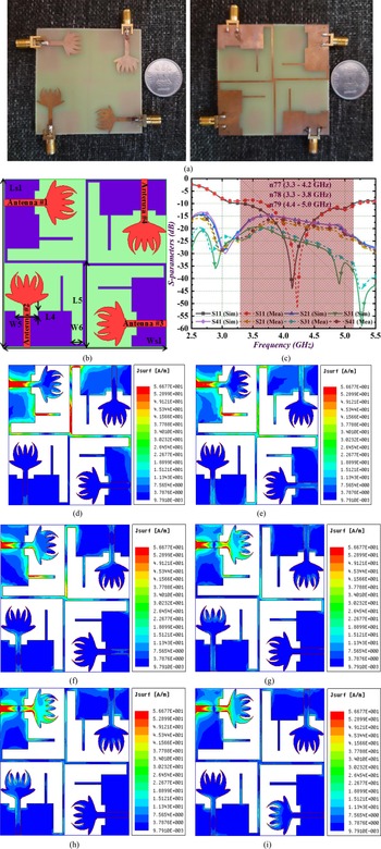
The 4 × 4 MIMO antenna discussed in Fig. 5 inherits demerits such as poor isolation and hence poor diversity performance. This problem is overcome in the proposed 4 × 4 MIMO antenna configuration shown in Fig. 7. Figure 7(a) shows the prototype of the proposed 4 × 4 MIMO antenna configuration with a decoupling structure connected to all the grounds. The modification of the MIMO antenna ensures better isolation between all the ports which was not available in the earlier proposed MIMO design. The rectangular strip which is interconnected with the ground as shown in Fig. 7(b) ensures good impedance matching for the desired n77, n78, and n79 bands as shown in Fig. 7(d). It can be observed that the simulated S11 parameter offers the maximum value of −44.68 dB at 4.18 GHz, while the measured values are −50.28 dB at 4.52 GHz. In both the simulated and measured results comparison, the MIMO antenna covers all the 5G bands. Similarly, the proposed MIMO antenna also offers better isolation of more than −15 dB for both simulated and measured results.
(a) Prototype of 4 × 4 MIMO antenna with decoupling structure; (b) simulation snapshot; (c) simulated and measured S-parameters; (d)–(i) surface current density distribution at 3.30, 3.50, 4.00, 4.50, 4.80, and 5.00 GHz.

Figures 7(d)–7(i) show the distribution of surface current for 3.30, 3.50, 4.00, 4.50, 4.80, and 5.00 GHz. Port 1 corresponding to antenna #1 is excited while all the remaining ports (port 2, port 3, and port 4) are terminated with a matched impedance of 50 Ω. The transmission coefficients shown in Fig. 7(c) offer isolation of more than −15 dB and this is due to the reason that the additional decoupling structure used in the ground provides an additional path for the flow of current and hence prevents the interaction between all the remaining radiating antennas, thereby reducing the interference which was observed for MIMO antenna without decoupling structure.
Diversity performance
There are different diversity schemes such as space diversity, frequency diversity, angle diversity, time and multiple path diversity, and polarization diversity. The fading of the two signals will differ when two or more radiating antennas are separated by a minimum distance of 0.5λo (where λo is the operating wavelength corresponding to the frequency of 4.00 GHz in the proposed 4 × 4 MIMO antenna configuration (Table 2).
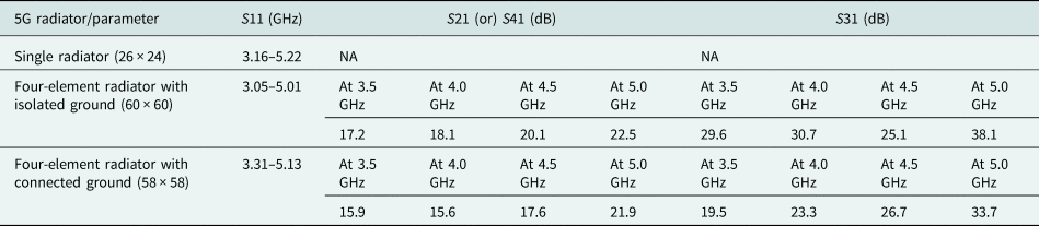
Comparison of S11, S21 (or) S41, and S31 of 5G radiators

Envelope correlation coefficient (ECC) which is a very important parameter of diversity performance is calculated by using either a far-field radiation pattern or using scattering-parameter. Calculation of ECC from S-parameter makes assumptions that all the signals which are fed to the antenna are uniform spread, as well as all the radiation elements are well matched and possess no loss. The following equations show the calculation of ECC using radiation patterns concerning fields radiated and S-parameter (2 × 2 and 4 × 4 MIMO) [Reference Chandel, Gautam and Rambabu3, Reference Karimian, Soleimani and Hashemi27]


For the four-port MIMO antenna configuration, ECC is evaluated by
 $$ECC_{m \times n} = \displaystyle{{{\vert {S_{11}^\ast \;S_{12} + S_{12}^\ast \;S_{22} + S_{13}^\ast \;S_{32} + S_{14}^\ast \;S_{42}} \vert }^2} \over { {( {1-( {{\vert {S_{11}} \vert }^2 + {\vert {S_{21}} \vert }^2 + {\vert {S_{31}} \vert }^2 + {\vert {S_{41}} \vert }^2} } ) } ) {( {1-( {{\vert {S_{12}} \vert }^2 + {\vert {S_{22}} \vert }^2 + {\vert {S_{32}} \vert }^2 + {\vert {S_{42}} \vert }^2} } ) } ) }}.$$
In equation (6), Fm and Fn have radiated fields of the mth and nth antennas. For the ideal MIMO array, the ECC is zero, but for practical cases, these values are expected to be <0.50.
The effective diversity in the communication channel is given by the diversity gain which shows the dissimilarity between the time-average SNR signals. This compares the diversity of several radiating antennae when compared with the single antenna system. The DG which is evaluated by equation (9) is related to ECC as given by

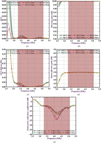
The values of directive gain (DG) should be ideally 10 dB, and in the proposed antenna, these values are approximately 10 dB as noted in Fig. 8(b).
Diversity performance; (a) ECC4×4 (simulated and measured), (b) DG4×4 (simulated and measured), (c) CCL4×4 (simulated and measured), (d) MEG4×4 (simulated and measured), (e) TARC4×4 (simulated and measured).

The capacity of the channel signifies the efficient transmission of the signal with no distortion or loss of data bits in the communication environment. However, the ideal condition is not achieved, and hence channel capacity loss (CCL) has to be evaluated which is given by the following equations

where


The maximum allowable CCL values or ideally CCL < 0.40 b/s/Hz and in the proposed 4 × 4 MIMO antenna configuration, the values of CCL are 0.04 b/s/Hz which are better than 10 times the ideal values as observed in Fig. 8(c).
The antenna receiving averaged signal is computed by the diversity parameter known as mean effective gain (MEG) and is defined as the ratio of the power received by the receiving antenna to the total power which is incident on it. The MEGs are calculated between any two antennas by generalized formula given for the mth and nth antenna


The ratio calculates the MEG which is given by

For the proposed antenna, MEGs calculated for antenna #1-antenna #2, antenna #1-antenna #3, and antenna #1-antenna #4 were simulated and measured values are plotted in Fig. 8(d). As per the observations, the ratio of MEG values is approximately −3.0 dB for both simulated and measured values.
In MIMO antenna configuration, the radiating elements are closely placed to each other and are operated at the same time, but this arrangement of radiating antennas also affects the performance in terms of interference. This suggests that the S-parameters obtained for the MIMO antenna only do not ensure the merit of interference, and hence a new parameter called total-active-reflection-coefficient (TARC) needs to be evaluated. This parameter is defined as the “square root of the ratio of total reflected power to the total incident power and overall apparent loss”. The TARC between any two ports is calculated by


Figure 8(e) shows the simulated and measured TARC values which are below −10 dB in all the three bands of 5G and the expected values are <0 dB indicating more power is incident rather than reflected and this is due to the highly achieved matched impedance in the proposed design.
Discussion of results and comparison with other state-of-the-art designs
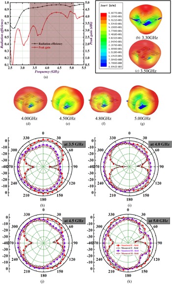
This section discusses the far-field result characterization of the proposed antenna. Figure 9(a) shows the radiation efficiency and measured peak gain (dB) of the proposed antenna. The MIMO antenna offers a radiation efficiency of 0.9 on the normalized scale which is more than 90% in the operating 5G bands. Also, the variation of the peak gain is between 2.50 and 4.50 dBi. Figures 9(b)–9(g) show the 3D radiation pattern which is simulated for 3.50, 4.00, 4.50, 4.80, 3.30, and 5.00 GHz. The 3D radiation pattern shows the capability of the MIMO antenna to maintain desired donut pattern in E- and omni-directional pattern in the H-plane. Figures 9(h)–9(k) show the 2D radiation pattern of the proposed antenna at 3.50, 4.00, 4.50, and 5.00 GHz which shows that all the three 5G bands (n77, n78, and n79) antenna offers dipole-type pattern and omni-directional pattern in both principal planes.
Far-field result discussion; (a) radiation efficiency and peak gain, (b)–(g) 3D radiation pattern, (h)–(k) 2D radiation pattern.

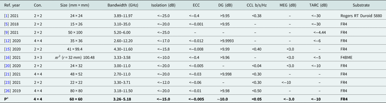
This section also discusses the comparison of the proposed antenna with the present state-of-the-art design which is compared with previously published work and is tabulated in Table 3. It can be observed that the proposed MIMO antenna configuration designed for n77, n78, and n79 5G bands occupies a substantial area of 3364 mm2 and also utilizes FR4 substrate which makes it a more prominent candidate to be integrated with microwave integrated circuits (MICs) circuits. The comparison table also suggests that the proposed antenna offers very good diversity performance. This novel design of the MIMO antenna makes it more suitable for different handheld devices intended for 5G applications.
Comparison of the proposed work with the latest reported articles

a P (proposed antenna).
Conclusions
In this research article, a 4 × 4 MIMO antenna is proposed where a rectangular stub is used in the ground to achieve isolation and this technique does not only affect the working bandwidth. The Calendula radiating patch which forms the asymmetric fed MIMO antenna configuration offers good diversity performance with ECC < 0.005, DG ~ 10 dB, CCL < 0.05 b/s/Hz, MEG ≈ −3.0 dB, and TARC < −10 dB. The proposed antenna maintains a radiation efficiency of more than 90% and gain between 2.50 and 4.50 dBi. The MIMO antenna is compared with simulated and measured 2D radiation patterns offering excellent dipole-like and omni-directional patterns and desired radiation planes. All the above excellent characteristics offered by the proposed MIMO antenna make it a suitable candidate for the integration with applications including n77, n78, and n79 bands.
Conflict of interest
None.
 Dr. Tathababu Addepalli was born in 1986, AP, India. He received his B.Tech. degree from JNTUH, Hyderabad in 2007, M.Tech. degree from JNTUK, Kakinada in 2010, and Ph.D. degree from JNTUA, Anantapur in 2022. Currently, he is working as Associate Professor in the department of ECE at Aditya Engineering College (A), Surampalem, Kakinada, Andhra Pradesh. He has published 10 SCIE research papers in various reputed international journals like Elsevier (International Journal of Electronics and Communications (AEU)), Wiley (International Journal of Communication Systems (IJCS)), MDPI (Electronics), Springer (Wireless Personal Communications (WPC)), Wiley (Transaction on Emerging Telecommunication Technologies (ETT)), Elsevier (Alexandria Engineering Journal (AEJ)), and Taylor & Francis (Journal of Electromagnetic Waves and Applications), presented five conferences (four IEEE, one Springer), published two book chapters on THz antennas and planar antennas. He attended more than 40 workshops in various reputed institutions. His areas of interest are microstrip patch antennas, MIMO antennas, 5G antennas, flexible antennas, characteristic mode analysis (CMA), THz antennas, and metamaterial antennas.
 Dr. Thota Vidyavathi received her B.Tech. degree from JNTU Hyderabad in the Department of Electronics and Communication Engineering during the year 2006 and the Master of Technology in Radar and Microwave Engineering from Andhra University College of Engineering (A) in the year 2008. Her Ph.D. degree was awarded in the year 2015 from the Department of ECE, Andhra University. Currently, she is working as an Assistant Professor in the Department of ECE, Gayatri Vidya Parishad College of Engineering (A), Visakhapatnam, Andhra Pradesh, India. Her research interests include array antennas, electromagnetic theory and wave propagation, radar engineering, microwave engineering, EMI/EMC, computational electromagnetics, and soft computing. She has guided more than 20 UG and PG projects. She is a member of IEEE antennas and Propagation Society; she is life member of Society of EMC Engineers, SEMCE (India) also a member of International Association of Engineers (IAENG) and International Association of Academic plus corporate (IAAC). She is a Fellow member of IETE. She is recipient of Young Scientist Award-March 2020 and Young Women Researcher Award-February 2022. Presently she is working in the area of array antennas design by using HFSS software simulation. She has three patents and published in various reputed national and international journals. She is paper reviewer for various Scopus and SCI indexed journals. She has organized and coordinated various international conferences, technical workshops, faculty development programs, and given guest lectures in the department.
 Neelima Koppala received her M.Tech. degree in Embedded Systems from JNTUA Anantapur in 2015, and is now currently working as an Assistant Professor in ECE Department, Sree Vidyanikethan Engineering College, Tirupati. She has published more than five peer-reviewed journals and presented conferences in various reputed institutions. Her current research interests include MIMO antennas, reconfigurable antennas, information theory, VLSI, and image processing.
 Dr. Manish Sharma received B.E. degree in Electronics and Communication Engineering from Mangalore University, Karnataka, India in 2000 and M.Tech. degree from Visvesvaraya Technological University, Karnataka, India in 2007. He completed his Ph.D. degree from the Department of Electronics Engineering, Banasthali University, Rajasthan, India in 2017. He is currently working as a Professor-Research in Chitkara University Research and Innovation Network (CURIN), Chitkara University, Punjab, India. His research interest includes computational electromagnetics, reconfigurable antennas, novel electromagnetic materials, dielectric resonator antennas, wideband/superwideband antennas, wideband/dual band/triple band microstrip antennas for wireless communication, smart and MIMO antennas systems, radio-frequency identification (RFID) antennas, antennas for healthcare, RF MEMS planar antenna on Si substrate, wireless networks, body area networks, meta surface-based biosensors, designing of microstrip antennas using machine learning and artificial network. He has published more than 100+ research articles in SCI/SCOPUS Indexed journals and also granted three patents. He has guided two Ph.D. students and currently there are eight ongoing Ph.D. scholars.
 Dr. Dheeraj Kumar received M.Sc. and Ph.D. degrees in Physics. He is currently an Assistant Professor in the Department of Physics and Electronics, Rajdhani College (University of Delhi), Delhi. He has published several scientific papers in the field of microstrip antenna. His research interests include MIMO, 5G antenna system, and terahertz antenna.