Nomenclature
- A
-
amplitude
- c
-
chord
-
 ${c_t}$
-
thrust specific fuel consumption
- CFD
-
computational fluid dynamics
-
${C_D}$
-
drag coefficient
-
${C_{Di}}$
-
induced drag coefficient
-
${C_{D0}}$
-
zero-lift drag coefficient
-
${C_L}$
-
lift coefficient
-
${C_{Mr}}$
-
root bending moment coefficient
-
${C_p}$
-
pressure coefficient
-
${E_i}$
-
endurance
- k
-
induced drag constant
-
$L/D$
-
lift-to-drag ratio
- p
-
static pressure
-
${p_\infty }$
-
freestream static pressure
-
${q_\infty }$
-
freestream dynamic pressure
-
${R_i}$
-
range
- RANS
-
Reynolds averaged Navier-Stokes
- S
-
wing surface
- WLE
-
wavy leading edge
-
${W_i}$
-
aircraft weight in mission segments


Greek symbol
-
$\alpha $
-
angle-of-attack
-
${\eta _p}$
-
propeller efficiency
-
$\lambda $
-
wavelength
-
$\rho $
-
density


1.0 Introduction
A wavy leading edge (WLE) mimics the protuberances found on the humpback whale pectoral flippers with a sinusoidal function. [Reference Fish and Battle1] showed that tubercles, which are thought to prevent severe losses of lift (or stall) at high angles of attack, provide humpback whales remarkable manoeuverability during predation. For this reason, in an engineering context, tubercles have been widely studied as a passive flow control technique to control the base pressure and optimise the drag force of several devices. Numerous experiments and computational analyses have been conducted to better understand the stall-delay mechanism and flow properties of tubercles [Reference Yoon, Hung, Jung and Kim2–Reference Skillen, Revell, Pinelli, Piomelli and Favier5].
Given this potential, tubercles on the leading edges of aero- and hydro-dynamic configurations have been the focus of much research over the past decades, with many of these investigations focusing on the design of aircraft, watercraft and windmills [Reference Gopinathan and Rose6]. For example, when implemented on wings, the aerofoil with WLE has better post-stall characteristic and worse pre-stall performance than a smooth aerofoil. Whereas the pressure varies mainly in the chord-wise direction over a smooth leading edge wing, the WLE geometry accentuates the pressure gradients at its valleys and peaks (see Fig. 1), thus resulting into a greater span-wise pressure variation nearby the leading edge [Reference Custodio, Henoch and Johari7].
Wavy leading edge geometry and aerofoil modification.

Furthermore, the leading-edge separation originates primarily from the protuberance valleys in pre-stall region, and attached flow occurs on the protuberance peaks in post-stall region [Reference Miklosovic, Murray, Howle and Fish8, Reference Miklosovic, Murray and Howle9]. In other words, as the angle-of-attack (
 $\alpha $
) is increased, low pressure cells are formed behind the WLE valleys, and they enlarge towards the trailing edge for higher angles of attack. The low pressure cells keep emerging behind the valleys and, despite becoming smaller and dissipate more easily, they turn stall gradual instead of abrupt, which increases lift after the stall angle-of-attack [Reference Weber, Howle, Murray and Miklosovic10–Reference Esmaeili, Delgado and Sousa12]. In addition, due to the pressure difference between the peaks and valleys, counter-rotating vortices are generated at each side of the peaks. These vortices energise the flow, increase its consistency, and retain the flow attached behind the valleys [Reference Custodio13, Reference Zhao, Zhao and Liu14]. Such vortices also reduce the span-wise flow, performing as passive wing fences to improve aerodynamic performance [Reference Hansen, Kelso and Dally15, Reference Cai, Zuo, Morimoto, Maeda, Kamada and Liu16].
The WLE aerodynamic effects are determined by its governing parameters: amplitude (A) and wavelength (
 $\lambda $
). Amplitude increment enhances lift in the post-stall regime, but reduces both the maximum lift coefficient and the lift slope slightly. In contrast, a wavelength reduction provides a more prominent control effect on the flow separation [Reference Malipeddi, Mahmoudnejad and Hoffmann17]. The amplitude may be defined as the main parameter since the optimum wavelength seems to depend on it [Reference Chen, Qiao and Wei18, Reference Mehraban, Djavareshkian, Sayegh, Feshalami, Azargoon, Zaree and Hassanalian19]. In addition, amplitude modulation by the superposition of an additional wave function has been presented as a viable option to prevent the lift slope and maximum lift coefficient decrements [Reference Seyhan, Sarioglu and Akansu20]. In this context, some studies have focused on practical applications of the WLE in diverse fields of the aeronautical industry. Bolzon et al. [Reference Bolzon, Kelso and Arjomandi21] examined the vorticity behind a swept wing, showing that its fence effect increases the local circulation along the wing span, which reduces flow accumulation towards the wing tip, directly affecting the wing tip vortex intensity. Furthermore, previous works [Reference de Paula, Rios Cruz, Ferreira, Kleine and da Silva22–Reference Papadopoulos, Katsiadramis and Yakinthos25] have studied the role of WLE by varying the amplitude and wavelength on the aerodynamic performance of swept wings. The results show that there is a noticeable potential on controlling the flow on the wings, which can lead to an aerodynamic performance and efficiency increase.
Despite plenty of research on WLE, its aerodynamic benefits on lifting surfaces seems to be limited to high
 $\alpha $
ranges. Therefore, the key innovation of this paper is the application of WLE as a biomimetic approach to enhance winglet aerodynamic performance. Winglets are well-known wingtip devices that increase wing performance at high
 $\alpha $
. They can reduce the induced drag component by
 $20\% $
and increase the aerodynamic efficiency by
 $9\% $
under certain flight conditions [Reference Céron-Muñoz, Cosin, Coimbra, Correa and Catalano26]. In this context, our hypothesis states that improving aerodynamic efficiency and reducing wingtip vortex circulation can be achieved by implementing leading edge protuberances on winglets. Towards this end, the primary contribution of this paper is an application of computational fluid dynamics (CFD) simulations based on Reynolds-averaged Navier-Stokes (RANS) equations and wind tunnel experiments to calculate the aerodynamic characteristics, with three main objectives:
-
1. To determine if a low-induced drag can be achieved by implementing WLE on a particular winglet configuration.
-
2. To investigate the aerodynamic effect that is associated with the chosen sinusoidal (tubercle) leading-edge (amplitude and wavelength) on the wingtip vortex.
-
3. To provide an estimate for the performance improvement offered by the winglet with WLE on a simulated real condition.
With regard to the third objective, an agricultural aircraft served as a baseline for performance comparison. This configuration has been previously designed with a multi-winglet device that provides significant increase in lift coefficient and allows each element to influence the flow pattern due to the preceding elements. As a result, the vortex dissipates much further upstream than it would with alternative winglet arrangements [Reference Bravo-Mosquera, Cerón-Muñoz, Daz-Vázquez and Catalano27]. Thus, a back-to-back comparison between such bioinspired wingtip devices (i.e. WLE winglet and multi-winglet) on the basis of an agricultural aircraft mission is presented. In this way, the present study will aim to provide an understanding of how well the WLE winglet configuration can perform in the agricultural aircraft category when compared to other devices already studied.
The paper is organised as follows. Section 2 provides an overview of the geometrical parameters of the winglet with WLE. Section 3 introduces the agricultural aircraft along with its design requirements and main dimensions. Section 4 describes the aerodynamic methodology implemented to evaluate the models, which include CFD simulations and wind tunnel experiments. Section 5 presents and discuss the results, while conclusions are presented in Section 6.
2.0 WLE and winglets design
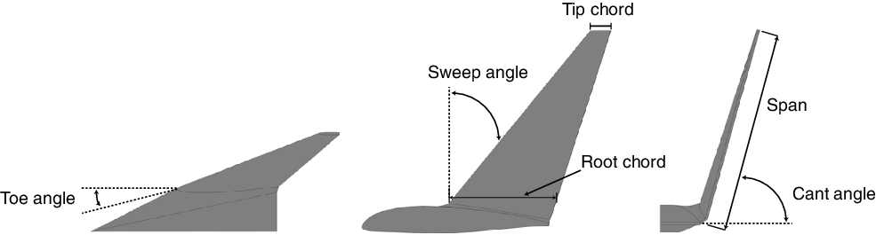
Winglets were designed for low-speed aircraft based on Maughmer’s theory [Reference Maughmer, Swan and Willits28]. Test models are composed of a rectangular wing section, a transition section between the rectangular section and the winglets, a baseline winglet with smooth leading edge, and a winglet with WLE. The NACA 23015 aerofoil is used as a main cross section for the rectangular wing, which provides high lift with a minimum pitching moment [Reference Bravo-Mosquera, Cerón-Muñoz, Daz-Vázquez and Catalano27]. The winglets share the same aerofoil throughout the span, in this case, the NACA 0008 aerofoil was chosen because its performance characteristics are well researched and understood. The cant, sweep and toe angles are
 ${75^ \circ }$
,
 ${38^ \circ }$
and
 ${4^ \circ }$
, respectively. The winglet parameters are depicted in Fig. 2.
The WLE was generated by displacing the aerofoil leading edge coordinates proportionally to the wave amplitude, as outlined by Johari et al. [Reference Johari, Henoch, Custodio and Levshin4], and shown in Fig. 1b. Note that the sections are identical from 30% x/c onward, but prior to that, the original leading edge belonged to the mean between peaks and valleys. To reduce the geometrical variables in this study, the WLE was designed with a unique configuration, i.e. the amplitude to wavelength ratio (
 $A/\lambda $
) was set to
 $0.33$
based on Hansen, Kelso and Dally [Reference Hansen, Kelso and Dally15]. Unlike previous studies, the
 $A/\lambda $
ratio remains proportional to the winglet local chord, i.e. the wave decrease in size towards the winglet tip. Table 1 shows the designation and the parameters of the baseline and WLE winglets. To avoid the effects of variations on the geometry of the winglet tip, the last wave valley was aligned to it, so its geometry remains alike for both winglets. Furthermore, the WLE is aligned parallel to the winglet leading edge (see Fig. 3).
Winglets’ nomenclature and parameters set as percentage of the winglet local chord

Winglet’s parameters.

Winglet configurations.

3.0 Brief description of the agricultural aircraft
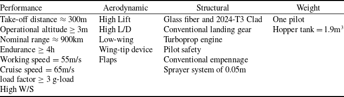
The agricultural aircraft (AG-Nel 25) was developed through the application of low-order models for aerodynamics, weight and balance, propulsion and performance, providing a means for capturing most of the effects that are relevant to the mission profile of an agricultural aircraft. Based on traditional aircraft design methods, such as the ones described in [Reference Raymer29–Reference Nicolai31], the project started by specifying the mission requirements, which are summarised in Table 2. During the preliminary sizing, emphasis was given on the wing design and pilot ergonomics towards reducing the risks associated with this aircraft modality, due to the low altitude it involves, subjecting the pilot to flying within the limits of the operating aircraft envelope [Reference Ravelli, Zerbato, Oliveira and Corrêa32]. Thus, the main characteristics of the AG-Nel 25 aircraft include a rectangular wing with a
 ${7^ \circ }$
dihedral angle that aids on wingover manoeuvers, and a cockpit that provides adequate visibility to avoid potential unforeseen shocks and obstacles. After defining the main concept, a parametric multi-winglet design procedure was implemented in order to enhance aircraft performance and manoeuverability in low-speed flights [Reference Céron-Muñoz, Cosin, Coimbra, Correa and Catalano26]. The last AG-Nel 25 version included an adaptive multi-winglet device (
 ${45^ \circ }{,15^ \circ }$
, and
 $ - {15^ \circ }$
cant angles of each winglet), whose final configuration was selected after CFD simulations. This configuration provided a considerable increase in lift-to-drag (L/D) ratio, suggesting a reduction in fuel burn. The multi-winglet device reduced the wingtip vortex intensity, thus benefiting spray dispersal patterns. It should be noted that the first version of the aircraft may also be adapted into fire-fighting or armed versions, whose requirements differs from the ones presented in this paper. For more details of the aircraft concept developed through the low-order models, see Bravo-Mosquera et al. [Reference Bravo-Mosquera, Cerón-Muñoz, Daz-Vázquez and Catalano27].
Although the overall configuration was defined during the conceptual design phase, several modifications in the geometry continue to be evaluated. Figure 4 shows an external 3D CAD view of AG-Nel 25 and basic geometric characteristics, from the last stages of the conceptual design phase. The considerable potential of WLE for controlling the flow on wings is an interesting opportunity for reevaluations of the AG-Nel 25 performance because low Reynolds numbers are operated on winglets, and the control of flow separation can improve both aerodynamic performance and efficiency. For an aircraft that performs this kind of missions, maximising the flight time and range is of major importance. Therefore, a comparison between the performances of the multi-winglet device and the WLE winglet was conducted on the basis of the AG-Nel 25 mission.
AG-Nel 25 aircraft (multi-winglet and WLE winglet versions evidenced, dimensions in metres).

4.0 Aerodynamic analyses
4.1 Experimental setup
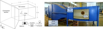
The models shown in Fig. 3 were manufactured in Polylactic Acid (PLA) by a 3D printer to perform a complete aerodynamic analysis of the proposed winglets. The experimental tests were conducted in a blower-type wind tunnel (closed wall test section of
 $1{\rm{m}}\; \times \;0.8{\rm{m}}\; \times \;2.15{\rm{m}}$
) of the Department of Aeronautical Engineering, São Carlos School of Engineering University of São Paulo. The 25.5kW engine power of the wind-tunnel provides a maximum air speed of 25m/s with an approximately 0.15% turbulence intensity. The models were attached to the wind-tunnel wall via a round aluminum sting in a horizontal and inverted position. This ensured that the models are close to the tunnel’s center section, where the smoothest flow is expected. Figure 5 shows the position of the model inside of the wind tunnel: schematic view with instrumentation setup (left), and actual facility (right).
Schematic of blower-type wind-tunnel at São Carlos Engineering School, University of São Paulo, dimensions in metres.

Atmospheric conditions were measured with a weather station, namely: 92.3kPa static pressure,
 ${23^ \circ }$
C static temperature, and 1.08kg/m
 $^3$
density, and the air speed was measured with a pitot-tube and a micro manometer (
 $ \pm $
0.1Pa uncertainty). The aerodynamic forces were measured with a TE- 81 aerodynamic balance (
 $ \pm $
0.02N uncertainty), which can assess lift and drag. It was set to take 7,000 samples at 700 samples per second frequency, resulting in a time-averaged values of those coefficients. Similar measurements were already performed using the current experimental setup [Reference Bravo-Mosquera, Vaca-Rios, Diaz-Molina, Amaya-Ospina and Cerón-Muñoz33, Reference Garcia-Ribeiro, Bravo-Mosquera, Ayala-Zuluaga, Martinez-Castañeda, Valbuena-Aguilera, Cerón-Muñoz and Vaca-Rios34]. Measurements were performed at
 $2.09 \times {10^5}$
Reynolds number (based on a 0.15m baseline aerofoil chord and 22m/s freestream velocity) and the
 $\alpha $
range was set from
 $ - {2^ \circ }$
to
 ${20^ \circ }$
. Due to the model scale and the low Reynolds number of the test, trip strips of 0.3mm in height were placed approximately
 $5\% $
of chord far from the wing leading edge to hasten the flow transition from laminar to turbulent. The height and position of the trip were selected to provide the lowest possible drag and maximum lift, whereas a linear relationship between
 ${C_L}$
and
 $\alpha $
in the prestall regime is maintained, as recommended in Ref. barlow1999low. It was challenging to select a standardised trip position over the
 ${W_{A08L24}}$
winglet due to the variable chord length along its span. However, it was determined that tripping the winglet in this area has negligible effects on maximum
 ${C_L}$
, since the tubercles already generate the contra-rotating vortex. Since the model is mounted on a turntable flush with the tunnel wall, the forces on the turntable are included in the recorded data by the load-cells. The absolute value of the drag was then calculated by subtracting the drag of the turntable from the one with the model attached. In contrast, the effect of the turntable on lift is negligible. The wing model and turntable constituted approximately 1.25% and 2% of the cross-sectional area of the test section, respectively, and therefore blockage effects were expected to be minor [Reference Barlow, Rae and Pope35]. Furthermore, the wing chord is small relative to the width of the test section. Therefore, the lift interference effects were also considered to be small. Consequently, no blocking corrections were applied thereafter.
These experiments were repeated multiple times after several installations. A polynomial curve-fit is applied to data taken during a given run. The standard deviation of all the polynomial curve-fits was analytically computed. Repeatability is quoted as the 95% confidence interval, being
 $\Delta {C_L} = 0.0028$
and
 $\Delta {C_D} = 0.0035$
. Lastly, flow visualisation tests were conducted over the upper surface of
 ${W_{Baseline}}$
and
 ${W_{A08L24}}$
winglets. The oil-flow visualisation technique was used, in which the wing surfaces were covered with a fine pigment of vegetable oil mixture. This enabled the visualisation of flow separation, reattachment, recirculation zones and vortex trace.
4.2 Numerical simulations
CFD simulations were used to validate the wind tunnel data, where the unknown Reynolds stress tensor was solved by turbulence modeling. The
 $\kappa - \omega $
SST (Shear Stress Transport) model was selected due to its capability of predicting turbulence effects in higher-order terms [Reference Steed36] and for presenting accurate results in similar conditions as herein studied [Reference Chen, Qiao and Wei18, Reference Shi, Atlar, Norman, Aktas and Turkmen37]. The RANS equations were discretised by the finite volume method in incompressible steady-state condition, according to the numerical methodology implemented in ANSYS Fluent [Reference Matsson38]. Since the purpose of this study is to assess the WLE potential to increase the aerodynamic performance of winglets at low
 $\alpha $
, no additional resources were invested on achieving accurate aerodynamic predictions at high
 $\alpha $
, as also has been performed by [Reference Chen, Qiao and Wei18, Reference Shi, Atlar, Norman, Aktas and Turkmen37, Reference Cai, Zuo, Liu and Wu39].
Both atmospheric and flow conditions of the experimental setup were adjusted to the computational environment. The boundary domain was designed as a virtual box of same dimensions of the wind tunnel test section, thus ensuring the models were located at the same distance from the inlet and outlet. Uniform velocity was set at the inlet (0.064 Mach number) with 0.1% freestream turbulence, as in the actual wind tunnel. The standard atmosphere pressure condition was employed at the outlet, whereas a symmetry condition was applied in the longitudinal plane. The boundaries at the bottom, lateral and top sides of the computational domain were set up as ideal walls where free slip condition was imposed. This means that there is no gradient in the wall-normal direction of the wall-parallel component. In contrast, a no-slip wall condition was set up for the wing surface. Transition is not modeled, and the flow is assumed to be fully turbulent. This is meaningful, as the wind-tunnel flow quality is unlikely to promote extensive laminar flow. The convergence control was set towards reaching 600 iterations, with a maximum residual target of
 $1 \times {10^{ - 5}}$
.
The surfaces were discretised with predominantly unstructured 3D cells of a size that varied depending on the individual body geometry. The final meshes were derived by several grid independence studies from an initial mesh to a final one, named here as Mesh 1, Mesh 2 and Mesh 3, respectively, which are progressively refined. Figure 6 displays the obtained values of lift and drag coefficients for each mesh, which were run under wind tunnel experimental conditions for
 $\alpha = $
0
 $^ \circ $
, 4
 $^ \circ $
, 8
 $^ \circ $
, and 10
 $^ \circ $
. For a quantitative comparison, Table 3 shows the grid study statistics for
 $\alpha { = 0^ \circ }$
. Between Mesh 1 and Mesh 2, the lift and drag coefficients change by 10.5% and 9.03%, respectively, while between Mesh 2 and Mesh 3, the variation of both coefficients is minimum. For this reason, Mesh 2 is the best option as it allows obtaining accurate results with lower computational costs.
Mesh independence study of
 ${W_{A08L24}}$
winglet.

Design requirements of the AG-Nel 25 aircraft (Adapted from Bravo-Mosquera et al. Reference Bravo-Mosquera, Cerón-Muñoz, Daz-Vázquez and Catalano27.).

Grid refinement study at
 $\alpha = 0^ \circ $
for
 ${W_{A08L24}}$
winglet

Unstructured tetrahedral elements were used to generate the mesh, where smooth refinements were applied to the wing, winglet and wake regions. The mesh is refined towards the wall surfaces up to a non-dimensional wall distance of
 ${y^ + } \approx 1$
. Once obtained the height of the first layer, the geometric growth rate of the inflation layers had to be modified in order to increase or decrease the number of layers inside each inflation zone. An inflation with 20 layers with a growth rate of 1.2 was enough to cover the boundary layer thickness. The mesh quality was monitored to provide precise outcomes, where the maximum obtained skewness was
 $0.95$
with
 $0.22$
average and
 $0.12$
standard deviation. Figure 7 shows the final mesh over the WLE winglet, including details of the near wall layers.
Mesh global view of
 ${W_{A08L24}}$
winglet.

The second phase of this study focused on a comparison between the current multi-winglet device of AG-Nel 25 against the WLE winglet installed on the aircraft. The primary objective was to provide more accurate information about the flow field around the entire configuration. Therefore, a wide computational domain was designed for this case, avoiding the influence of the wall boundaries on the flow. The Reynolds number was calculated to be approximately
 $7 \times {10^6}$
, based on the full-scale mean aerodynamic chord and working aircraft speed. Note the Reynolds numbers in the wind tunnel and in flight differ significantly and might impact the behaviour of the WLE. However, appropriate boundary layer trips on all surfaces ensured turbulent flow for wind tunnel cases, whereas a fully turbulent flow was assumed for the full-scale simulations. Thus, the results can be scaled to full-size aircraft Reynolds numbers. All boundary conditions and physical modelling adopted here are the same reported by Bravo-Mosquera et al. [Reference Bravo-Mosquera, Cerón-Muñoz, Daz-Vázquez and Catalano27]. This decision was made by considering the capability of the methodology to capture the turbulence effects with greater clarity.
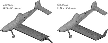
An unstructured mesh around the entire aircraft geometry was generated (Fig. 8); it consisted of approximately
 $11.78 \times {10^6}$
elements for the multi-winglet concept, and
 $11.51 \times {10^6}$
elements for the WLE winglet concept. The flow field was examined by employing RANS simulations coupled with the SST turbulence model. The turbulence model was validated multiple times and has proven reliable in recent studies involving full-configuration aerodynamics [Reference Bravo-Mosquera, Abdalla, Cerón-Muñoz and Catalano40, Reference Eguea, Bravo-Mosquera and Catalano41]. Such flows are largely affected by unsteadiness and separation effects, which are challenging to capture with simulations. However, adequate predictions were achieved at the moderate flight conditions. Results from this aerodynamic analysis were used in the reevaluation of the performance characteristics of AG-Nel 25, bearing in mind the application stage of its mission profile, i.e. the range of
 $\alpha $
at which the L/D ratio is maximum.
AG-Nel 25 surface mesh.

5.0 Results and discussion
5.1 Aerodynamics
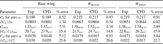
In this section, the CFD and experimental results for the winglet configurations are analysed and compared. The base wing configuration (i.e. without wingtip device) was also included to improve the generality of the ranking. The studied variables were: lift coefficient, aerodynamic efficiency, drag polar, and induced drag, which served to interpret the potential benefits of the application of WLE to enhance winglet aerodynamic performance. The goal of this investigation is to determine whether it is possible to design a WLE winglet by first identifying critical issues in an experimental and numerical application. Table 3 shows a summary of the results from the experimental-numerical comparison, and Figs 9 and 10 display the complete aerodynamic comparison for several angles of attack.
Numerical and experimental comparison of lift coefficient.

Numerical and experimental comparison of drag coefficient.

According to the results of Fig. 9a, the lift curves show great agreement between numerical and experimental results, especially for low to moderate
 $\alpha $
. From
 $\alpha = $
 $ - {2^ \circ }$
to
 ${10^ \circ }$
, the curves display a linear behaviour with a similar slope with an accuracy of less than 1% error. Therefore, CFD simulations show high precision in the pre-stall region by matching experimental data. As the configurations approach the stall condition, CFD simulations predict a smoother flow detachment than measured in the experiment, resulting in higher lift coefficients for the same
 $\alpha $
. An accurate prediction requires transient simulations, which needs more computational effort, and is beyond the scope of this paper. By comparing the configurations, the
 ${W_{Baseline}}$
winglet has provided a slightly higher stall angle than the base wing due to its ability to delay flow separation emanating from the tip. This is followed by the
 ${W_{A08L24}}$
winglet, which provides the highest
 ${C_L}$
and stall angle (see Table 3). This phenomenon resembles the typical findings from previous investigations on the leading-edge protuberance [Reference Weber, Howle, Murray and Miklosovic10, Reference Wei, Lian and Zhong23, Reference Papadopoulos, Katsiadramis and Yakinthos25, Reference Florez, Bravo-Mosquera, Garcia Ribeiro and Cerón-Munoz42]. It indicates that the stall characteristics are much more gradual with wavy aerofoils than with smooth aerofoils, and the amount of lift generated in the poststall regime is also greater.
Figure 9b shows the aerodynamic efficiency curves versus lift coefficient. This plot clearly shows the aerodynamic advantages that the winglet configurations bring in terms of flight range and efficiency. A good agreement between CFD simulations and experiment data for low
 $\alpha $
is visible. However, as
 $\alpha $
increases, some weaknesses in the drag prediction leads to considerable errors (around 15% for maximum
 ${C_L}/{C_D}$
). Despite such difference, all three configurations deliver their best performance at
 $\alpha { = 4^ \circ }$
and the trend is maintained between the methods, although their relative magnitude of
 ${C_L}/{C_D}$
differs (see Table 3). For the lift coefficient that maximise the aerodynamic performance, the
 ${W_{A08L24}}$
winglet is
 $8.4\% $
and
 $4.9\% $
more efficient than the base wing and
 ${W_{Baseline}}$
winglet, respectively. These variations were to be expected because the
 ${W_{A08L24}}$
winglet produced a higher lift and lower drag compared to the other configurations for most of the angle-of-attack range considered.
Figure 10a depicts the drag polar results. Although the CFD curves showed lower drag coefficient values, both numerical and experimental results were fairly adequate, specially for lower angles of attack. However, at higher angles of attack, a considerable dispersion was observed in both lift and drag predictions due to the higher level of complexity in the flow pattern arising from the nearby stall region, which is more difficult to be numerically simulated. Despite such results, for a given magnitude of
 ${C_D}$
, the
 ${W_{A08L24}}$
winglet shows an increased
 ${C_L}$
magnitude when compared to the other configurations evaluated. The effect of flow control is also noticeable on the drag polar. For example, the aerodynamic coefficients of the
 ${W_{A08L24}}$
winglet exhibit a relatively mild transition around the stall region, implying an attenuated stall compared with the
 ${W_{Baseline}}$
winglet. In contrast, for the base wing, the drag continues to increase whereas lift reduces beyond the stall limit. In this case, the maximum lift coefficient is significantly lower as compared to the configurations with winglets. This observation points towards the fact that the maximum lift requirement of an agricultural aircraft can be achieved at a much lower angle-of-attack upon designing the wing with proper wingtip device.
Finally, Fig. 10b depicts the variation of drag coefficient with the square of lift coefficient at several angles of attack. The total drag (
 ${C_D}$
) is the sum of the zero-lift drag (
 ${C_{D0}}$
), which is related to the geometry complexity, and induced drag (
 ${C_{Di}}$
), which is related to the three dimensional effects of the wing (see Equation (1), where k is the induced drag constant). In this context, the wavy aerofoil effect on each drag component is assessed in Fig. 10b. The CFD simulations underpredict these variables compared to experimental data, within 20% relative error (see Table 3). Reasons could be uncertainty in the wind tunnel tests and/or the relative numerical error of RANS prediction; although the trend in both methodologies is maintained. It can be seen how the
 ${C_{D0}}$
tends to be higher with the presence of the winglets, resulted from the added wetted area, in comparison with the wing without winglet. However, the induced drag slope (
 $\partial {C_D}/\partial C_L^2$
) in the linear region is reduced by the winglets. This indicates that even if the zero-lift drag has increased, the contribution of the induced drag to the total drag is decreasing as the angle-of-attack increases. Note that the
 ${W_{A08L24}}$
winglet reduced the induced drag slope when compared to the
 ${W_{Baseline}}$
winglet. This reduction can be a consequence of the WLE fence effect, which counteracts the cross-flow towards the winglet tip, thus reducing the intensity of its vortex.
 \begin{equation}{C_D} = {C_{D0}} + k \cdot C_L^2.\end{equation}
5.2 Visualisation results
Flow visualisation tests were conducted for
 ${W_{Baseline}}$
winglet and
 ${W_{A08L24}}$
winglet at
 $\alpha { = 4^ \circ }$
(see Fig. 11). For the
 ${W_{Baseline}}$
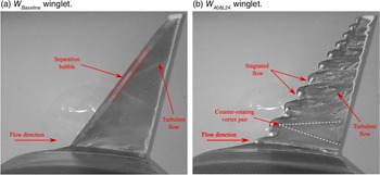
winglet (Fig. 11a), the flow separates and reattaches on the suction surface, creating a separation bubble that is stretched in the spanwise direction. In contrast, it can be observed the presence of oil-flow stagnated on the WLE valleys of the
 ${W_{A08L24}}$
winglet (Fig. 11b). In this case, the trace of the flow behind the WLE seems to indicate the presence of counter-rotating vortices, which are uneven and slightly displaced towards the winglet tip. This result is explained by the sweep angle of the winglet, which is consistent with calculations undertaken in Refs [Reference de Paula, Rios Cruz, Ferreira, Kleine and da Silva22, Reference Wei, Lian and Zhong23]. Furthermore, no clear trace of separation is observed close to the leading edge, thus evidencing that the counter-rotating vortices effectively delayed the flow separation behind the valleys. This barely influenced the wing total lift, as shown in Fig. 9a, but evidences the WLE fence effect that reduces the cross-flow towards the winglet tip and wing induced drag.
Oil-flow visualisation in wind-tunnel experiments at
 ${4^ \circ }$
.

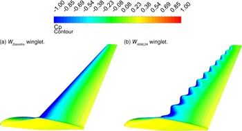
Figure 12 displays the pressure contours obtained by the numerical analysis. The fact that the pressure distributions are similar demonstrates that the CFD methodology is capable of evaluating the geometrical properties of aerodynamic configurations, producing suitable pressure results within a specific range of the accuracy criterion. In this context, pressure over the
 ${W_{A08L24}}$
winglet corresponds to its leading edge format, i.e. low pressure cells appear at its valleys and decrease in size as the WLE does towards the winglet tip, which is consistent with the experimental visualisation tests. Such reduced pressure indicates faster flow velocity and increased lift at low-to-moderate angles of attack.
Pressure coefficient contours in CFD simulations at
 ${4^ \circ }$
.

The change in the pressure distribution of the base wing compared to the winglet configurations is shown below. Figure 13 shows the pressure coefficient (
 ${C_p}$
) values obtained from the numerical simulations at some wingspan locations, where
 ${C_p}$
is computed as follows,
 \begin{equation}{C_p} = \frac{{p - {p_\infty }}}{{{q_\infty }}},\end{equation}
Pressure coefficient on the wing surface at
 ${4^ \circ }$
.

where p is the pressure at the point in which the pressure coefficient is being evaluated,
 ${p_\infty }$
is the pressure in the freestream, and
 ${q_\infty }$
is the dynamic pressure of the freestream. There is almost no change in the pressure distribution between the
 ${W_{Baseline}}$
winglet and
 ${W_{A08L24}}$
winglet, so the static pressure distributed along the wingspan remains unchanged with the addition of the leading edge protuberances on the winglet. This means that the improvements observed in Section 5.1 are solely due to effects of the leading edge protuberances on the winglet, and consequently on tip vortices. In contrast, the effect of the winglets over the
 ${C_p}$
of the base wing is clearly evidenced, in which the area enclosed by the static pressure distribution curves becomes larger, i.e. the lift generated by the winglet configurations is greater than that of the base wing. This effect is more apparent towards the wingtip, as a result, the outer portion of the wing carries a higher load than it does without the winglet.
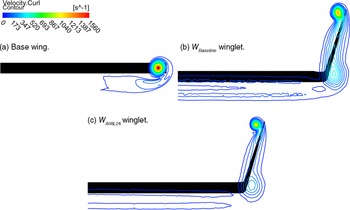
Figure 14 shows the flow patterns obtained via numerical simulations at
 ${4^ \circ }$
. Vorticity contours downstream the wing at a plane located at
 $x/c$
= 1.6, where c is the chord length and x is the free-stream velocity axis, are used for visualisations of the flow around the configurations. The Fig. 14a shows the main vortex of the base wing, which is expected to increase in strength and magnitude as it spreads in the wake. In contrast, the
 ${W_{A08L24}}$
winglet reduces the magnitude and intensity of the wingtip vortex (Fig. 14c) when compared to the other configurations (Figs. 14a and 14b). This is possibly because the
 ${W_{A08L24}}$
winglet inhibits spanwise flow where accelerated flow in valleys regions maintains attachment, which limits the drag penalty from the wingtip vortex core. Therefore, both the spanwise flow limitation and accelerated flow through valleys regions provide a considerable reduction in the induced drag compared to the base wing and the
 ${W_{Baseline}}$
winglet.
Experimental and CFD results comparison

Flow patterns of vorticity around the configurations obtained via numerical simulations at
 ${4^ \circ }$
.

5.3 Application on the AG-Nel 25 aircraft
The results of the flow modeling around the agricultural aircraft are presented in this section. Endurance and range capabilities of AG-Nel 25 were reevaluated with the use of the WLE winglet. The approximate solutions for endurance (Equation (3)) and range (Equation (4)) for propeller-driven aircraft are given by:
 \begin{equation}{E_i} = \frac{{{\eta _p}}}{{{c_t}}}\;\sqrt {2\rho S} \;\frac{{C_L^{3/2}}}{{{C_D}}}\;\left( {\frac{1}{{\sqrt {{W_i}} }} - \frac{1}{{\sqrt {{W_{i - 1}}} }}} \right)\end{equation}
 \begin{equation}{R_i} = \frac{{{\eta _p}}}{{{c_t}}}\;\frac{{{C_L}}}{{{C_D}}}\;Ln\left( {\frac{{{W_{i - 1}}}}{{{W_i}}}} \right)\end{equation}
where
 ${\eta _p}$
is the propeller efficiency,
 ${c_t}$
is the thrust specific fuel consumption,
 $\rho $
is the air density, S is the wing surface and
 ${W_i}$
is the weight of the aircraft at the end of mission segment i. Since each segment is associated with a weight fraction, values for take-off and climb phases were obtained from historical data [Reference Raymer29]. Specific fuel consumption and propeller efficiency were calculated using the propeller and engine manufacturer charts, and both altitude and angle-of-attack are considered constants. Table 5 shows the results of the aircraft simulations at a freestream velocity of 60
 ${\rm{m}}/s$
and an angle-of-attack of 4
 $^ \circ $
that simulates the working condition of the agricultural aircraft. It can be seen that the WLE winglet offered a considerable reduction in drag and an increase in lift than the multi-winglet device. These results are due to a number of reasons, including a reduction in wetted area and an increase in the effective aspect ratio, resulting in maximum efficiency at a higher lift coefficient. Consequently, the calculations show that the WLE winglet improved operating time and range by 4.1% and 3.4%, respectively, in comparison with the multi-winglet device. On the other hand, one of the major benefits of wingtip devices is that they provide a performance increase while only fractionally increasing the root bending moment on the spar. This is a useful parameter to verify the influence of wingtip devices on structural loading. The comparison of the root bending moment coefficient
 $({C_{Mr}})$
between the configurations shows that multi-winglets do not increase substantially the bending moment at the wing root. These results highlight the possible advantages that a WLE winglet may have over other geometries previously selected for aerodynamic efficiency enhancement.
Comparison between the multi-winglet and WLE winglet installed on the AG-Nel 25 aircraft at
 $\alpha = 4^ \circ $

Q-criterion on the AG-Nel 25 aircraft at
 $\alpha { = 4^ \circ }$
.
 $Q = 4 \times {10^{ - 5}}\;{s^{ - 2}}$
.

Figure 15 illustrates the iso-surfaces of the Q-criterion (
 $4 \times {10^{ - 5}}\;{s^{ - 2}}$
) on the aircraft including close-up views of the wingtip upper surfaces at
 $\alpha { = 4^ \circ }$
, which is the angle of maximum aerodynamic efficiency. Note the main wing vortex of the multi-winglet device (Fig. 15a) is larger than that of the WLE winglet (Fig. 15c), suggesting the vortices produced by the WLE winglet dissipate much faster at the wake extension, which can be useful for an agricultural aircraft to reduce spray dispersal on crops. However, this last topic requires further investigations, which were not performed here. Likewise, the flow eddies are highly disordered on the multi-winglet devices, where the vortex core velocity contour tends to zero near the trailing edges of each tip sails (Fig. 15b). This can be one of the factors contributing to the increased overall friction drag of this configuration. In contrast, the flow control provided by the WLE winglet improved the flow attachment by generating longitudinal vortices, where the flow remains attached near the trailing edge of the wingtip (Fig. 15d), resulting in a higher aerodynamic efficiency.
6.0 Conclusions
This study assessed the performance effects of winglets with wavy leading edge on a rectangular wing and then on an agricultural aircraft. Wind tunnel tests and numerical simulations showed clear differences in aerodynamic performance between the evaluated configurations. The WLE winglet performed better than the baseline winglet, reducing the induced drag coefficient and demonstrating a clear benefit for a wide range of angles of attack.
The evidence provided by the force measurements and flow visualisation demonstrated that the tubercles of the WLE winglet delay the flow separation. They reduced cross-flow towards the winglet tip, which decreased vortex circulation resulting in a higher aerodynamic efficiency. Furthermore, the WLE winglet demonstrated relatively mild transition around the stall region, implying an attenuated stall compared with the baseline winglet, which can also benefit the structural stability of the wing.
These results were used to compare the performance of the WLE winglet and a multi-winglet device on the aerodynamic performance of an agricultural aircraft. Numerical simulations showed that the WLE winglet optimised the aircraft L/D ratio, which suggests an increase in its operational time along the mission profile. It should be noted that implementing this kind of technology requires development and certification work, as well as a financial investment. The expenses and economic benefits of this new winglet must be addressed in a future research. Moreover, one must have in mind that the aerodynamic performance may differ for another aircraft configuration and operational conditions such as the Re number and the angle-of-attack.
In sum, this paper is a first-step approach to assess the use of WLE on winglets. It was proved that WLE can potentially enhance the aerodynamic performance of winglets on rectangular wings. To achieve a deeper understanding of the effects of winglets with WLE, future studies will comprehend CFD simulations in unsteady regime and the use of more computationally expensive turbulence approaches, such as the Improved Delayed Detached Eddy Simulation or the Large Eddy Simulation. The effects of varying the WLE alignment, configuration (i.e.
 $A/\lambda $
ratio), and size on the winglet performance will also be assessed in more detail so that an optimum WLE design on winglets is achieved.
Acknowledgments
The authors acknowledge the financial support of CNPq (Conselho Nacional de Desenvolvimento Científico e Tecnológico) – Grants 141950/2017-0 and 131689/2018-5, and Professor Dr. Fernando M. Catalano for providing the facilities of the Experimental Aerodynamics Laboratory (LAE-1).
Declaration of competing interest
The authors declare they have no competing financial interests or personal relationships that might influence the work reported in this paper.