1. Introduction
Ion-acoustic waves (IAWs) are modes of ion oscillations often observed in plasmas. These are low-frequency longitudinal oscillations, which take place with the electrons in the background. These background electrons provide the restoring force essential for the ion oscillations (Hosseini Jenab, Kourakis & Abbasi Reference Hosseini Jenab, Kourakis and Abbasi2011). The first theoretical prediction of IAWs was reported by Tonks and Langmuir in 1929 (Tonks & Langmuir Reference Tonks and Langmuir1929). Such waves were experimentally observed by Revans in 1933 (Revans Reference Revans1933) for the first time in a gas discharge tube. The study of IAWs is a very classical area of research in plasma physics, which includes both the linear and nonlinear modes of waves (Mahmood, Mushtaq & Saleem Reference Mahmood, Mushtaq and Saleem2003). Thomson in 1933 derived the equation of IAWs using the fluid theory (Thomson & Thomson Reference Thomson and Thomson1933). Damping of the IAWs is one of its intrinsic properties, classified in two categories viz. Landau damping and collisional damping. Out of these, the Landau damping of the IAWs occurs when the electron temperature ($T_e$ ) is approximately equal to the ion temperature ($T_i$
 ). The damping and propagation of the IAWs can easily be studied, if the wave in the plasma is excited using an external source. Wong, Motley & D'Angelo (Reference Wong, Motley and D'Angelo1964) excited IAWs with the help of a negatively biased grid and consequently studied Landau damping of the waves.
The presence of negative ions in a plasma can have a significant effect on the properties of IAWs. It was observed that when the fraction of negative ions is large, the IAWs split up into two modes, out of which, the faster one undergoes weak Landau damping (D'Angelo & Merlino Reference D'Angelo and Merlino1996). Not only this, the pulse velocity of the wave is identical to its phase velocity (Alexeff & Jones Reference Alexeff and Jones1965). In addition to this, there are instances when two groups of electrons are present in the system, namely the hot and cold. The IAWs are highly responsive to such situations (Sharma et al. Reference Sharma, Adhikari, Moulick, Kausik and Saikia2020). The IAWs are also studied in a plasma containing two-temperature electrons. In a two-electron temperature plasma, the electron group with lower energy has the dominant effect on the propagation of IAWs (Jones et al. Reference Jones, Lee, Gleman and Doucet1975).
In the presence of dust particles, the IAWs get modified as dust ion acoustic waves (DIAWs). The DIAWs propagate in the range of frequencies $kv_{{\rm th},i} \ll \omega \ll kv_{{\rm th},e}$ , where $\omega$
 , $k$
 , $v_{{\rm th},i}$
 and $v_{{\rm th},e}$
 are the angular wave frequency, wavenumber, ion thermal velocity and electron thermal velocity, respectively. It has been found that DIAWs travel with higher phase velocity than the usual IAWs (Merlino et al. Reference Merlino, Barkan, Thompson and D'Angelo1997). Barkan, D'Angelo & Merlino (Reference Barkan, D'Angelo and Merlino1996) studied DIAWs in a Q-machine, in which it was observed that in the presence of dust grains, the phase velocity of IAWs increases, causing a decrease in the Landau damping. The dispersion relation and rate of Landau damping of DIAWs were derived by a kinetic approach (Hadi & Qamar Reference Hadi and Qamar2019). Nakamura, Bailung & Shukla (Reference Nakamura, Bailung and Shukla1999) studied linear and nonlinear DIAWs in a homogeneous unmagnetized dusty plasma. The results of the study are significant in the sense that for the linear regime of the wave, the phase velocity and damping increase with the increase in dust density.
Despite a significant number of studies, it is observed that the study of the properties of the IAWs in presence of an external magnetic field is an unexplored area of research. This motivates us to perform this specific study of IAWs in the presence of an external magnetic field. The IAWs are widely used as a diagnostic tool to determine the electron temperature and ion mass of plasma. In addition, they are used to estimate the relative ion concentrations in a two positive ion species plasma, as well as the relative concentration of the negative ions (Hershkowitz & Kim Reference Hershkowitz and Kim2008; Saikia et al. Reference Saikia, Saikia, Goswami and Phukan2014; Kakati et al. Reference Kakati, Kausik, Bandyopadhyay, Saikia and Kaw2017). Negative ions are the prime participants for the neutral beam injection in an ITER tokamak. The production of negative ions in plasma involves two methods, volume and surface production. The surface production has better efficiency over the volume process (Kakati et al. Reference Kakati, Kausik, Bandyopadhyay, Saikia and Kaw2017). It has been established that the density of negative ions increases in the presence of an external magnetic field (Santoso et al. Reference Santoso, Manoharan, O'Byrne and Corr2015). In a low-pressure plasma, a novel surface-assisted volume negative hydrogen ion source has been developed by using caesium (Cs) coated tungsten (W) dust (Kakati et al. Reference Kakati, Kausik, Bandyopadhyay, Saikia and Kaw2017). The presence of an external magnetic field in these studies may lead to an efficient negative ion source by enhancing the density of the negative ions. As the present study deals with the propagation of IAWs in an external magnetic field, the findings of the study may be helpful to estimate the density of the above-mentioned negative hydrogen source where the presence of magnetic field is essential. This can be a future prospect of the present study.
In this article, we intend to understand the effect of an external magnetic field on the propagation and damping of the linear IAWs. Moreover, the propagation of IAWs depends on the temperature of the electrons in the plasma. It is a well-known fact that in a plasma with two distinct groups of electrons, the colder electrons have a dominant effect on the IAWs. The effect is prominent even if the plasma contains only $10\,\%$ cold electrons. The optical techniques often fail to detect the presence of such cold electrons in the plasma. For those plasmas containing hot electrons as the dominant group, the IAWs acts as a suitable diagnostic tool to determine the presence of cold electrons (Jones et al. Reference Jones, Lee, Gleman and Doucet1975). Moreover, dust charging study in a two-electron temperature plasma has revealed secondary electron emissions (SEE) from tungsten dust grains (Paul et al. Reference Paul, Sharma, Deka, Adhikari, Moulick, Kausik and Saikia2022). The study shows that the SEE from the dust grains results in an increase in the density of cold electrons, which is expected to have a significant effect on the propagation of IAWs. The present study aims to investigate the role of the two-electron groups on the characteristics of IAWs in the presence of dust and an external magnetic field.
The paper has been organized as follows. In § 2, the production mechanism of the plasma, IAWs excitation and detection have been described. Analysis of the results observed in the experiment is presented and discussed in § 3. The conclusions of the study are drawn in § 4.
2. Experimental set-up
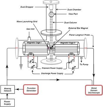
The experimental study of IAWs has been carried out in a cylindrical stainless steel chamber consisting of horizontal and vertical chambers. The experimental chamber looks like an inverted $T$ , as shown in figure 1. The plasma is produced in the horizontal chamber, having a length of 100 cm and a diameter of 30 cm. On the other hand, the vertical chamber is used as the dust dropping unit with a height of 72 cm and a diameter of 15 cm. The chamber is evacuated to a base pressure of $1.5\times 10^{-5}$
 mbar using a diffusion pump backed by a rotary pump. The working pressure of the hydrogen gas is maintained at $1.7\times 10^{-4}$
 mbar. A hot cathode filament discharge method has been used to produce the plasma. The primary electrons emitted by the filaments are accelerated by a biasing voltage in the range of 80–90 V, which participate in the ionization of the gas and produce secondary electrons. These secondary electrons are accelerated by the biasing voltage and produce further ionization. Thus, a sustainable discharge condition is achieved. Plasma with two distinct groups of electrons having different temperatures is achieved by inserting two magnetic cages of different surface field strengths (magnetic cage I, 1.2 kG made of strontium ferrite; magnetic cage II, 3.5 kG made of a samarium cobalt) inside the chamber, as depicted in figure 2. Different discharge currents are maintained in the two cages by suitably controlling the filament currents. The discharge current in cage I is fixed at $0.5$
 A, whereas in cage II it was varied from 1–3 A at a step of $0.5$
 A. Thus, two different plasmas are produced in the individual cages. The plasmas so produced diffuse at the junction of the two cages, and consequently the plasma at the junction consists of two-electron groups with different temperatures (Sharma et al. Reference Sharma, Deka, Paul, Adhikari, Moulick, Kausik and Saikia2022). The semilogarithmic plot of I–V having two distinct slopes, as displayed in figure 3, confirms the presence of two different electron species with distinguishable temperatures.
Schematic diagram of the experimental set-up.

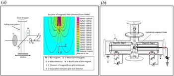
(a) Relative positions of grid, detector, magnet and dust column along with the magnetic field strength and field lines of the bar magnet. FEMM, Finite element method magnetics. (b) Schematic of experimental set-up used for characterization of plasma using cylindrical Langmuir probe.

Langmuir probe I–V characteristics in semilogarithmic scale depicting the presence of two-electron temperatures.

The upper and lower slopes give the electron temperatures of cold ($T_{\rm ec}$ ) and hot ($T_{\rm eh}$
 ) components, respectively (Pustylnik, Ohno & Takamura Reference Pustylnik, Ohno and Takamura2006; Pilling & Carnegie Reference Pilling and Carnegie2007).
The effective electron temperature of the plasma is given by (Jones et al. Reference Jones, Lee, Gleman and Doucet1975)

where, $n_e$ , $n_{\rm ec}$
 and $n_{\rm eh}$
 are the total plasma density, density of cold and hot components of the electrons, respectively.
The phase velocity of the IAWs in a two-electron temperature plasma (Jones et al. Reference Jones, Lee, Gleman and Doucet1975) takes the form

where, $\omega$ , $k$
 , $k_B$
 , $T_{\rm eff}$
 and $m_i$
 are angular frequency, wavenumber, Boltzmann constant, effective electron temperature and mass of the ion, respectively.
In this experiment, the IAWs have been excited by inserting a mesh grid into the plasma column (Wong et al. Reference Wong, Motley and D'Angelo1964; Barkan et al. Reference Barkan, D'Angelo and Merlino1996), which is made of stainless steel, having a diameter of $5$ cm with transparency of $\approx 75\,\%$
 . For appreciable density modulation, the inner-wire spacing of the grid should be comparable to the Debye length and ion gyroradius (Barkan et al. Reference Barkan, D'Angelo and Merlino1996; Shukla & Mamun Reference Shukla and Mamun2001). In the present context, the Debye length and ion gyroradius are $\approx 0.1$
 mm and $0.115$
 mm, respectively. Therefore, the inner-wire spacing of the grid is $\approx 0.5$
 mm, and its surface is perpendicular to the axis of the plasma column. For launching the IAWs, a transistor-based biasing circuit was designed and fabricated, and a sinusoidal voltage, having a frequency in the range of 80–120 kHz with peak-to-peak voltage 4–5 V applied to it. The applied signal creates a density perturbation, and consequently, it propagates through the plasma as IAWs. A planar Langmuir probe (floating) having a diameter of approximately $9$
 mm is used to detect the waves. The grid and detector are maintained at a distance of $2$
 cm from each other. The phase shift and amplitude of the detected waves are measured and recorded with the help of an oscilloscope (MDO3054, 500 MHz). A radially movable bar magnet with a surface field strength of 3.5 kG is introduced into the plasma column in such a way that the magnetic field is perpendicular to the axis of the wave launching grid and the receiver. Figure 4(a) describes the magnetic field profile of the external magnet with its position from the grid–detector axis. It can be seen that the magnetic field strength decreases as the magnet is moved away from the axis of the grid and detector.
(a) Magnetic field profile of the external magnet with its position from the grid–detector axis. (b) Percentage of reduction in electron saturation current to the cylindrical Langmuir probe in the presence of the external magnetic field for a constant discharge current of $I_{d1}=0.5$ A in cage I, and a varying discharge currents $I_{d2}$
 in cage II.

Dust grains are introduced into the plasma with the help of a dust dropper located at the top of the vertical chamber of the experimental set-up as depicted in figure 1. In the present study tungsten dust with sizes in the range of 2–3 ${\mathrm {\mu }}$ m has been used. The dust density is of the order of $10^{11}\ {\rm m}^{-3}$
 , which has been obtained using the scattering technique of laser by the dust grains. The amount of scattered laser depends on the density and size distribution of the dust grains. The dust density is determined by the relation

where $\eta$ is the extinction coefficient, $I_0$
 is the initial laser intensity recorded by the photodiode in the absence of the dust grains, $I$
 is the reduced laser intensity when the laser passes through the dust column, $l$
 is the width of the dust column and $a$
 is the average radius of the dust grains.
For the present study the Havnes parameter $P=Z_dn_d/n_i$ has been found to be less than unity. Therefore, the Havnes parameter does not play a role in the charging of the dust grains. The charge accumulated on the dust grains is estimated with the help of an electrometer (Keithlely 6514) and Faraday cup assembly. The Faraday cup assembly is placed just below the junction of the two cages in such a way that the dust grains falling through the plasma column enter the Faraday cup. To avoid the entry of other charged particles from the plasma into the Faraday cup, a transverse magnetic field is produced in the region of the Faraday cup with the help of two permanent magnets. The electrometer (Keithlely 6514) is connected to the Faraday cup by a low-noise triaxial cable. From the electrometer reading, the charge accumulated on the dust grains has been estimated.
The dust dropper for inserting dust grains into the plasma consists of a cylindrical vessel with a mesh at the bottom surface through which the dust particles fall into the plasma. A direct-current motor is attached to the small dust-containing cylindrical chamber in such a way that whenever the motor rotates, the dust vessel undergoes vibration, and consequently, the dust particles fall through the mesh and enter into the plasma column. These dust grains, in general, acquire a negative charge by interacting with the plasma.
The propagation of the wave is studied in the vicinity of the junction of the two magnetic cages, which also happens to be the central portion of the plasma. A cylindrical Langmuir probe is placed at the middle of the same region of the plasma in the absence of wave launching grid and the detector to determine the plasma parameters. The wave propagation leads to density perturbation in the plasma, considering that factor the plasma parameters are not estimated simultaneously with the wave propagation. The same plasma conditions have been used for the wave propagation as well as the determination of plasma parameters.
2.1. Estimation of electron saturation current using Langmuir probe in the presence of an external magnetic field
The electron current collected by the Langmuir probe is suppressed in the presence of an external magnetic field. The reduction in electron current to the probe is described by the reduction factor r (Stangeby Reference Stangeby1982; Tagle, Stangeby & Erents Reference Tagle, Stangeby and Erents1987; Pitts & Stangeby Reference Pitts and Stangeby1990),

where

Here ${\lambda }_{\rm mfp}$ is the momentum loss mean free path of the electrons to the ions; $D_{\perp }$
 is the diffusion coefficient perpendicular to magnetic field; $D_{\parallel }$
 is the diffusion coefficient parallel to magnetic field; ${d}$
 is the radius of the probe. The reduced value of electron saturation current is given by (Tagle et al. Reference Tagle, Stangeby and Erents1987)

where, $n_0$ , $\bar {c_e}$
 and $A$
 are the undisturbed plasma density, random electron thermal velocity and probe area, respectively. However, the ion and electron currents to a floating probe are insensitive to the current reduction factor $r$
 , and size of the probe $d$
 in the presence of a magnetic field (Stangeby Reference Stangeby1982; Stanojević et al. Reference Stanojević, Čerček, Gyergyek and Jelić1994). In this work, a planar Langmuir probe at floating potential has been employed for the detection of the IAWs. So, there will be no concern on the validity of the orbital-motion-limited theory for the wave detection in the presence of the magnetic field by the planar Langmuir probe at floating potential. On the other hand, a cylindrical Langmuir probe having a length of $3$
 mm and diameter of $0.3$
 mm is used to determine the plasma parameters. The percentage of reduction in electron saturation current, for the present context, in an external magnetic field, for different values of the discharge currents is represented in figure 4(b). It is observed that the maximum and minimum value of reduction is approximately $15\,\%$
 and $2.2\,\%$
 , respectively. The figure also shows that with the increase of magnetic field strength, the percentage of reduction in electron saturation current increases, but the percentage of reduction decreases with the increase in discharge current.
An attempt has been made to compensate for the reduction in electron saturation current to the cylindrical Langmuir probe in the presence of the magnetic field by adding a correction factor, equivalent to the amount of reduction to the estimated value of current. The corrected value of saturation current has been used to determine the value of the electron density.
2.2. Estimation of electron temperature using Langmuir probe in the presence of a magnetic field
Erents et al. (Reference Erents, Tagle, McCracken, Stangeby and De Kock1986) and Tagle et al. (Reference Tagle, Stangeby and Erents1987) estimated the value of electron temperature on the plasma boundary of a JET tokamak by applying a nonlinear fit of the form

to the region below floating potential $(V< V_f)$ , as they found a deviation of the I–V from the exponential behaviour above the floating potential. In such a scenario, the I–V above the floating potential falsely depicts a high electron temperature. In the present work, a similar method as that employed by Erents et al. and Tagle et al. was tried for the estimation of the electron temperatures, although the I–V in the presence of the magnetic field does not show any discrepancy from the exponential behaviour. However, the method has been found inappropriate for the present context, as it yields electron temperatures that are even much higher than the hot component of the plasma under consideration. Therefore, a different method has been adopted to determine the electron temperature. The first derivative of the I–V is used as the standard method for the evaluation of plasma potential. But, in the presence of a magnetic field, the peak obtained from the first derivative of the I–V is indistinct, leading to some ambiguity in the determination of plasma potential, which is more prominent for a high magnetic field. Hence, this method is also inadequate in the presence of a magnetic field. For such cases, the intersection method is more appropriate for the estimation of plasma potential. The value of plasma potential $(V_p)$
 , from the semilogarithmic plot of the I–V, is estimated from the intersection of the lines obtained from Usoltceva et al. (Reference Usoltceva, Faudot, Devaux, Heuraux, Ledig, Zadvitskiy, Ochoukov, Crombé and Noterdaeme2018) and Merlino (Reference Merlino2007):
(i) extrapolation of the region between floating potential $(V_f)$
 and plasma potential $(V_p)$;
(ii) extrapolation of the saturation region of the I–V.


Now, after the correct estimation of the plasma potential, the slope of the linear region between plasma potential (obtained from the intersection method) and floating potential yields the electron temperature.
3. Results and discussion
Figure 5 shows that a distinct phase-shift is observed on changing the separation between the grid and detector, which indeed verifies that a wave has been detected.
Time delay or phase shift between applied and received signal at two different grid–detector separations.

3.1. Variation of phase velocity of IAWs
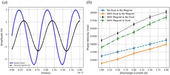
Figure 6(a) represents the typical waveforms of the applied and the received signals of the IAWs. The phase difference and damping are clearly visible from the figure. Figure 6(b) depicts the phase velocity of IAWs observed in a two-electron temperature plasma, which is in the range of $1.38\times 10^4\ {\rm m}\ {\rm s}^{-1}$ to $3.02\times 10^4\ {\rm m}\ {\rm s}^{-1}$
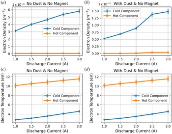
 . The phase velocity appears to grow as the plasma discharge current increases. The temperature and density of electrons rise with the discharge current as portrayed in figure 7. The increase in electron density tends to provide more shielding to the electric field of the ion bunches, but the subsequent increase in electron temperature reduces the shielding effect. As a result, the phase velocity of the wave will increase.
(a) Waveform of applied and received signal of the wave representing the phase difference and damping. (b) Phase Velocity of IAWs at a constant discharge current of $I_{d1}=0.5$ A in cage I and different values of discharge currents $I_{d2}$
 in cage II.

(a,b) Plots of electron densities, and (c,d) plots of electron temperatures at a constant discharge current of $I_{d1}=0.5$ A in cage I, and different values of discharge currents $I_{d2}$
 in cage II for pure plasma and in the presence of dust particles, respectively.

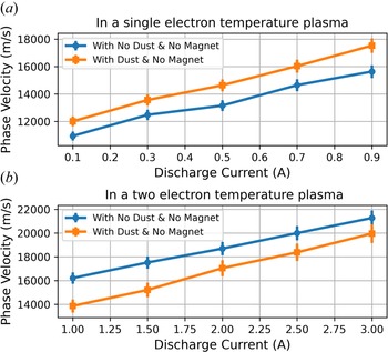
In a single electron temperature plasma, the phase velocity of the IAWs increases in the presence of dust particles due to the attachment of plasma electrons on the dust grains, which is visible in figure 8(a). But in this case, the phase velocity of the IAWs decreases in the presence of dust grains, as shown in figures 6(b) and 8(b). The justification for it is put forward with the help of figure 7. It shows that in the presence of dust grains, there is a significant rise in the density of the cold component of electrons in a two-electron temperature plasma due to the secondary electron emissions from the dust caused by the combination of primary electrons with energy in the range of 60–80 eV, and hot electron group with energy 10–12 eV (Mamun & Shukla Reference Mamun and Shukla2003; Paul et al. Reference Paul, Sharma, Deka, Adhikari, Moulick, Kausik and Saikia2022). Besides this, the electron temperature does not change significantly. Due to the rise in density, the shielding of the electric field associated with the bunching of ions increases, and hence the phase velocity of the wave decreases. Secondary electron emissions can occur in an environment where the hot electron population is high enough with energy above 10 eV. Such electrons can initiate secondary electron emissions by tunnelling through the dust surface. These electrons lost a part of their energy on striking the dust grains. The lost energy is spent in exciting the electrons on the dust grains, and consequently electrons are emitted from the dust surface. The energy of these emitted electrons is comparable to that of the cold electrons, which leads to the increase in the population of the lower energy electrons (Chow, Mendis & Rosenberg Reference Chow, Mendis and Rosenberg1993, Reference Chow, Mendis and Rosenberg1994; Paul et al. Reference Paul, Sharma, Deka, Adhikari, Moulick, Kausik and Saikia2022). The arrangement of the magnetic cages has a contribution in the SEE from the dust grains in the present study. Due to the specific arrangement of the two magnetic cages, the magnetic field lines at the periphery of the junction are almost parallel to the axis of the cylindrical chamber. Hence, the magnetic field at the junction confines the electrons in the central region of the plasma. The field also guides the primary electrons from the filaments towards the junction of the two cages. Therefore, the total electron flux increases significantly at the centre, and consequently, the probability of interaction of these energetic electrons with the dust grains increases, which leads to a sufficient number of secondary electrons emitted from the dust grains (Paul et al. Reference Paul, Sharma, Deka, Adhikari, Moulick, Kausik and Saikia2022).
(a) Phase Velocity of IAWs in a single electron temperature plasma with discharge currents, and (b) phase velocity of IAWs in a two electron temperature plasma for a constant discharge current of $I_{d1}=0.5$ A in cage I and different values of discharge currents $I_{d2}$
 in cage II.

The secondary electron emissions from the dust grains can also be observed from the I–V curves (taken with cylindrical Langmuir probe) shown in figure 9. Under normal circumstances, the electron saturation current to the probe drops in the presence of dust grains, indicating that electrons are attached to the dust grains. The electron saturation current can increase only when there are additional electrons in the plasma. The only possible source of these additional electrons, at fixed plasma conditions, is the secondary emissions from the surface of dust grains. Thus, the study of IAWs can be considered as an alternative method for the confirmation of secondary electron emissions from the dust grains in a two-electron temperature plasma that contains high-energetic electrons above 10 eV as we stated in the beginning.
Langmuir probe I–V characteristics of plasma at a discharge current of $I_{d1}=0.5$ A in cage I, and $I_{d2} = 2.0$
 A in cage II.

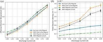
In the presence of an external magnetic field, the electrons participating in the propagation of IAWs may undergo two types of motions depending on the direction of electron velocity: (a) cyclotron motion about the field direction; and (b) helical motion along the field. The electrons undergoing the cyclotron motion are confined by the magnetic field and are prevented from freely shielding the electric field created by the bunching of ions. Further, the electrons belonging to the helical trajectory are drifted away from the wave direction, which as a consequence reduces the number of electrons participating in the shielding process. This subsequently leads to the increase in the phase velocity of IAWs. The dipole field of the bar magnet has some inhomogeneity in the field strength in the region between the wave launching grid and the detector. The field strength is maximum at the middle of the grid–detector axis and decreases gradually on either side. Therefore, the wave experiences an increasing magnetic field up to the axis of the bar magnet. On the contrary, the field strength decreases from the magnetic axis to the detector. The overall effect of the magnetic field is to restrict the movement of the ions and electrons. But, the presence of inhomogeneity of the magnetic field gives rise to gradient drift of the charged particles in the plasma (Deka et al. Reference Deka, Adhikari, Moulick, Kausik and Saikia2021). The gradient of the magnetic field in the region between the grid and magnetic axis is opposite in direction to that of the field gradient between the magnetic axis and detector, and consequently, the gradient drifts of the charged particles are in different directions in the two regions. Irrespective of the direction of the gradient drifts, there is a net loss of electrons and ions participating in the propagation of the wave. The gradient drift of electrons is much higher than the corresponding drift of ions. Therefore, a greater number of electrons are lost than ions. The decrease in electron density reduces the shielding of the electric field and consequently contributes to the increase in phase velocity of the wave. The effective electron temperature increases only slightly in the presence of the magnetic field, and hence cannot play a significant role in the increase in phase velocity. The facts have been depicted in figures 10(a) and 10(b).
(a) Effective temperature of electrons for constant discharge current of $I_{d1}=0.5$ A in cage I and with a variable discharge current $I_{d2}$
 in cage II for different environments. (b) Total electron density of electrons for constant discharge current of $I_{d1}=0.5$
 A in cage I and with a variable discharge current $I_{d2}$
 in cage II for different scenarios.

On introducing the dust particles into the plasma, the electrons collide with the dust grains under the effect of the magnetic field. In such collisions, three processes may take place: (a) attachment of the electrons on the dust surface; (b) scattering of the electrons from the surface of dust; and (c) secondary electron emissions from the dust grains. Whenever dust grains are inserted into the plasma, the plasma particles interact with them. As a result, the electrons and ions get attached to the dust grains. This process is mainly responsible for the charging of dust grains. The electron attachment on the dust grain will occur even in the presence of a magnetic field. The gyroradius of the electron in this case is greater than the size of the dust particles, which may enhance the scattering of the electrons from the dust and reduce the secondary electron emission from the dust surface by the primary electrons and hot electron component of the plasma. The scattering of the electrons from the dust surface will further lead to two possibilities: (a) instantaneous modification of the gyro-orbit of the charged particle; (b) restriction of the mobility of electrons along the field direction. The density of electrons in the presence of dust and a magnet is higher than in the absence of dust (i.e. magnet alone) due to secondary emissions and scattering. There is no significant change in the effective electron temperature in the presence of dust and magnet as depicted in figure 10(a). Therefore, this increase in electron density enhances the shielding of the electric field of ion bunches and, hence, the phase velocity decreases.
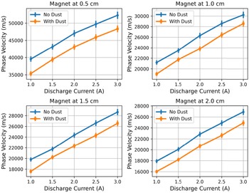
The phase velocity of IAWs as a function of the discharge current at various magnet positions is depicted in figure 11. It indicates that the phase velocity increases as the discharge current increases, but reduces when dust grains are present. The reason is identical to the one mentioned in the preceding paragraph. It also depicts how the wave phase velocity drop as the magnet is farther away. The strength of the magnetic field at the centre of the plasma column decreases on moving the magnet away from the grid–detector axis. Because of this, the restriction on the movement of the electrons decreases, and the electron density also increases. Consequently, the shielding of the electric field increases, which causes the phase velocity of the wave to decrease. The inhomogeneity of the magnetic field decreases on moving the bar magnet away from the grid–detector axis, which reduces the grad-B drift velocity of the charged particles, and consequently, the phase velocity of IAWs decreases. In this way, the field inhomogeneity contributes towards the phase velocity with magnet position.
Phase velocity of IAWs at different magnet positions with a constant discharge current of $I_{d1}=0.5$ A in cage I and different values of discharge currents in cage II.

3.2. Damping study of IAWs
The damping of the IAWs can be attributed to either wave–particle interaction known as Landau damping or due to the collision of particles in plasma. Landau damping is dominant in a plasma with ion temperature almost equal to the electron temperature, i.e. $T_i \sim T_e$ (Hosseini Jenab et al. Reference Hosseini Jenab, Kourakis and Abbasi2011). In the present study, $T_e \gg T_i$
 , so the damping of the wave is collisional. The collisional damping of the IAWs mainly arises from (i) electron–ion, (ii) ion–ion and (iii) ion–neutral collisions (Andersen et al. Reference Andersen, D'Angelo, Jensen, Michelsen and Nielsen1968; Buti Reference Buti1968). In the presence of dust grains, the ion–dust collisions are crucial in the damping of the wave (Nakamura & Bailung Reference Nakamura and Bailung1999).
Figure 12 shows the relative amplitude of the received signal with discharge current. The amplitude of the received signal is normalized by the amplitude of the applied signal. The figure portrays that the damping of the wave decreases with the increase of discharge current. The plasma discharge current increases due to more and more ionization, which causes the neutral density to decrease at a constant pressure. It reduces the collision frequency of ions and electrons with the neutral background. So, the temperature of the ions and the electrons should increase. From the experimental data, it has been observed that the electron temperature increases with the discharge current. Following the same justification, it may be assumed that ion temperature will also increase slightly. As the electron and ion temperature rises, the electron–ion and ion–ion collisions (coulomb collision) will reduce. Hence, the collisions responsible for the damping of the IAWs will decrease, and consequently, the damping will be less.
Relative wave amplitude of received signal as a function of discharge currents $I_{d2}$ in cage II at a constant discharge current of $I_{d1}=0.5 A$
 in cage I.

The damping of the wave will further enhance when dust grains are introduced into the plasma. This additional damping can be attributed to ion–dust collisions. On placing the external magnetic field in the absence of the dust grains, the damping of the wave reduces significantly. The curvature of the charged particle cannot affect the electron–ion collisions if the Larmor radius of electrons ($r_{\rm Le}$ ) is approximately equal to the Debye length (${\lambda }_D$
 ), and the electron cyclotron frequency ($\varOmega _e$
 ) is of the order of the electron plasma frequency ($\omega _e$
 ) (Geller & Weisheit Reference Geller and Weisheit1997). In the present scenario, $r_{\rm Le}\approx {\lambda }_D$
 and ${\varOmega }_e\approx {\omega }_e$
 , which suggest that the magnetic field strength used in this study cannot affect the electron–ion collisions. The gyroradius of the ions ($r_{\rm Li}$
 ) is greater than the electron gyroradius ($r_{\rm Le}$
 ), consequently the curvature of the ion's trajectory is smaller than the electron's trajectory, which should not affect the ion–ion collisions either. On the contrary, the presence of the magnetic field will reduce the ion–neutral collision frequency (Imazu Reference Imazu1981), which in turn reduces the damping of IAWs. Due to the inhomogeneity of the magnetic field, there is a drift of electrons and ions from the plasma that are participating in the propagation of the wave. The grad-B drift velocity of electrons is much larger than the corresponding drift velocity of ions. Therefore, the rate of loss of electrons is much higher than the rate of loss of ions. The ions take away energy from the wave, hence contributing to the damping of the wave. On the other hand, the loss of electrons reduces the electron–ion collisions, which tends to reduce the damping of the wave. The dampening of the wave increases when dust particles are introduced while the magnetic field is still present in the system.
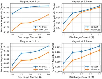
Figure 13 shows the relative wave amplitudes of the received signal for various values of discharge currents at different magnet positions. It appears that the damping decreases with the increase of discharge current, and with the introduction of dust particles, the damping enhances. It also depicts that the damping increases on moving the magnet away from the grid–detector axis. Imazu (Reference Imazu1981) has shown that for magnetic field strength, in the range of 1.5 kG to 0.1 kG, the ion–neutral collision frequency increases almost linearly. The effective field strength for this study varies from 1.43 kG to 0.24 kG, which lies within the range discussed above, consequently the ion–neutral collision increases followed by the damping.
Relative amplitude of wave at different magnet positions as a function of discharge currents $I_{d2}$ in cage II keeping the discharge currents in cage I at a constant value of $I_{d1}=0.5$
 A.

4. Conclusions
The effect of the external magnetic fields on the characteristics of the IAWs in a two-temperature hydrogen plasma has been investigated. The magnetic field has a considerable impact on the propagation and dampening of IAWs.
(1) The presence of a magnetic field in a direction perpendicular to the propagation of IAWs enhances the phase velocity and reduces the damping of the IAWs. The phase velocity increases due to the restriction on the movement of electrons and the reduction of electron density. The electron density decreases because of the diffusion along the field direction. As a result, the electric field generated by the ion bunches is less shielded. The damping is weakened owing to the decrease of ion–neutral collisions in the presence of the magnetic field.
(2) The wave phase velocity is lower in the presence of the magnetic field and dust particles than it is when the magnetic field is present alone, which is due to secondary emissions and scattering of the electrons from the dust grains.
(3) When the magnet is gradually moved away from the grid detector axis, the damping of the waves increases, but the phase velocity decreases. The damping grows as the ion–neutral collisions increase with the lowering of the field strength. On the contrary, the restrictions on the movement of the electrons decrease, and electron density also increases with the reduction of the field strength. Due to this, the shielding of the electric field associated with the ion bunches increases, and consequently, the phase velocity decreases.
(4) When dust particles are introduced in the plasma in the absence of a magnetic field, the phase velocity of the IAWs decreases. The secondary electron emission from the tungsten dust, caused by the energetic group of electrons, in the range of 10–12 eV is responsible for the reduction in velocity. This phenomenon is possible only if there are energetic groups of electrons in the plasma.
(5) The damping of the wave in the presence of dust grains increases for all the plasma environments explored in the present study. This damping is directly associated with ion–dust collisions.
In the presence of the external magnetic field, the ion–neutral collisions seem to be responsible for the change in damping of the wave. Therefore, from the damping of the IAWs, it may be possible to determine the ion–neutral collision frequency. The study can be used to confirm the secondary emissions of electrons from dust grains in a two-electron temperature plasma. The results of this study will be helpful for using IAWs as a diagnostic tool for probing plasma parameters in the presence of a magnetic field. It is worth mentioning that the results obtained are independent of the present experimental set-up. Such observations can be replicated in any experimental system containing two-electron groups with different energies. The next step of the study will be to create a theoretical model to determine the dispersion relation of the IAWs and eventually describe the current findings.
Acknowledgements
The authors would like to thank Mr G.D. Sarma, and Mr S. Zaman for their technical help during the experiment.
Editor E. Thomas, Jr. thanks the referees for their advice in evaluating this article.
Declaration of interest
The authors report no conflict of interest.
Funding
This research received no specific grant from any funding agency, commercial or not-for-profit sectors.
Data availability statement
The data that support the findings of this study are available from the corresponding author upon reasonable request.