I. INTRODUCTION
Rechargeable lithium-ion batteries have been the most widely used batteries in the portable electronics market for many years. Although carbon-based materials are the accepted anode used in the majority of commercial lithium-ion batteries so far, various new higher capacity anode materials are still required to meet increasing energy demands, such as for electric and hybrid electric vehicles.
Recently, transition metal oxides (MxOy, where M is Co, Ni, Cu, or Fe) have shown a number of desirable properties, such as high theoretical capacity (500–1000 mAh·g−1 compared with 372 mAh·g−1 for conventional graphite), on the basis of a novel conversion mechanism.Reference Taberna, Mitra, Poizot, Simon and Tarascon1–Reference Chou, Wang, Liu and Dou4 The new mechanism can be written as MxOy + 2yLi ↔ yLi2O + xM. During the discharge, the MxOy particles are disintegrated into highly dispersed metallic nanoparticles, consisting of M and Li2O matrix, and then the highly divided, high surface energy nature of the nanoparticles facilitates the back reaction with oxygen from the lithium oxide matrix to reform the metal oxide on charge.Reference Poizot, Laruelle, Grugeon, Dupont and Tarascon5 Although the transition metal oxides are attractive, there are still obstacles to their commercial application. One of the most critical problems is their poor cycling performance, resulting from large volume expansion and contraction during the Li+ insertion and extraction reactions, respectively, resulting in the aggregation of small particles into large particles in the host matrix.Reference Zhang, Wu, Hu, Guo and Wan6–Reference Courtney, McKinnon and Dahn8 Thus, the electrode suffers from pulverization, as well as from consequent loss of electrode interparticle contact.
It has been widely demonstrated that to overcome the volume changes during the Li+ insertion and extraction reactions, it is necessary to embed the active materials in a cushioning medium, which maintains particle connectivity. The well-known media for this purpose are amorphous carbon or conducting polymers.Reference Huang, Tu, Zhang, Chen, Yuan and Wu9–Reference Huang, Tu, Xia, Wang and Xiang12 The carbon or conducting polymer medium serves multiple purposes in the composite when it is used in anode.Reference Yuan, Wang, Chew, Chen, Guo, Zhao, Konstantinov and Liu10, Reference Chew, Guo, Wang, Chen, Munroe, Ng, Zhao and Liu13 It serves as (i) an electrically conducting agent to improve the conductivity of the electrode, (ii) a diluting agent to prevent particles from aggregating, and (iii) an efficient matrix to protect the electrode from cracking and pulverization. Recently, conducting polypyrrole (PPy) has been studied as an additive to improve the performance of cathode and anode materials in lithium-ion batteries.Reference Wang, Chen, Konstantinov, Zhao, Ng, Wang, Guo and Liu14–Reference Guo, Wang, Liu and Dou17 However, using PPy powder as an additive in transition metal oxide anode materials for lithium-ion batteries has not been explored. In this study, nickel oxide (NiO)–PPy composite was synthesized and evaluated as an anode material. The conducting PPy was used as a cushioning medium and an electrically conducting agent to improve the cycling performance of NiO in lithium-ion batteries.
II. EXPERIMENTAL
Nanocrystalline NiO powders were synthesized by a spray pyrolysis method.Reference Ng, Wang, Wexler, Konstantinov, Guo and Liu11 Aqueous solution (0.2 M) of nickel nitrate hexahydrate ((Ni(NO3)2?6H2O, ≥97.0%, Sigma-Aldrich, St. Louis, MO) was used as the precursor. The solution was peristaltically pumped into a three-zone spray pyrolysis furnace. This procedure was carried out at an operating temperature of 600 °C using compressed air as the carrier gas. Then, the powder was separated from the hot gas stream via a collecting jar and collected into an airtight sample bottle.
NiO–PPy composite was prepared using a chemical polymerization method. FeCl3 was used as the oxidant and sodium p-toluenesulfonate (NaPTS) as the dopant. The molar ratio of monomer pyrrole to dopant and pyrrole to oxidant was 3:1 and 1:3, respectively. NiO was dispersed into a solution of pyrrole, Triton-X, and NaPTS and exposed to ultrasonic vibrations for 1 h. Then, FeCl3 was slowly added to the suspension and stirred overnight to complete the polymerization. The resulting NiO–PPy precipitate was filtered and washed with distilled water several times. The final product was dried at 50 °C under vacuum for 12 h.
The crystalline phases of NiO and NiO–PPy were examined by x-ray powder diffraction (XRD; GBC Difftech XRD-MMA, USA) using Cu Kα radiation at 40 kV and 25 mA. Raman spectra were collected using a JOBIN YVON HR800 Confocal Raman system (HORIBA Ltd., France) with 632.8-nm diode laser excitation on a 300 lines/mm grating at room temperature. The specific surface areas of the NiO and NiO–PPy powders were measured by nitrogen adsorption according to the Brunauer–Emmett–Teller (BET) method with a NOVA 1000 high-speed gas sorption instrument (Quantachrome Instruments, USA). Scanning electron microscopy (SEM) with energy dispersive spectroscopy (EDS) mapping and field-emission SEM (FESEM) were performed using JEOL JEM-3000 and JEOL JSM-7500FA instruments (JEOL Ltd., Japan), respectively. The amounts of PPy in the samples were estimated using a Mettler–Toledo thermogravimetric analysis/differential scanning calorimetry (TGA/DSC 1) equipped with the STARe System from room temperature to 1000 °C at 10 °C·min−1.
The working electrodes were fabricated by mixing 80 wt% active material, 10 wt% carbon black, and 10 wt% polyvinylidene fluoride with N-methyl-2-pyrrolidinone. The slurry was pasted onto the copper foil substrates and dried under vacuum. Then, the electrodes were pressed and cut to a size of 1 cm × 1 cm. Coin cells (CR2032) were assembled using lithium metal foil as the counter electrode in an argon-filled glove box. The electrolyte solution was 1 M LiPF6 in 1:2 v/v ethylene carbonate:diethyl carbonate. Constant-current charge–discharge tests were performed in the range of 3.00–0.01 V at a current density of 100 mA·g−1. Electrochemical impedance spectroscopy (EIS) was conducted in the frequency range between 0.01 Hz and 100 kHz. Cyclic voltammetry was carried out using a CHI 660B electrochemical workstation instrument (Shanghai Chenhua Apparatus, China) at a scanning rate of 0.1 mV·s−1.
III. RESULTS AND DISCUSSION
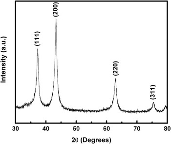
Figure 1 shows the XRD pattern for the nanocrystalline NiO powder. The characteristic peaks of NiO correspond well with standard crystallographic data (JCPDS-No 04-0835). The structure is a nanocrystalline cubic structure with diffraction peaks at 37.46°, 43.44°, 63.08°, and 75.72° [(111), (200), (220), and (311) reflections, respectively]. The average crystal size of the NiO powder was calculated from the largest diffraction peak (200) using Scherrer’s equation, and the estimated crystal size was about 3 nm.
X-ray diffraction pattern of nickel oxide (NiO) powder.

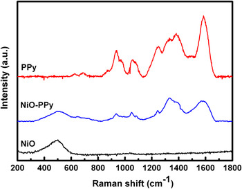
Figure 2 presents the Raman spectrum of the NiO–PPy nanoparticles obtained with 632.8-nm diode laser excitation on a 300 lines/mm grating at room temperature. The peak at ~500 cm−1 is typical of NiO, and the peaks between 800 and 1700 cm−1 match up with the Raman spectrum of pure PPy nanoparticles. The peak at about 1085 cm−1is attributed to the N–H in-plane deformation, and the peaks at about 1375 and 1599 cm−1 are attributed to the ring stretching and the backbone stretching of the C = C bonds of PPy, respectively.Reference Liu, Hwang, Jian and Santhanan18 This indicates that the NiO–PPy composite was successfully synthesized by a simple chemical polymerization method, with the PPy coated on the surfaces of the NiO particles. This result has been further confirmed by FESEM and SEM–EDS.
Raman spectra of NiO, NiO–polypyrrole (PPy), and PPy particles.

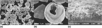
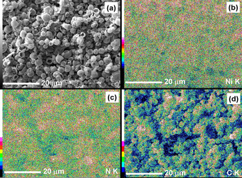
Figure 3 presents the FESEM images of the NiO–PPy composite. The NiO particles are mainly spherical agglomerates with sizes in the range of 2–4 μm [Fig. 3(a)], which is a typical structure for products from the spray pyrolysis method. From the broken spherical particles, we found that the NiO particles are spherical hollow balls with a wall thickness of 200 nm. It has been reported that the specific surface area of NiO prepared by the spray pyrolysis method is larger than that prepared by other methods.Reference Zhong, Wang, Chou, Konstantinov, Rahman and Liu19 The spherical agglomerated structure of NiO exhibits a remarkably high BET surface area of 15.8 m2·g−1. The NiO–PPy composite was synthesized using an in situ chemical polymerization method. NiO was dispersed into a solution of pyrrole and NaPTS and then FeCl3 was slowly added to the suspension to complete the polymerization. The thickness and uniformity of the PPy layer depends on the surface area of the suspended NiO particles. A thinner and more uniform PPy coating layer can be easily formed on the larger BET area of the suspended NiO particles. The PPy layer is about 50-nm thick with the typical PPy cauliflower morphology [Figs. 3(b) and 3(c)].Reference Nishio, Fujimoto, Ando, Ono and Murayama20 From Fig. 3(c), it can be seen that the spherical hollow balls of NiO consist of small spherical particles with sizes less than 10 nm. To verify that the PPy is uniformly coated on the NiO particles, EDS mapping analysis was used (Fig. 4). Both the blue and the red dots in Fig. 4(b) represent the element Ni, with the red dots indicating higher intensity. The dark green dots and the light green dots represent the element N [Fig. 4(c)] and the element C [Fig. 4(d)], respectively, in which the N and C are elements of the PPy. The results show that the N and C are distributed uniformly throughout the whole area, which indicates that the nanosized PPy particles have uniformly coated the surface of the NiO powder.
Field-emission scanning electron microscopy images of NiO–PPy composite.

Scanning electron microscopy (SEM) images of (a) the NiO–PPy composite, with corresponding energy dispersive spectroscopy maps for elements (b) Ni, (c) N, and (d) C.

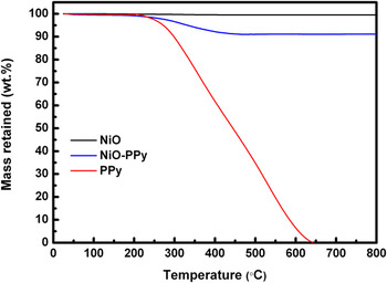
For quantifying the amount of PPy in the NiO–PPy composite materials, TGA analysis was carried out in air. Figure 5 shows the TGA analysis of the NiO–PPy composite along with bare NiO and PPy powders. As can be seen from Fig. 5, the bare PPy powder burns off at 640 °C, whereas the bare NiO powder remains stable over the temperature range used for this experiment. It can also be seen that the composite shows weight loss over the temperature of 200 °C, which corresponds to the oxidation of PPy. There is no further weight change in the composite after the initial oxidation of PPy. Therefore, the change in weight before and after the oxidation of PPy directly translates into the amount of PPy in the NiO–PPy composite. It was found that the amount of PPy in the composite was about 8.08 wt%.
Thermogravimetric analysis curves of NiO–PPy composite, bare NiO powder, and bare PPy powder.

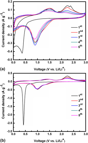
Figure 6 shows the cyclic voltammograms of the NiO and NiO–PPy electrodes. Both samples exhibit similar curves, as reported previously.Reference Varghese, Reddy, Zhu, Chang, Teo, Subba Rao, Chowdari, Shen Wee, Chwee and Sow2, Reference Rahman, Chou, Zhong, Wang, Wexler and Liu21 For the first cathodic process, high intensity peaks are located at about 0.3 and 0.4 V for the NiO and NiO–PPy electrodes, respectively, corresponding to the decomposition of NiO into Ni, formation of amorphous Li2O, and formation of the solid electrolyte interphase (SEI).Reference Rahman, Chou, Zhong, Wang, Wexler and Liu21 This peak shifts to 0.9 V for the NiO electrode and 1.0 V for the NiO–PPy electrode in the subsequent process. However, a low-density peak at around 1.3 V is observed for the NiO–PPy electrode, which could be attributed to the reduction of NiO to metallic Ni and the formation of the SEI layer.Reference Huang, Tu, Xia, Wang, Xiang, Zhang and Zhou22, Reference Grugeon, Laruelle, Herrera-Urbina, Dupont, Poizot and Tarascon23 In the anodic process, two oxidation peaks at about 1.4 and 2.3 V for the NiO and the NiO–PPy composite were observed. These peaks can be attributed to the decomposition of the SEI and Li2O, respectively.Reference Grugeon, Laruelle, Herrera-Urbina, Dupont, Poizot and Tarascon23 The separation between the reduction and oxidation peaks of the NiO–PPy is decreased as compared with the NiO in subsequent cycles, demonstrative of weaker polarization and better reversibility. This is because the high electronic conductivity of the PPy in the composite is beneficial for the diffusion of lithium ions.Reference Huang, Tu, Zhang and Xiang24 No additional peak was found during the redox reactions for the NiO–PPy composite, indicating that the PPy did not contribute any capacity in the charge–discharge process and only acted as a conductive additive.Reference Yuan, Wang, Chew, Chen, Guo, Zhao, Konstantinov and Liu10
Cyclic voltammograms of (a) NiO and (b) NiO–PPy electrodes measured between 0 and 3 V at the scan rate of 0.1 mV·s−1.

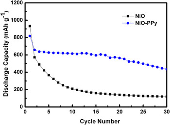
The discharge capacity versus the cycle number for cells with the NiO and NiO–PPy electrodes is presented in Fig. 7. It can be seen that the composite electrode shows a better cycling performance than the NiO electrode. The initial reversible capacity of the NiO electrode was 571 mAh·g−1, and the capacity was reduced rapidly within 10 cycles. After 30 cycles, the capacity was only 119 mAh·g−1. However, the electrode prepared from NiO–PPy composite shows much better capacity retention. The initial reversible capacity was as high as 638 mAh·g−1. The material utilization almost reached 100%, based on the mass of NiO in the composite. Subsequently, the reversible capacity was maintained above 436 mAh·g−1 beyond 30 cycles. The specific capacity retained for the NiO–PPy composite electrode after 30 cycles was 66% compared with 21% for the bare NiO electrode. The improvement in the capacity and the cycling stability of the cell with NiO–PPy composite electrode may be due to the following factors: (i) the conductive PPy coating on the surface of the NiO particles can improve the conductivity of the NiO–PPy electrode, while PPy can also act as a binder, increasing the contact between the particles; (ii) the conducting PPy serves as a diluting agent to prevent nickel regions from aggregating; and (iii) the PPy can act as a cushioning medium that can accommodate the volume changes via the polymer viscoelasticity during the cycling process,Reference Huang, Tu, Xia, Wang and Xiang12 and consequently, the PPy host matrix can prevent cracking and pulverization of the NiO electrode.
Discharge capacity of NiO and NiO–PPy electrodes as a function of the cycle number.

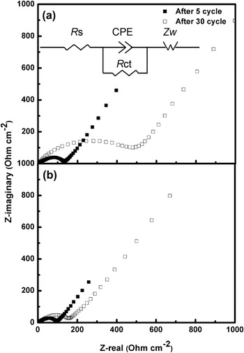
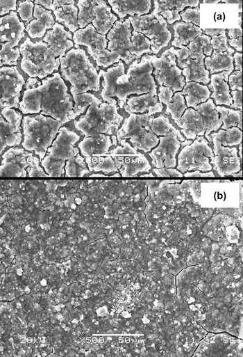
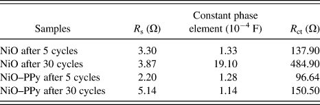
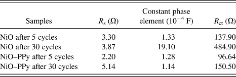
To verify that the PPy coating is responsible for the good performance of the NiO–PPy electrode in the cell, EIS measurements were performed. The Nyquist plots obtained for the nanocrystalline NiO and the nanocomposite electrodes after 5 and 30 cycles are compared in Fig. 8. The thickness of the electrodes was controlled at 50 μm and the coated area of the electrodes at 1 cm2. Impedance of the anode in the Li-ion cell depends strongly on the lithium content inside the electrode. To maintain uniformity, EIS experiments were performed at 2.25 V in the charged state. According to the experimental results obtained in this work, an equivalent circuit, shown as the inset in Fig. 8, is proposed to fit the impedance spectra during the charge process. The equivalent circuit model includes electrolyte resistance (R s), a constant phase element (CPE), charge transfer resistance (R ct), and the Warburg impedance (Z w). The values of the parameters from the impedance data are summarized in Table I. The impedance response exhibits a semicircular loop in the medium frequency region. The diameter of this semicircle gives the charge-transfer resistance (R ct), which is a measure of the charge-transfer kinetics.Reference Veeraraghavan, Paul, Haran and Popov25 We found that the diameter of the semicircle in the medium frequency region for the NiO–PPy composite is smaller than for the NiO cells after 5 and 30 cycles. The reduction in the diameter of the semicircle for the composite could be attributed to a decrease in the interparticle contact resistance.Reference Ng, Wang, Konstantinov, Wexler, Chen and Liu26, Reference Fan and Fedkiw27 It should also be noted that the CPE is constant for the NiO–PPy electrode after 5 and 30 cycles, suggesting that a compact and chemically/mechanically stable film forms on the SEI layer.Reference Aifantis, Brutti, Hackney, Sarakonsri and Scrosati28 This result has been confirmed from the SEM images (Fig. 9). The morphology of the NiO electrode [Fig. 9(a)] shows large cracks when compared to the NiO–PPy electrode [Fig. 9(b)]. These SEM images were captured after the cells completed their 30th cycle of discharge/charge.
Impedance plots of (a) NiO and (b) NiO–PPy electrodes after 5 and 30 cycles. Inset: Equivalent circuit for NiO and NiO–PPy electrodes, which is explained in the text.

SEM images of (a) NiO and (b) NiO–PPy electrodes after 30 cycles.

Various impedance parameters of nickel oxide (NiO) and NiO–polypyrrole (PPy) electrodes after 5 and 30 cycles.
IV. CONCLUSIONS
Hollow spherical NiO powders were prepared by the spray pyrolysis method, and then a NiO–PPy nanocomposite was successfully prepared using a simple in situ chemical polymerization method. The nanosized PPy, with a cauliflower-like morphology, formed a coating on the surface of the NiO. The PPy serves multiple purposes in the composite when it is used in a lithium cell: as a conducting medium, binder, diluting agent, and cushioning medium to protect the electrode from pulverization during electrochemical reactions. Capacities and cycle lives obtained from the cells constructed from NiO–PPy composite are much better than those from cells constructed using pure NiO. The use of PPy and other conducting polymers to improve battery performance can be extended to other electrode materials, especially for materials that suffer from low conductivity and large volume changes during repeated charging and discharging.
ACKNOWLEDGMENTS
Financial support provided by the Australian Research Council (ARC) through ARC Centre of Excellence funding and an ARC Discovery Project (DP 0987805) is gratefully acknowledged. Nurul H. Idris acknowledges the Ministry of Higher Education of Malaysia for a PhD scholarship. Technical assistance on the SEM measurements provided by Mr. Darren Attard is highly appreciated. The authors also thank Dr. Tania Silver for critical reading of the manuscript.