I. INTRODUCTION
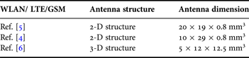
Owing to the rapidly growing demand for multiple services in a mobile terminal and high-speed interconnection among consumer electronic devices, various antennas for universal serial bus (USB) dongle application have been introduced [1]. To provide multi-band internal antennas for mobile wireless communication systems such as the global system for mobile communication (GSM) and digital communication system (DCS) as the second generation cellular system, a variety of antenna designs based on the monopole antenna have been reported [Reference Park and Choi2–Reference Ban, Chen, Sun, Li and Guo4]. Also, the third and fourth generation Wi-Fi/Wi-MAX, LTE operations call for new antenna designs for modern applications [Reference Chen, Lee and Chen5–Reference Pazin, Telzhensky and Leviatan7]. To provide additional functions such as plug-and-play, the conventional USB dongle is used in laptops, portable multimedia players (PMPs), and personal digital assistants (PDA) [Reference Ban, Chen, Sun, Li and Guo4]. Owing to the rapidly growing demands for multiple services in a mobile terminal as shown in Table 1, various multiband antennas for USB dongle applications have been introduced [Reference Ban, Chen, Sun, Li and Guo4–Reference Gong, Jiao, Wang, Li and Zhao6].
Antenna dimensions of typical WLAN laptop computer antennas in recent article (length, width, and thickness).
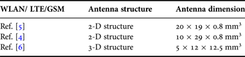
Most of these designs generally require complicated two- or three-dimensional antenna configurations. As a result, it provides not only a large size in the radiator in wireless USB dongle devices or mobile but also some of these complicated antennas cannot cover all the required frequency bands. In addition, these antennas may need a complicated fabrication process as shown in Table 1.
However, these antennas are not suitable for USB dongle applications because of their large volumes and ground sizes, which cannot be incorporated within the limited space that is available for USB dongle applications.
Most of recent papers based on a great amount of scientific work, challenge the traditional scientific point of view which establishes the thermal effects of electromagnetic radiations as the concern for the human health damage. With more than 2 billion portable handsets worldwide, this equipment is of great concern because it is used very close to the head or other parts of the body. The key to the potential risk of using a mobile phone terminal is the specific absorption rate (SAR) of EM energy that it generates on the head. In order to limit the biological effects resulting from exposure to radio frequency (RF) radiation, safety limits are usually defined in terms of the SAR. The IEEE C95.1:2005 standard defines the SAR limit to be 2 W/kg in a 10 g averaging mass [8].
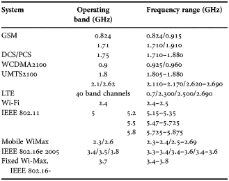
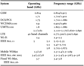
In this paper, a low SAR simple monopole antenna with a meander shape-strip on the other side of the substrate is proposed for wireless communication applications. The proposed antenna has a simple structure, enough bandwidth to cover most future wireless communication services and compact volume which is suitable for fitting in either USB dongle applications or mobile handset. The proposed antenna satisfies voltage standing wave ration VSWR 1:3 requirements [Reference Wong, Chang and Chen9–Reference Chang and Liao11] for wireless broadband GSM, most of LTE bands, WiBro, wireless local area network WLAN, and world interoperability for microwave access Wi-MAX as shown in Table 2. The table shows that the proposed antenna which satisfies VSWR standard operates at most wireless applications. All antenna simulations in free space were carried out using the EM commercial simulator, HFSS ver. 13.0, while, the antenna simulation in the presence of human head was carried out by using CST 2012 human voxel dispersive model.
Operating bands and corresponding frequency range for proposed antenna at standard VSWR (3:1) wireless communications.
II. DESIGN PROCEDURE OF THE PROPOSED ANTENNA
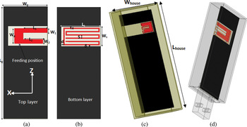
Configuration of the proposed internal monopole antenna is shown in Figs 1(a) and 1(b). The geometry of a printed monopole antenna with polyethylene mobile housing case is shown in Fig. 1(c) while USB housing dongle is shown in Fig. 1(d). The proposed antenna is printed on commercial FR4 substrate with dielectric constant 4.7, and thickness 0.8 mm, and tan δ = 0.02. The antenna dimensions are L 1 = 15 mm, L 2 = 13 mm, W 1 = W 2 = 2 mm, W p = 7 mm, L g = 45 mm, W g = 20 mm, L s = 18 mm, W s = 9 mm, d = 1 mm, S = 1.5 mm, t = 0.5 mm, and δ = 0.5 mm. The mobile substrate has an area of 50 × 85 mm2, on which the antenna dimensions are 18 × 15 mm2 and L housing and W housing are 55 × 90 mm2 however, the USB dongle has an area of 50 × 20 mm2, with same antenna dimensions.
Proposed antenna geometry; (a) upper, (b) bottom layer, (c) mobile handset housing, and (d) USB housing, (the gray layers are metal).

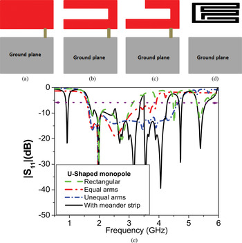
The design starts by the conventional printed rectangular monopole that operates at 2.2 GHz as shown in Fig. 2(a) with offset ground plane 2 mm. The rectangular monopole provides a wide bandwidth. Then, etching a rectangular strip to create U-shaped monopole antenna with equal arms to improve the bandwidth, the response of this design is also shown in Fig. 2(b). This step was carried out to elongate the current path. The longer arm of the U-shaped monopole determines the lower operating frequency. Two unequal arms of a monopole are proposed to provide more bands to the antenna as shown in Fig. 2(c). The shorter arm of the U-shaped monopole should be optimized to create wide bandwidth. Finally, the design ended by adding a bending meander strip on the other side with width 0.5 mm to design a lower resonant frequency as shown in Fig. 2(d). The length of the meander strip line is approximately half wavelength of the operating resonant frequency [Reference Tang, Lin, Chen and Horng12–Reference Ren, Chen and Huang14]. There is slight coupling between meander shape strip and the monopole on the other side. Hence, the position and dimensions of the meander shaped strip should also be optimized to achieve small coupling on the main antenna radiator. |S 11| shows the design steps as shown in Fig. 2(e). Red and black colors represent monopole radiator metal while gray color represents the ground plane.
(a–d) Proposed antenna design steps, and (e) simulated reflection coefficient of the design procedure.

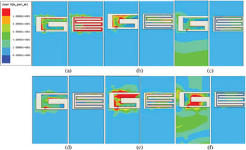
The proposed antenna can be capsulated inside the housing whether mobile or USB dongle to operate as an internal antenna. It achieves wide bandwidths at 1.5 to 3.8 GHz and from 5.2 to 5.5 GHz to cover the operation bands as shown in Table 2 [Reference Ren, Chen and Huang14]. The current distributions at different resonant frequencies at 0.9, 1.5, 1.8, 2.4, 3.5 and 5.2 GHz, respectively are shown in Fig. 3. It shows that each resonant frequency could be controlled through each corresponding there's dimension. The surface current magnitude is high (red colors) around the element with the corresponding resonant frequency that it works for. The surface current magnitude is distributed around the meander strip at 0.9 GHz. The surface current distributions corresponding to resonant frequencies extended from 1.5 to 3.8 GHz and are more affected by unequal arms of the U-shaped monopole antenna with a slight effect of meander strip.
Current distribution for the proposed antenna at (a) 0.9 GHz, (b) 1.5 GHz, (c) 1.8 GHz, (d) 2.4 GHz, (e) 3.5 GHz, and (f) 5.2 GHz.

III. EFFECT OF HEAD MODEL AND SAR CALCULATION
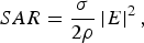
SAR is the basic restriction for EM exposure of a user of a mobile phone and is a fundamental parameter when discussing the health risks of EM power absorption in the body [15]. This quantity is defined as
 $$SAR=\displaystyle{\sigma \over {2\rho }}\left\vert E \right\vert ^2\comma \;$$
where ρ(kg/m3) and σ(S/m) are the body tissue density and conductivity, respectively. E(V/m) is the r.m.s value of electric field strength in the tissue.
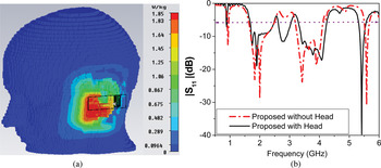
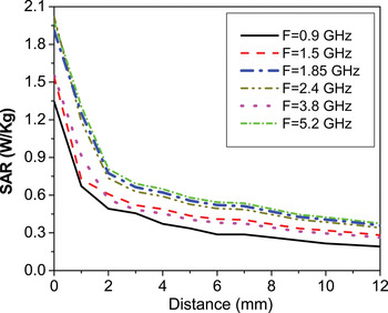
The reflection coefficient response of the proposed antenna in the presence of the human head model is simulated by using the CST microwave studio 2012 Hugo Voxel dispersive model with 1 mm resolution at GSM 1.85 GHz as shown in Fig. 4(a). The r. m. s. reference antenna power is 0.5 W and the distance between the head and the antenna is D = 0.5 mm. The reflection coefficient of the proposed antenna for mobile handset with/without the presence of the head model is shown in Fig. 4(b). It is clearly seen that there is an agreement between the proposed antenna with/without head model with a small shift in resonant frequencies 0.9 and 5.2 GHz and decreasing the amount of power radiated due to the power absorbed by the human head tissues. The 10-g SAR results are illustrated in Table 3, it is clearly seen that the 10-g SAR results at all frequencies meet the SAR limits of 2.0 W/kg standards. The effect of distance at different resonant frequencies on the SAR values is shown in Fig. 5. For example, at 1.85 GHz, the SAR values reduced from 1.85 to 0.31 W/kg when increasing the distance between the proposed antenna and the head model from 0 mm to 12 mm, as shown in Fig. 5. The peak value of SAR is 1.97 W/kg at 5.2 GHz while the minimum value of the SAR is 1.55 at GSM (0.9 GHz). Moreover, mounting this antenna on the backside of handheld devices or profiling these devices might be the simplest way to reduce SAR to lower levels [Reference Watanabe, Nojima and Fujiwara16].
(a) The proposed antenna with the head model at 1.85 GHz. (b) |S 11| of the proposed antenna with/without the head model.

Variation of SAR with distance from the head at different frequencies.

Simulated SAR values of the proposed antenna with 0 mm distance from the head.

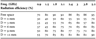
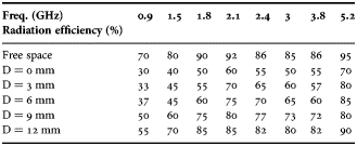
The effect of distance between human head model and antenna D on the antenna radiation efficiency is also studied as shown in Table 3. Table 4 shows that the radiation efficiency is decreased in the presence of human head. At distance D = 0 mm and the lowest frequency 0.9 GHz, the antenna radiation efficiency has the largest reduction than the highest frequency 5.2 GHz. As the distance is increased, radiation efficiency increases until D > 12 mm, the radiation efficiency goes closer to free space efficiency.
Effect of the head model on the radiation efficiency.
The easiest way to reduce the effect of the RF on human tissues is to place the antenna away from the user or in the back of the handset; and then, the average SAR may be reduced. The effect of distance at different resonant frequencies on the SAR values is shown in Fig. 5. For example, at 1.85 GHz, the SAR values reduced from 1.85 to 0.31 W/kg by increasing the distance between the proposed antenna and the head model from 0 to 12 mm, as shown in Fig. 5.
IV. RESULTS AND DISCUSSION
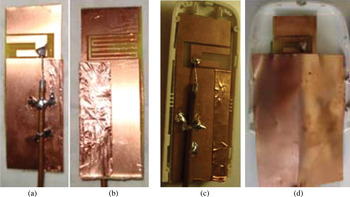
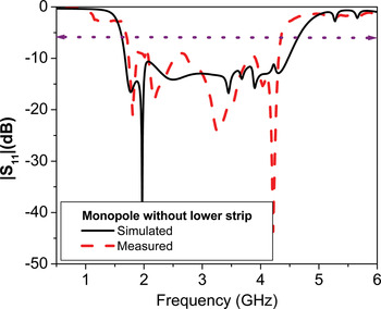
The proposed antenna is fabricated on a 0.8 mm thick FR 4 substrate with a relative dielectric constant of 4.7 and tan δ = 0.02. The proposed antenna uses two separate resonant strips; the main strip is U-shaped monopole antenna with different arm lengths. The second strip is bending meander strip on the other substrate side; the second strip slightly affects the antenna's higher resonant mode, and vice versa. The steps of the reflection coefficient design procedure are shown in Fig. 2(e). This characteristic makes the proposed antenna easy to implement for wireless communication operation. The antenna's excited higher resonant mode can be controlled solely by strip 1, while the lower resonant mode is controlled by strip 2. The two antennas configurations, without lower strip and with lower strip were fabricated by using photolithographic techniques as shown in Fig. 6. The comparison between simulated and measured reflection coefficient of only U-shaped monopole antenna with unequal arms is shown in Fig. 7. The impedance bandwidth is extended from 1.6 up to 4.6 GHz.
The fabricated antenna, (a) monopole antenna without lower strip and (b) monopole antenna with lower strip, (c) USB housing, and (d) mobile housing.

Comparison of simulated and measured reflection coefficient of the proposed antenna without lower strip.

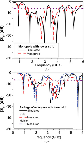
The comparison between simulated and measured reflection coefficient of the monopole antenna with lower meander strip is shown in Fig. 8(a). The lower meander strip is used to create lower resonant frequency and can be controlled by variations of the length of the strip. The effect of USB and mobile handset housings as shown in Figs 1(c) and 1(d) is obtained in Fig. 8(b). The effect of the USB dongle housing on the antenna performance was also studied experimentally. As shown in Fig. 8(b), the effects of the USB dongle on impedance bandwidth are moderate but still cover the proposed bands. The measured and simulated results are in good agreement.
Comparison of simulated and measured reflection coefficient (a) proposed antenna and (b) proposed antenna with USB dongle, housing, and mobile housing.

The measured results show that the −6 dB reflection coefficient bandwidth of the proposed antenna (the impedance bandwidth definition of 3:1 VSWR), at the lower resonant mode reaches 90 MHz (860–950) MHz, while that of the other resonant modes are almost 2.3 GHz (1.5–3.8 GHz). Table 5 shows the simulated and measured antennas parameters, efficiency, gain, and fractional bandwidth. The radiation characteristics of the designed prototype were also studied.
Proposed antenna parameters.

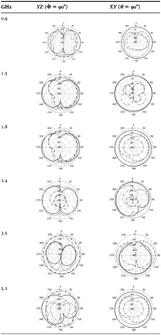
Table 6 plots the measured radiation patterns at 900 MHz, 1.5, 1.8, 2.4, 3.5 and 5.2 GHz, respectively. The radiation mechanism of the monopole antenna can be found in [Reference Balanis17]. Monopole-like radiation patterns are observed, which are broadside radiation pattern similar to those obtained for conventional internal patch antennas for mobile phone applications.
Measured and simulated radiation pattern in YZ and XY planes at resonant frequency of the proposed antenna with main radiator (unequal arms U-shaped monopole) and the meander strip, E Φ: slide lines, E Θ: dotted lines, black represent the simulated results and gray represent the measured data.

V. CONCLUSION
This paper described the design and characteristics of a low SAR internal monopole antenna with simple compact configuration for wireless communication applications. The proposed antenna can be fabricated easily by etching a rectangular monopole antenna with unequal arms U-shaped slot and a meandering strip on the other side on the same board. The antenna has very wide −6 dB reflection coefficient with bandwidth of 2.3 GHz (1.5–3.8 GHz), and bandwidth of 0.3 GHz (5.2–5.5 GHz); in addition, a bandwidth of 90 MHz (860–950 MHz), which easily covers most of the traditional and future services in mobile and laptop computers. Finally, radiation efficiency, SAR, antenna gain, and radiation pattern are found to be acceptable. The proposed antenna is very promising for mobile applications, because it is easily fabricated.
ACKNOWLEDGEMENT
This research is supported by the National Telecommunication Regularity Authority (NTRA), Ministry of Communication and Information Technology, Egypt.
 Dalia M. Elsheakh received the B.S., M.S., and Ph.D. degrees in electrical and communication engineering from Ain Shams University, Cairo, Egypt, in May 1998, September 2004, and October 2010, respectively. Her master's thesis was about the design of microstrip PIFA antennas for mobile handsets. Her Ph.D. dissertation was entitled, “Electromagnetic Band-Gap (EBG) Structure for Microstrip Antenna Systems (Analysis and Design).” From 2008 to 2009, she was Assistant Researcher at the Hawaii Center for Advanced Communications (HCAC), College of Engineering, University of Hawaii at Manoa, Honolulu. She holds one patent, has published 28 papers in peer-refereed journals and 29 papers in international conferences in the area of microstrip antenna design. Her current research interests are in microstrip antennas theory and metamaterials design and electromagnetic wave propagation. She participates in many research projects at the national and international levels as Egypt-NSF-USA joint funds program and the European Committee Programs FP7 program, STDF, and ITIDA-ITAC.
 Esmat A. Abdallah graduated from the Faculty of Engineering and received the M.Sc. and Ph.D. degrees from Cairo University, Giza, Egypt, in 1968, 1972, and 1975, respectively. She was nominated as Assistant Professor, Associate Professor, and Professor in 1975, 1980, and 1985, respectively. She has focused her research on microwave circuits design, planar antenna systems, and nonreciprocal ferrite devices, and recently on EBG structures, ultra-wide bandwidth (UWB) components and antenna and RFID systems. She acts as a single author and as a coauthor on more than 170 research papers in highly cited international journals and in proceedings of international conferences in her field, such as IEEE Trans., Antenna Propagat, and Microwave Theory Tech., etc. She participates in many research projects at the national and international levels as Egypt-NSF-USA joint funds program and the European Committee Programs FP7 program, STDF of Egypt, NTRA etc. She is also a reviewer for many international societies.