1. Introduction
According to a WHO report, almost 15% of the world’s population face some disability [1], which makes one dependent on others in different ways. The disabilities may be by birth or may be due to some accident or stroke. This research area has attracted various researchers’ attention to work in the field to develop prosthetics [Reference Cordella, Ciancio, Sacchetti, Davalli, Cutti, Guglielmelli and Zollo2], extremities [Reference Slavens and Harris3], and rehabilitation devices [Reference Maciejasz, Eschweiler, Gerlach-Hahn, Jansen-Troy and Leonhardt4] with interest in the analysis of human motion behaviour [Reference Kandori, Miyashita, Hosono, Yokoe, Ogata, Abe and Sakoda5–Reference Mesquita, da Fonseca, Pinheiro, Velhote Correia and da Silva7] to mimic the motion for humanoid robots. Because, human structure is a typical example of a mechanism, the study of kinematics and dynamics of mechanism has a remarkable role in analysing human behaviour and prosthetics development. Therefore, kinematic equations generation for analysis is basic and essential to determine system’s dynamic parameters.
A wide range of work has already been carried out in robotics with applications towards rehabilitation and prosthetics. Many researchers have worked for mechanisms with anyone or hybrid of tendon operated [Reference Ozawa, Kobayashi and Hashirii8, Reference Armstrong and Chaffin9], hydraulic [Reference Lee, Baek, Lee, Choi, Moon and Koo10] and pneumatic [Reference Jiang, Xiong, Sun and Xiong11] actuated mechanisms (also soft robotics [Reference Kuhn, Ringwald, Schappler, Johannsmeier and Haddadin12–Reference Majidi Fard Vatan, Nefti-Meziani, Davis, Saffari and El-Hussieny14]) and actuator-based mechanisms [Reference Pandey and Mandal15–Reference Perry, Rosen and Burns17], and their controllers are developed, which is out of the paper’s purview. Computation is one of the essential aspects for analysis is studied in this paper. Computation complexity for generating kinematic and dynamic equations increases with an increase in the degree of freedoms by considering more joints. The complexity may be due to different parameters affecting the kinematic motion, and hence, to simplify the derivation, additional assumptions [Reference Bullock, Borras and Dollar18] are necessary to be made to streamline the kinematic models. As the joint rotation has direct effect on joint forces or torques [Reference Derrick19–Reference Hahn, Olvermann, Richtberg, Seiberl and Schwirtz21], the effective sequence of joint rotations [Reference Derrick, van den Bogert, Cereatti, Dumas, Fantozzi and Leardini6, Reference Oualkacha and Rivest22–Reference Wu and Cavanagh26] and joint rotations as function of time ‘t’ [Reference Boston, Rudy, Mercer and Kubinski27, Reference Borbély and Szolgay28] are equally important. Mathematical expression may be modified [Reference Carpinella, Jonsdottir and Ferrarin29–Reference Braido and Zhang31] to find a close relation to the human motion profile to reduce the complexities in successive derivatives for velocity and acceleration analysis followed by dynamic analysis.
If the mobility (degree of freedom) of the mechanism is increased, this computation complexity increases. Therefore, many researchers have worked on presenting effective algorithms for kinematic analysis. For kinematic modeling, different approaches such as tensor method [Reference Casey and Lam32], matrix approach [Reference Legnani, Casolo, Righettini and Zappa33], and screw theories [Reference Legnani, Casalo, Righettini and Zappa34] are available for serial manipulators, which are further extendable to parallel and hybrid manipulators [Reference Ahmad, Khan and Anderson35]. Researchers have developed programs [Reference Lenarčič and Umek36, Reference Miro and White37] and sometimes used graph theory [Reference Richard, McPhee and Anderson38, Reference Fleischer and Krauße39] for automatically generating kinematic equations using any one of the approaches to ease the simulation of results. Parallel research is conducted in the field of motion capturing systems, sampling, task-based and kinematic matrices for kinematic analysis related to reaching the human upper limb performing daily living activities (ADLs) [Reference Mesquita, da Fonseca, Pinheiro, Velhote Correia and da Silva7, Reference Mesquita, Pinheiro, Velhote Correia and da Silva40]. Because of the desire for coming with mechanisms imitating human motions, the researchers are working for continuous improvement in design and control modalities for upper limb extremities [Reference Gull, Bai and Bak41], accurate shoulder-elbow complex mechanism (tendon operated) [Reference Stanišić and Goehler42], and upper limb (shoulder, elbow and wrist) rehabilitation mechanism [Reference Pang, Wang, Wang, Yu, Sun and Liu43]. Reliability challenges in computational and practical aspects posed during task-based applications can be solved by kinematic representation [Reference Krishnan, Björsell, Gutierrez-Farewik and Smith44], functional principal component analysis (fPCA) [Reference Averta, Della Santina, Valenza, Bicchi and Bianchi45] and optimised trajectory motion [Reference Averta, Della Santina, Valenza, Bicchi and Bianchi45].
These studies attracted the researchers to study grip-release motion for time differences during closing and opening of fingers was studied by [Reference Kandori, Miyashita, Hosono, Yokoe, Ogata, Abe and Sakoda5], develop empirical relations for tendon operated finger movements [Reference Armstrong and Chaffin9] and proposed a calibration procedure through wearable sensors to determine kinematics for shoulder-elbow and trajectory for wrist in agreement with the International Society of Biomechanics (ISB) standards [Reference Picerno, Caliandro, Iacovelli, Simbolotti, Crabolu, Pani, Vannozzi, Reale, Rossini, Padua and Cereatti46]. A five degree of freedom (5-DOF) human arm kinematic chain for robot-assisted rehabilitation therapy devices with inverse-Jaciobian based kinematic algorithm to measure joint rotation for the upper limb using an accelerometer placed on it [Reference Bertomeu-Motos, Lledó, Díez, Catalan, Ezquerro and Badesa47, Reference Bertomeu-Motos, Blanco, Badesa, Barios, Zollo and Garcia-Aracil48]. Forward and inverse kinematic analysis for 7-DOF exoskeleton human upper limb with a tilted base axis [Reference Loh and Rosen49] and 5-DOF upper-limbed rehabilitation robot was carried out using D-H parameters and ADAMS software [Reference Wang, Cai, Cui and Pang50] for kinematic analysis and simulation. Kinematic analysis and mechanism synthesis using the Bond Graph approach [Reference Vaz, Kansal and Singla51–Reference Romero, Félez, Martínez and Maroto53], and Clifford algebra and Lie algebra [Reference Simo-Serra, Perez-Gracia, Moon and Robson54] were used to kinematically analyse task-based multifingered robotic hand with finite and infinitesimal motion.
As the human upper limb has a significant role in performing daily activities (ADLs), it has derived many researchers’ interest in the biomechanics field inclination towards prosthetic, limb extremities, and rehabilitation. A 10 DOF R-type human upper limb is selected for kinematic analysis to verify the proposed matrix approach. The multiaxial ball and socket type of shoulder joint (glenohumeral joint) is replaced by 2-DOF revolute joint capable of producing almost all desired movements. Because of ulna and radial arrangement, the elbow joint’s complicated design is replaced by a 2-DOF revolute joint capable of producing flexion-extension and pronation-supination movements. The wrist joint, a combination of different carpal bones, is replaced by a 2-DOF revolute joint capable of producing flexion-extension and ulnar and radial deviations. The palm is assumed to be attached to the wrist and serves as a platform for the 4-DOF fingers with two DOF for metacarpophalangeal (mcp) and one DOF each for proximal interphalangeal (pip) and distal interphalangeal (dip) joints, respectively. The operations of all fingers are nearly symmetrical, and therefore, only one finger at the wrist is considered for simplicity.
Because, the complexity increases with increasing mobility and workspace, the paper aims to find the correlations for kinematic parameters of two consecutive link. The matrix approach is with D-H parameters for generating kinematic equations for direct kinematic analysis using the MATLAB program module. Mathematical expressions are derived for kinematic analysis for determining kinematic parameters such as joint positions, velocities and accelerations using the matrix approach. This matrix approach is based on Euler angles defined by a sequence involving several reference frames due to successive rotations. Further, the different expressions in the developed model for position, velocity and accelerations are justified graphically for consecutive links of a serial manipulator with n-links. This approach is used to determine different kinematic parameters with their gradient variation for the human upper limb with 10-DOF. The research is motivated by the work carried out by researchers in the field of modeling and defining some parametric relations based on case studies.
2. Modeling for Kinematic Parameters
Once a mechanism is decided while designing the mechanism, the kinematic analysis is very important for further analysis of mechanisms, that is, dynamic analysis for selectin of appropriate actuators. This section aims to derive a mathematical model for kinematic analysis to determine the final position, velocity and accelerations of the end-effectors in subsequent subsections.
2.1 Relation between velocities of two consecutive links
The range of motions may be decided by the synthesis of mechanisms, which is out of this paper’s scope. The values of the angle of rotations are selected from the available literature. Position analysis of i th joint (P i ) is determined by multiplying the composite matrix (C) with the initial position (P o ) of the mechanism. The composite matrix (C) is calculated by multiplying series of transformation matrices after rotational motions.
 \begin{align}{P_i} = {}^0{C_i} \times {P_0}.\end{align}
A composite matrix for i th link can be used as a product of the composite matrix of (i−1)th link and transformation matrix of i th link. The mathematical expression for the relation between two consecutive links is given below.
 \begin{align}{}^0{C_i} = {}^0{C_{i - 1}} \times {R_{z, \pm \frac{\pi }{2}}} \times {}^{i - 1}{R_i},\end{align}
where
 ${R_{z, \pm \frac{\pi }{2}}}$
is the transformation matrix applicable to any rotation of plane due to change in axis of rotation by considering
 $\frac{\pi }{2}$
angle of rotation about z axis. The relation between the angular deflections (or rotations) of i th and (i−1)th link, considering rotation about z axis only of i th link is given by
 \begin{align}{\theta _i} = {\theta _{i - 1}} + {R_{z, \pm \frac{\pi }{2}}} \times {}^{i - 1}{\theta _{iz}}.\end{align}
Equations and are used as input for linear velocity relation. Linear velocity matrix for i th link is calculated as the first time derivative of the equation and is given as
 \begin{align}{V_i} = \frac{{d{P_i}}}{{dt}} = \frac{{d{}^0{C_i}}}{{dt}} \times {P_0} = {W_i} \times {P_0},\end{align}
Where
 \begin{align}{W_i} = \frac{d}{{dt}}\left( {{}^0{C_{i - 1}} \times {R_{z, \pm \frac{\pi }{2}}} \times {}^{i - 1}{R_i}} \right) = {}^0{C_{i - 1}} \times {R_{z, \pm \frac{\pi }{2}}} \times \frac{{\partial {}^{i - 1}{R_i}}}{{\partial {\theta _i}}} \times \dot{\theta}_i + {W_{i - 1}} \times {R_{z, \pm \frac{\pi }{2}}} \times {}^{i - 1}{R_i}.\end{align}
 \begin{align}\!\!\!\!\!\!\!\!\!\!\!\!\!\!\!\!\!\!\!\textrm{The constituent terms of Eq. (5) can be determined as}\ \frac{{\partial {}^{i - 1}{R_i}}}{{\partial {\theta _i}}} = U \times {}^{i - 1}{R_i},\ \textrm{and}\ {W_{i - 1}} = \frac{{d{}^0{C_{i - 1}}}}{{dt}}\end{align}
 ${\rm{where}}\;{\rm{differentiation}}\;{\rm{compensator}}{\mkern 1mu} (U) = {\rm{ }}{{{d^{i - 1}}{R_i}/d{\theta _i}} \over {^{i - 1}{R_i}}} = \left[ {\matrix{
0 & { - 1} & 0 & 0 \cr
1 & 0 & 0 & 0 \cr
0 & 0 & 0 & 0 \cr
0 & 0 & 0 & 0 \cr } } \right]$
Because the second term (in the equation) will be zero for first link, and the composite matrix up to first link is a unit matrix, the constituting term (W) for first link in velocity term is given by
 \begin{align}{W_1} = \frac{{\partial {}^0{R_1}}}{{\partial {\theta _1}}} \times \dot{\theta}_1 = \left( {U \times {}^0{R_1}} \right) \times \dot{\theta}_1 = {}^0{\omega _1} \times {}^0{R_1},\end{align}
where
 ${\omega _i} = {\rm{ angular velocity}} = {\left( {{\omega _x}\widehat i + {\omega _y}\widehat j + {\omega _z}\widehat k} \right)^T} \times \left( {\widehat i + \widehat j + \widehat k} \right)$
, where i, j and k are unit vectors in x, y and z directions and
 ${\omega _x} = {\omega _y} = 0$
, which can be again written in 4 × 4 angular velocity matrix form as
 $^{i - 1}{\omega _i} = U \times {\dot \theta _i} = \left[ {\matrix{
0 & { - {\omega _i}} & 0 & 0 \cr
{{\omega _i}} & 0 & 0 & 0 \cr
0 & 0 & 0 & 0 \cr
0 & 0 & 0 & 0 \cr } } \right] \times \left[ {\matrix{
{\hat i} \cr
{\hat j} \cr
{\hat k} \cr
1 \cr } } \right]$
Similarly, the linear velocity for i th link (V
i
) can also be written as a product of resultant angular velocity (
 $\omega_{i}$
) and effective length (0
L
i
)
 \begin{align}{V_i} = {}^0{\omega _i} \times {}^0{L_i} = {}^0{\omega _i} \times \left( {{}^0{C_i} \times {P_0}} \right).\end{align}
Comparing equation and the resultant velocity of i th link (0 ω i ) can be determined as
 \begin{align}{}^0{\omega _i} = \frac{{{W_i}}}{{{}^0{C_i}}} = {\omega _{i - 1}} + {R_{z, \pm \frac{\pi }{2}}} \times {}^{i - 1}{\omega _i}.\end{align}
The equation can also be obtained by finding the time derivative of the equation. ω i is a 4 × 4 matrix having resultant angular velocities in all the three axes. However, the angular velocity of any link is considered only in Z axis.
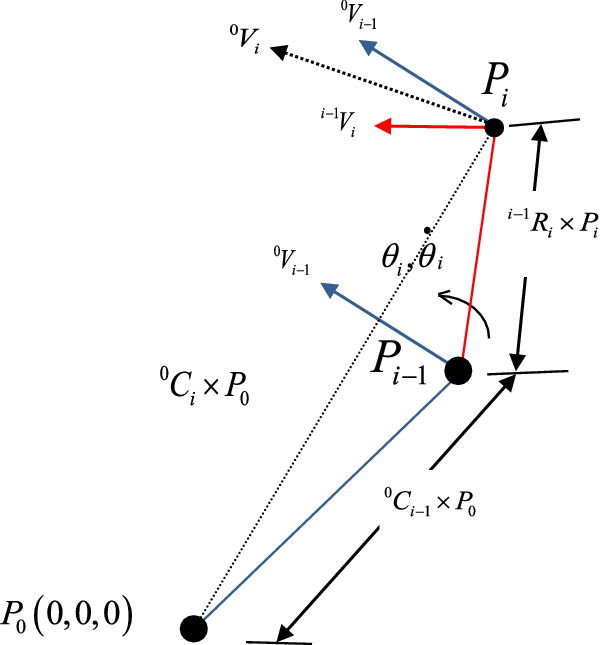
The velocity diagram for the equation is shown in Fig. 1 as expressing the relation between two consecutive links to better understand the terms used. The resultant velocity for i th link is defined as the vector sum of two velocities, that is, resultant velocity of (i−1)th link transformed to i th joint considering i th link stationary, and resultant velocity of i th link considering all other links stationary.
 \begin{align}{}^0{V_i} = {}^0{V_{i - 1}} + {}^{i - 1}{V_i} = \frac{{\partial {}^0{P_i}}}{{\partial {\theta _i}}} \times \dot{\theta}_i + {W_{i - 1}} \times {R_{z, \pm \frac{\pi }{2}}} \times {}^{i - 1}{P_i} = \left( {{}^0{C_i} \times {}^{i - 1}{\omega _i} + {W_{i - 1}} \times {R_{z, \pm \frac{\pi }{2}}} \times {}^{i - 1}{R_i}} \right) \times {P_0},\end{align}
where 0
V
i−1 = the linear velocity at point P
i
due to angular velocities up to (i−1)th joint keeping i th joint stationary,
i−1
V
i
= the linear velocity at point P
i
due to angular velocity up to i th joint keeping remaining joints stationary, and
 $\frac{{\partial {}^{i - 1}{R_i}}}{{\partial {\theta _i}}}$
determines the change in rotation matrix for i th link (at point P
i
) undergoing angular deflection
 $\partial {\theta _i}$
.
Velocity diagram for illustration of velocity relations between two consecutive links.

Position gradient and velocity gradients can further be calculated as
 $\frac{{d{P_i}}}{{d{\theta _i}}} = \frac{{{d^0}{C_i}}}{{d{\theta _i}}} \times {P_0}$
and
 $\frac{{d{V_i}}}{{d{\theta _i}}} = \frac{{d{W_i}}}{{d{\theta _i}}} \times {P_0}$
, which may be required in determining the joint torques.
2.2 Relation between the acceleration of two consecutive links
Resultant acceleration matrix up to i th link is obtained by differentiating twice Eq. (1) and is expressed mathematically as
 \begin{align}{}^0{A_i} = \frac{{{d^2}{P_i}}}{{d{t^2}}} = \frac{{{d^2}{}^0{C_i}}}{{d{t^2}}} \times {P_0} = \frac{{d{W_i}}}{{dt}} \times {P_0} = {A_i} \times {P_0},\end{align}
which gives the expression for
 \begin{align*}{A_i} = {}^0{C_{i - 1}} \times {R_{z, \pm \frac{\pi }{2}}} \times \frac{{d{}^{i - 1}{W_i}}}{{dt}} + {A_{i - 1}} \times {R_{z, \pm \frac{\pi }{2}}} \times {}^{i - 1}{R_i} + 2 \times {W_{i - 1}} \times {R_{z, \pm \frac{\pi }{2}}} \times {}^{i - 1}{W_i},\end{align*}
 \begin{align}{A_i} = \frac{{\partial {P_i}}}{{\partial {\theta _i}}} \times \ddot{\theta}_i + \frac{{\partial {V_i}}}{{\partial {\theta _i}}} \times \dot{\theta}_i + {W_{i - 1}} \times {R_{z, \pm \frac{\pi }{2}}} \times {}^{i - 1}{V_i} + {A_{i - 1}} \times {R_{z, \pm \frac{\pi }{2}}} \times {}^{i - 1}{R_i},\end{align}
where
 $\frac{{{\partial ^2}{}^{i - 1}{R_i}}}{{\partial {\theta ^2}_i}} = {U^2} \times {}^{i - 1}{R_i}$
, and
 ${}^{i - 1}{\alpha _i} = U \times \ddot{\theta}_i $
Now the acceleration equation reduces to
 \begin{align}{}^0{A_i} = {}^0{P_i} \times \left( {{}^{i - 1}{\alpha _i} + {}^{i - 1}\omega _i^2} \right) + {A_{i - 1}} \times {R_{z, \pm \frac{\pi }{2}}} \times {}^{i - 1}{P_i} + 2 \times \left( {{V_{i - 1}} \times {R_{z, \pm \frac{\pi }{2}}} \times {}^{i - 1}{R_i}} \right) \times {}^{i - 1}{\omega _i}\end{align}
or
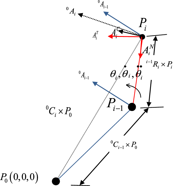
 \begin{align}{}^0{A_i} = \left( {{}^{i - 1}A_i^N + {}^{i - 1}A_i^T} \right) + {}^0{A_{i - 1}} + A_i^C,\end{align}
where the first term responds to the acceleration matrix effect (A i−1) caused at point P i due to angular velocities and angular accelerations upto (i−1)th joint keeping i th joint stationary and second term computes the acceleration effect ( i−1 A i ) caused at point P i due to angular velocity and angular acceleration at i th joint keeping remaining joints stationary. The third term in the equation computes the Coriolis component of acceleration. From the equation, we can define the linear acceleration for first link can be calculated as equation, which contains only radial and the tangential component of rotation.
 \begin{align}{}^0{A_1} = \frac{{\partial {}^0{R_1}}}{{\partial {\theta _1}}} \times \ddot{\theta}_1 \times {P_0} + \frac{{{\partial ^2}{}^0{R_1}}}{{\partial \theta _1^2}} \times \dot{\theta}^{2}_1 \times {P_0} = U \times {}^0{R_1} \times \left( \ddot{\theta}_1 + U \times \dot{\theta}^{2}_1 \right) \times {P_0}\end{align}
The resultant angular acceleration matrix can be calculated as
 ${}^0{\alpha _i} = \frac{{{A_i}}}{{{}^0{C_i}}}$
, which is a combination of acceleration angles (
 ${\alpha _i} = \frac{{d{\omega _i}}}{{dt}} = {\alpha _{i - 1}} + {R_{z, \pm \frac{\pi }{2}}} \times {}^{i - 1}{\alpha _{iz}}$
), square of velocities (
 ${}^0\omega _i^2 = \frac{{{W_i}}}{{{}^0{C_i}}} = \omega _{i - 1}^2 + {R_{z, \pm \frac{\pi }{2}}} \times {}^{i - 1}\omega _i^2$
) and effective Coriolis component due to velocities of all links up to that joint. Figure 2 represents the different acceleration components of the equation.
Acceleration diagram for illustration of acceleration relations between two consecutive links.

 $\frac{{\partial {}^{i - 1}{R_i}}}{{\partial {\theta _i}}} \times \ddot{\theta}_i\times {P_i}$
is the relative linear acceleration of i th link with respect to (i−1)th and is acting radially towards (i−1)th link (see Fig. 2).
 $\frac{{\partial {}^{i - 1}{W_i}}}{{\partial {\theta _i}}} \times \dot{\theta}_i $
is the relative change in velocity matrix of i th link due to an angular rotation
 $\partial {\theta _i}$
at point P
i
.
 ${W_{i - 1}} \times {}^{i - 1}{W_i} \times \dot{\theta}_i $
is the resultant matrix countering the centripetal acceleration due to relative motion between i th and (i−1)th link which is acting on both ends of i th link. The linear and angular acceleration of the i th link is calculated at point P
0 and transformed into the i th joint by premultiplying with the transformation matrix
 ${}^0{C_{i - 1}}$
.
The expression for relation between angular accelerations of (i−1)th and i th link is obtained by differentiating Eq. (12) with respect to time, which may be written as
 \begin{align}\alpha = \frac{{d{\omega _i}}}{{dt}} = {\alpha _{i - 1}} + {R_{z, \pm \frac{\pi }{2}}} \times {}^{i - 1}{\alpha _{iz}}.\end{align}
The expressions derived are very easy for coding in any language to analyse the kinematic properties of any mechanism.
3. Development of Human Upper Limb Extremity Model
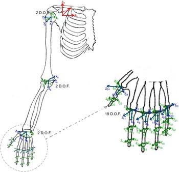
The derived kinematic model is verified for human upper limb extremities considering only revolute joints. The human upper limb extremity is designed with minimum possible inertia by keeping the motor axis minimum. The glenohumeral joint at shoulder allows the arm movements in three axes viz flexion–extension, abduction–adduction, medial rotation (internal rotation) and lateral rotation (external rotation), and circumduction [55]. Because, medial and lateral rotation of upper arm is not observed in most of the activities [Reference Namdari, Yagnik, Ebaugh, Nagda, Ramsey, Williams and Mehta56], rotational motion about the upper arm axis is neglected in this paper. For remaining motions, two motors are considered sufficient to generate the motion of spherical joint at shoulder. The first motor M1 and motor M2 are used for abduction–adduction and flexion–extension of the humerus (upper arm). The elbow joint (a hinge joint) generates the flexion–extension of the forearm, whereas muscles operate the ulna and radius bones to impart internal and external rotation of arm. These two motions at elbow joints are proposed to be created by considering two different motors M3 and M4 at the elbow joint. Motor M3 is used to rotate the forearm, followed by the flexion–extension motion by motor M4 mounted on motor M3. The wrist joint is supposed to have three-DOFs for generating flexion–extension, radioulnar deviation, and rotation [Reference Palmer, Werner, Murphy and Glisson57]. Because, wrist rotation is negligible [Reference Safaee-Rad, Shwedyk, Quanbury and Cooper58], this movement is not studied in this paper and hence, only two motors are considered at wrist joint. The carpus bones at the wrist joint produce two motions flexion–extension and radial–ulnar deviation of the wrist joint, which are proposed to be imparted by motors M5 and M6, respectively. Any motion created by metacarpal bones is neglected in the palm, and a rigid link is considered for the palm. The four fingers are considered to have four DOFs each, and the thumb is considered to have three DOFs resulting in 25 DOFs for the human upper limb. The fingers and thumb can be considered at specified locations on the palm as per literature available. Metacarpophalangeal (mcp) joint is responsible for abduction–adduction and flexion–extension motion of proximal phalanges and is represented by motors M7 and M8. Motors M9 and M10 are proposed for proximal interphalangeal (pip) and distal interphalangeal (dip) joints at fingers for flexion–extension of middle and distal phalanges of fingers. The home position of all joints for the upper limb extremity is considered with minimum energy and pointing towards the ground. The kinematic model of the proposed human upper limb extremity is shown in Fig. 3, represented by the composite matrix given in Eq. (19).
Kinematic model for human upper limb.

The human upper limb uses different combinations of joint rotations, for which the axes and sequence of rotations are determined by right-hand rule and Eulerian angle system I, respectively.
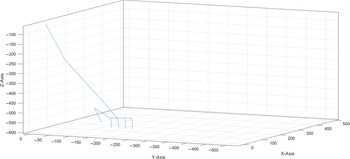
Eq. (19) represents the composite matrix (considering Denavit–Hartenberg parameters for Fig. 3) obtained by multiplying the individual composite matrices for the joints, that is, shoulder joint, elbow joint, wrist joint and hand. Figure 4 shows the human upper limb positions for the composite matrix developed in Eq. (19).
 \begin{align}\begin{array}{l}C' = {\left( {{R_{x,\frac{\pi }{2}}} \times {T_{{d_1},{\theta _1}}} \times {R_{z, - \frac{\pi }{2}}} \times {R_{x,\frac{\pi }{2}}} \times {T_{z,{\theta _1}}}} \right)_{{\rm{shoulder}}}} \times {T_{x,{L_1}}} \times {\left( {{T_{z,{\theta _3}}} \times {R_{z, - \frac{\pi }{2}}} \times {R_{x, - \frac{\pi }{2}}} \times {T_{z,{\theta _4}}}} \right)_{{\rm{elbow}}}} \times {T_{z,{L_2}}}\\[5pt] \times {\left( {{R_{x, - \frac{\pi }{2}}} \times {R_{z, - \frac{\pi }{2}}} \times {R_{x,\frac{\pi }{2}}} \times {T_{z,{\theta _5}}} \times {R_{x,\frac{\pi }{2}}} \times {T_{z,{\theta _6}}}} \right)_{{\rm{wrist}}}} \times {T_{x,{L_{{\rm{palm}}}}}}\\[5pt] \times {\left( \begin{array}{l}{\left( {{T_{z,{\theta _7}}} \times {R_{x, - \frac{\pi }{2}}} \times {T_{z,{\theta _8}}}} \right)_{{\rm{mcp}}\_m}} \times {T_{x,{L_{f1\_m}}}} \times {\left( {{T_{z,{\theta _9}}}} \right)_{{\rm{pip}}\_m}} \times {T_{x,{L_{f2\_m}}}}\\[8pt] \times {\left( {{T_{z,{\theta _{10}}}}} \right)_{{\rm{dip}}\_m}} \times {T_{x,{L_{f3\_m}}}} + {\left( {{R_{x, - \frac{\pi }{2}}} \times {T_{z,20}} \times {R_{x,\frac{\pi }{2}}} \times {T_{z,{\theta _{11}}}} \times {R_{x, - \frac{\pi }{2}}} \times {T_{z,{\theta _{12}}}}} \right)_{{\rm{mcp}}\_i}} \times {T_{x,{L_{f1\_i}}}} \times {\left( {{T_{z,{\theta _{13}}}}} \right)_{{\rm{pip}}\_i}} \times {T_{x,{L_{f2\_i}}}}\\[8pt] \times {\left( {{T_{z,{\theta _{14}}}}} \right)_{{\rm{dip}}\_i}} \times {T_{x,{L_{f3\_i}}}} + {\left( {{R_{x, - \frac{\pi }{2}}} \times {T_{z, - 20}} \times {R_{x,\frac{\pi }{2}}} \times {T_{z,{\theta _{15}}}} \times {R_{x, - \frac{\pi }{2}}} \times {T_{z,{\theta _{16}}}}} \right)_{{\rm{mcp}}\_r}} \times {T_{x,{L_{f1\_r}}}} \times {\left( {{T_{z,{\theta _{17}}}}} \right)_{{\rm{pip}}\_r}} \times {T_{x,{L_{f2\_r}}}}\\[8pt] \times {\left( {{T_{z,{\theta _{18}}}}} \right)_{{\rm{dip}}\_r}} \times {T_{x,{L_{f3\_r}}}} + {\left( {{R_{x, - \frac{\pi }{2}}} \times {T_{z, - 40}} \times {R_{x,\frac{\pi }{2}}} \times {T_{z,{\theta _{19}}}} \times {R_{x, - \frac{\pi }{2}}} \times {T_{z,{\theta _{20}}}}} \right)_{{\rm{mcp}}\_l}} \times {T_{x,{L_{f1\_l}}}} \times {\left( {{T_{z,{\theta _{21}}}}} \right)_{{\rm{pip}}\_l}} \times {T_{x,{L_{f2\_l}}}}\\[8pt] \times {\left( {{T_{z,{\theta _{22}}}}} \right)_{{\rm{dip}}\_l}} \times {T_{x,{L_{f3\_l}}}} + {\left( {{R_{x, - \frac{\pi }{2}}} \times {T_{z,40}} \times {T_{x, - 60}} \times {R_{x, - \frac{\pi }{4}}} \times {T_{z,{\theta _{23}}}} \times {R_{x, - \frac{\pi }{2}}} \times {T_{z,{\theta _{24}}}}} \right)_{{\rm{mcp}}\_t}} \times {T_{x,{L_{f1\_t}}}} \times {\left( {{T_{z,{\theta _{25}}}}} \right)_{ip\_t}} \times {T_{x,{L_{f2\_t}}}}\end{array} \right)_{{\rm{hand}}}},\end{array}\nonumber\\\end{align}
Human upper limb joint positions in 3D space for the developed composite matrix.

where R represents the rotation matrix for joints, and T represents the translation due to limb lengths. Z axis is identified as the axis of rotation of joints. Single-axis motors are considered for the analysis due to their simplicity resulting in a simplified joint analysis. Further,
 ${R_{x,\frac{\pi }{2}}}$
and
 ${R_{x, - \frac{\pi }{2}}}$
can be defined as rotation matrix for the frame change (changing z axis direction), which is obtained by rotating x axis by
 $\frac{\pi }{2}$
radians either in clockwise or counterclockwise directions, respectively and are presented in Eq. (20).
 ${R_{x,{\pi \over 2}}} = \left[ {\matrix{
1 & 0 & 0 & 0 \cr
0 & 0 & { - 1} & 0 \cr
0 & 1 & 0 & 0 \cr
0 & 0 & 0 & 1 \cr
} } \right],{\mkern 1mu} {R_{x, - {\pi \over 2}}} = {\rm{ }}\left[ {\matrix{
1 & 0 & 0 & 0 \cr
0 & 0 & 1 & 0 \cr
0 & { - 1} & 0 & 0 \cr
0 & 0 & 0 & 1 \cr } } \right]$
Similarly,
 ${R_{z,\frac{\pi }{2}}}$
and
 ${R_{z, - \frac{\pi }{2}}}$
represents frame rotation matrices (for changing x axis direction) by rotating z axis through
 $\frac{\pi }{2}$
radians either in clockwise or counterclockwise directions, respectively, and are presented in Eq. (21).
 $${R_{z,{\pi \over 2}}} = \left[ {\matrix{
0 & { - 1} & 0 & 0 \cr
1 & 0 & 0 & 0 \cr
0 & 0 & 1 & 0 \cr
0 & 0 & 0 & 1 \cr
} } \right],{\mkern 1mu} {R_{z, - {\pi \over 2}}} = \left[ {\matrix{
0 & 1 & 0 & 0 \cr
{ - 1} & 0 & 0 & 0 \cr
0 & 0 & 1 & 0 \cr
0 & 0 & 0 & 1 \cr } } \right]$$
 ${T_{x,L}}$
and
 ${T_{z,d}}$
are matrices for translation about the x axis (for limb length) and z axis (for motor shaft length d), respectively, given by
 $\matrix{
{{T_{x,L}} = \left[ {\matrix{
1 & 0 & 0 & L \cr
0 & 1 & 0 & 0 \cr
0 & 0 & 1 & 0 \cr
0 & 0 & 0 & 1 \cr
} } \right],{\mkern 1mu} {T_{z,d}} = \left[ {\matrix{
1 & 0 & 0 & 0 \cr
0 & 1 & 0 & 0 \cr
0 & 0 & 1 & d \cr
0 & 0 & 0 & 1 \cr
} } \right],} \hfill \cr } $
Mathematical expression, Eq. (23) given by [Reference Carpinella, Jonsdottir and Ferrarin29, Reference Zhang and Chaffin30], a modification of expression by [Reference Boston, Rudy, Mercer and Kubinski27], is used for angular displacement of joints, which is claimed to be more approximate and to exact behaviour of angular rotation of human subject. To reduce the complexity in computation, the relation between different joints is taken into account and left for further study.
 \begin{align}\theta \left( t \right) = {C_1} + {C_2}\tanh \left( {\frac{{t - {C_3}T}}{{{C_4}T}}} \right),\end{align}
where
 \begin{align}{C_1} = \frac{{\theta \left( 0 \right) + \theta \left( T \right)}}{2}\end{align}
and
 \begin{align}{C_2} = {{\theta \left( T \right) - \theta \left( 0 \right)} \over {\tanh \left( {{{1 - {C_3}} \over {{C_4}}}} \right) + \tanh \left( {{{{C_3}} \over {{C_4}}}} \right)}} \approx {{\theta \left( T \right) - \theta \left( 0 \right)} \over 2},\end{align}
where C 1 is the absolute mean position of angular displacement, which defines the constant offset influencing the absolute value of angles, C 2 is approximately the midpoint of the span of the profile which characterises the total angular displacement, C 3 determines the portion of time to reach the peak velocity, and C 4 determines the portion of total movement time used for the primary displacement.
The classical expression for the angular velocity is obtained as the time derivative of the expression [Reference Medved23] and is given as
 \begin{align}\omega \left( t \right) = \frac{{d\theta \left( t \right)}}{{dt}} = \frac{{{C_2}}}{{{C_4}T}}\sec {h^2}\left( {\frac{{t - {C_3}T}}{{{C_4}T}}} \right).\end{align}
3.1 Calculation of constants C3 and C4
Using initial and final joint movement parameters (boundary conditions), that is, angular velocities
 $\omega \left( 0 \right) = \omega \left( T \right) = 0,$
we get
 ${C_3} \le 1/2$
. C
3 value essentially quantifies the degree of symmetry in the profiles, particularly in the velocity domain—the velocity profile is left-skew if C
3 is less than 0.5 and right-skew if greater than 0.5. Based on the definition, C
3 is selected relatively equal to 0.5, assuming motion to be without dwell period and acceleration and retardation of joint movements to be the same. In addition, C
4 can be selected such that
 $\sec {h^2}\left( {\frac{{0.5}}{{{C_4}}}} \right) = 0$
. Now, C
4 can be varied in the range [0, C
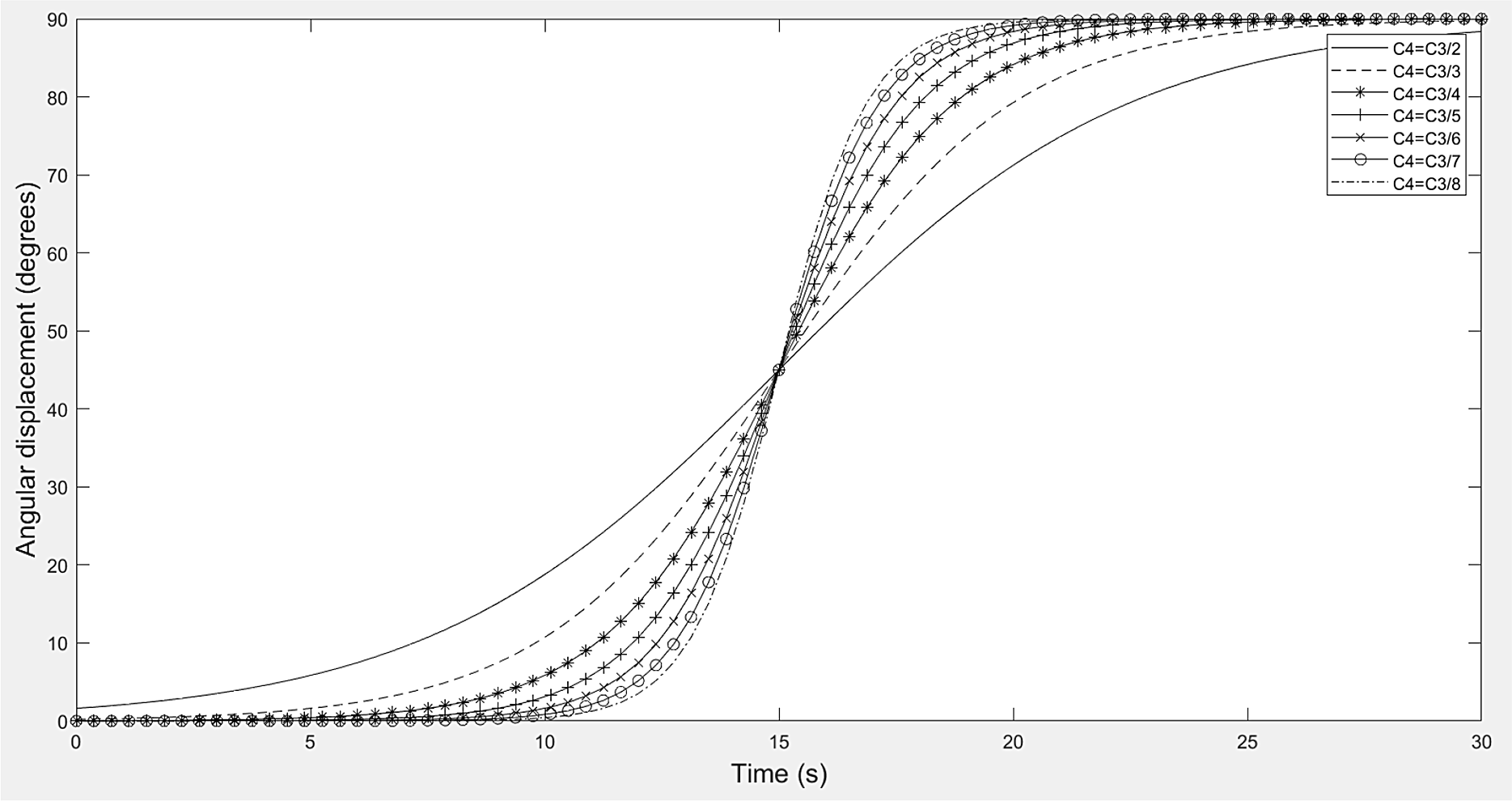
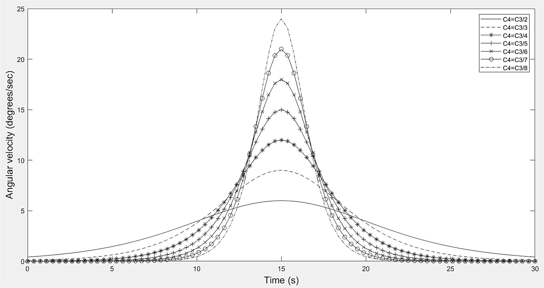
3/2]. The angular displacement profile (Fig. 5) and angular velocity profile (Fig. 6) get smoother with an increasing value of C
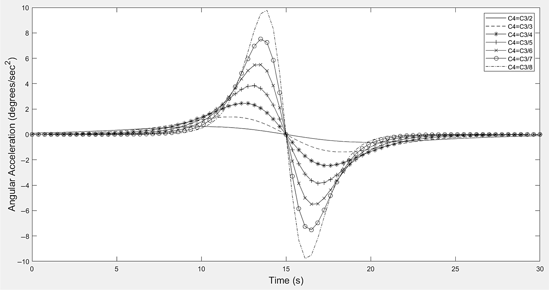
4. An increase in starting and stopping velocity and acceleration is observed for higher values of C
3 and an increase in peak velocity and acceleration values for less value of C
3 (observed in Figs. 6 and 7). To keep the entire profiles smooth for angular displacement, velocity and acceleration, C
4 is selected with a value equal to one-fourth of the rise time to reach peak velocity (C
3), that is, C
4 = C
3/2.
Angular displacement profile w.r.t. C4.

Varying angular velocity profile w.r.t. C4.

Varying angular acceleration profile w.r.t. C4.

Angular acceleration is obtained as the double-time derivative of expression for angular displacement [Reference Medved23] and is given as
 \begin{align}\alpha (t) = \frac{{{d^2}\theta \left( t \right)}}{{d{t^2}}} = \frac{{ - 2{C_2}}}{{{{\left( {{C_4}T} \right)}^2}}}\tanh \left( {\frac{{t - {C_3}T}}{{{C_4}T}}} \right)\sec {h^2}\left( {\frac{{t - {C_3}T}}{{{C_4}T}}} \right) = \frac{{ - 2\omega \left( t \right)}}{{{C_4}T}}\tanh \left( {\frac{{t - {C_3}T}}{{{C_4}T}}} \right).\end{align}
4. Analysis of Kinematic Parameters for the Human Upper Limb Model
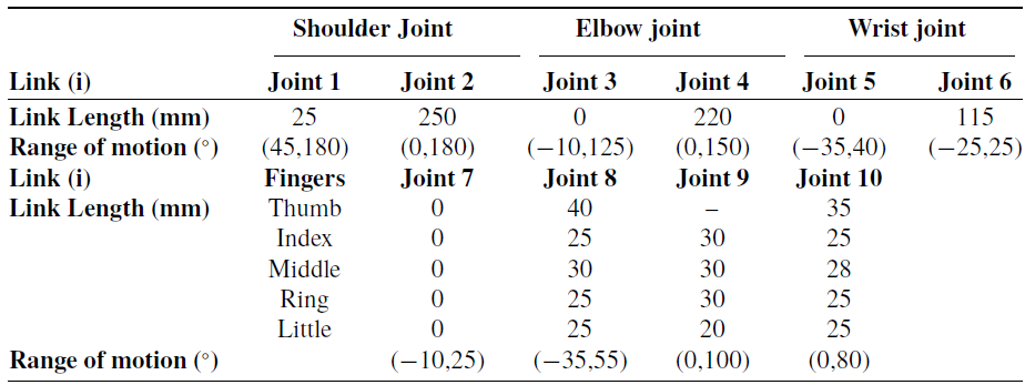
Based on the various literature present for the human limb length ratios [Reference Parida, Biswal and Thatoi59–Reference Peña-Pitarch, Falguera and Yang61], Table I (link lengths and joint angles for 1.80 m height of an average man) are used in the expressions for kinematic analysis of the human upper limb (Fig. 3). Axes are decided for generation of required motion at the joints to choose D-H parameters (appendix) and developed composite matrix (Eq. 19) for required for kinematic analysis. A MATLAB program was developed for the study of kinematic parameters. The planes are rotated in the required sequence as in the D–H Table (appendix) to achieve the desired axis at the joints (Fig. 3). Motors (Mi) are considered for analysis at i th joints producing θ i rotation. The time of flight for motor for all joints is considered to be 30 s. For better understanding, the joint angle movements for all fingers (including thumb) are considered to be the same, reducing the joint movement counts from 25 to 10.
Link parameters considered for analysis.

Joint velocity behaviour (Eq. 6) is a resultant effect of position gradients
 $\left( {\frac{{\partial {P_i}}}{{\partial {\theta _i}}}} \right)$
and angular velocity (
 ${\dot \theta _i}$
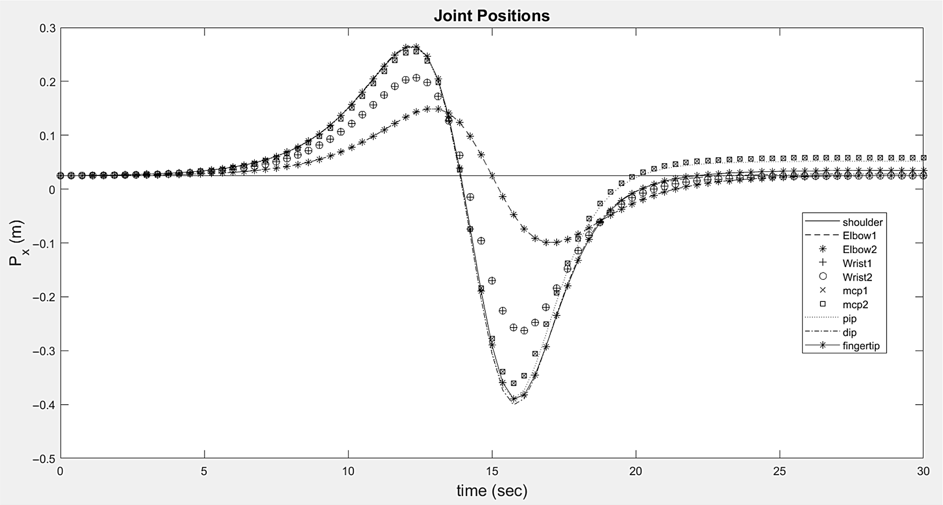
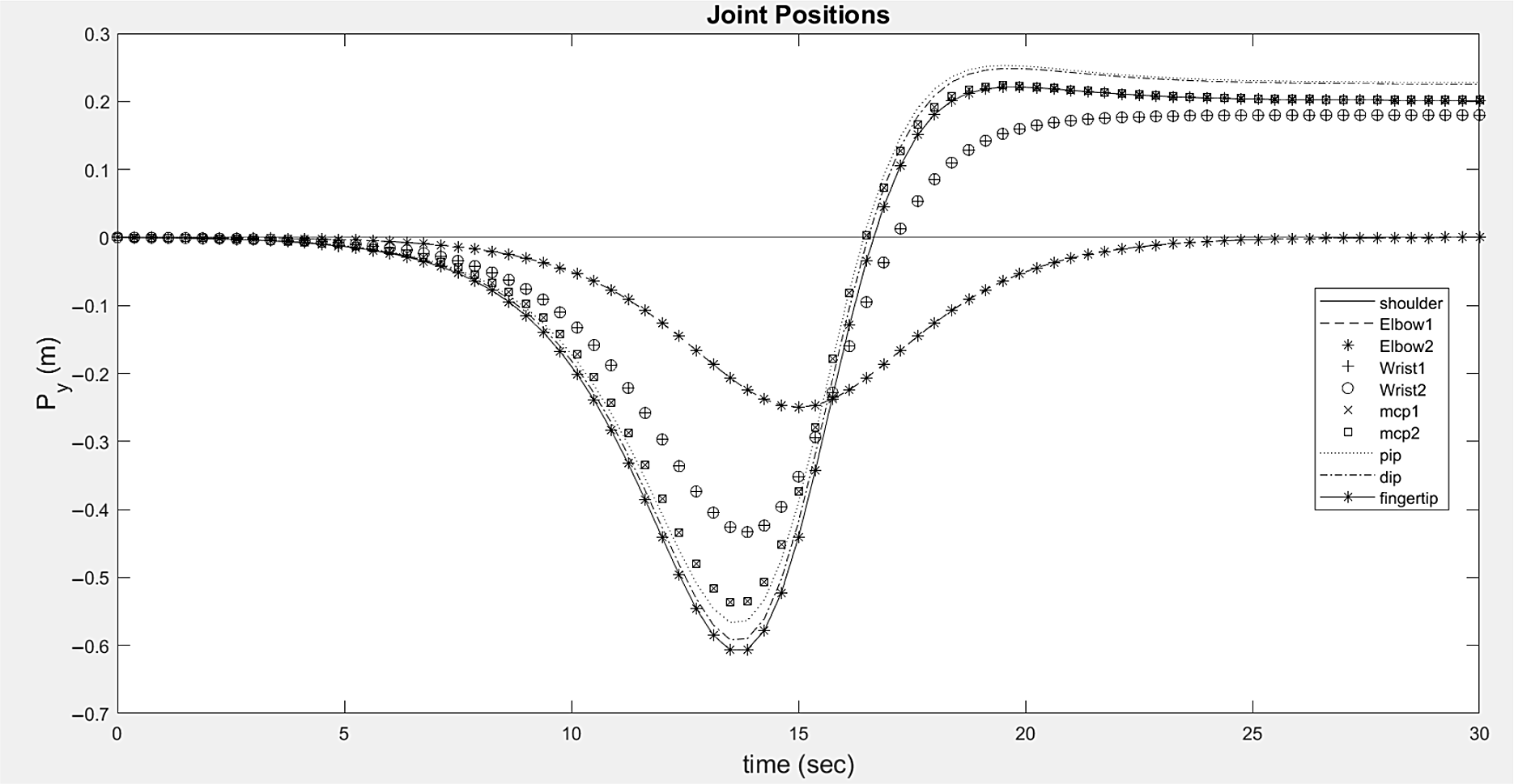
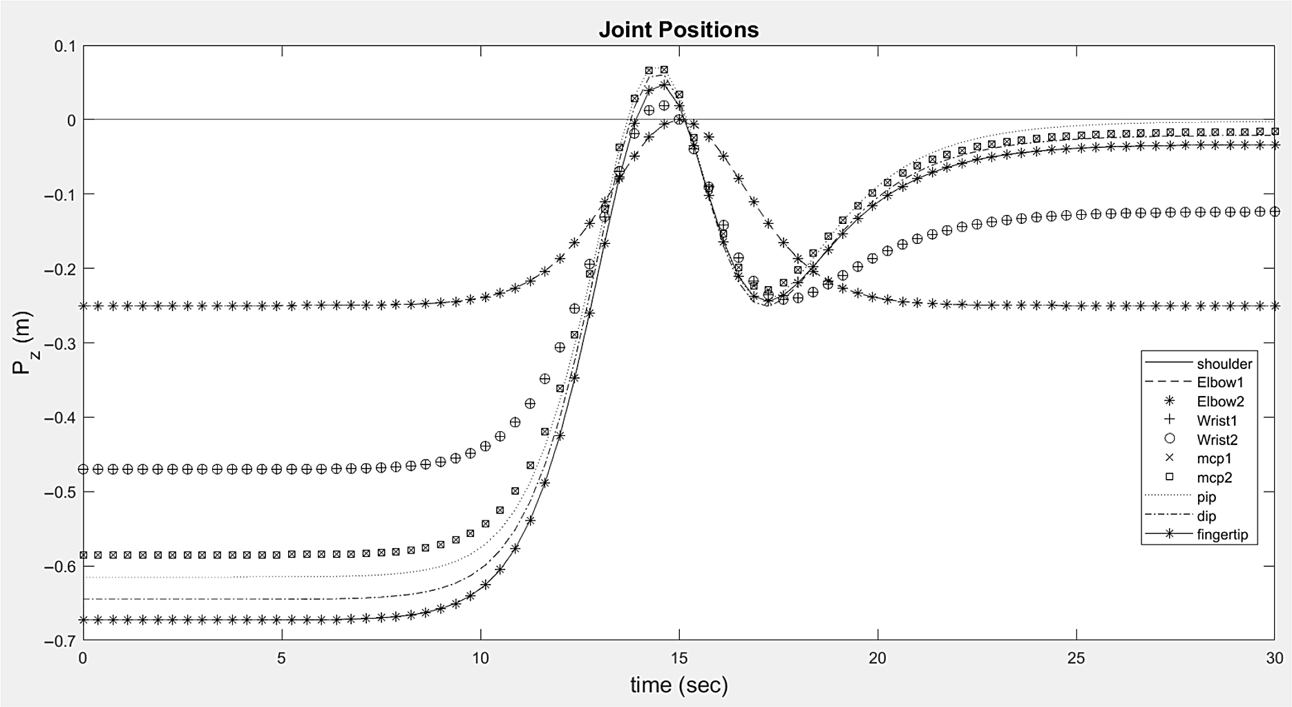
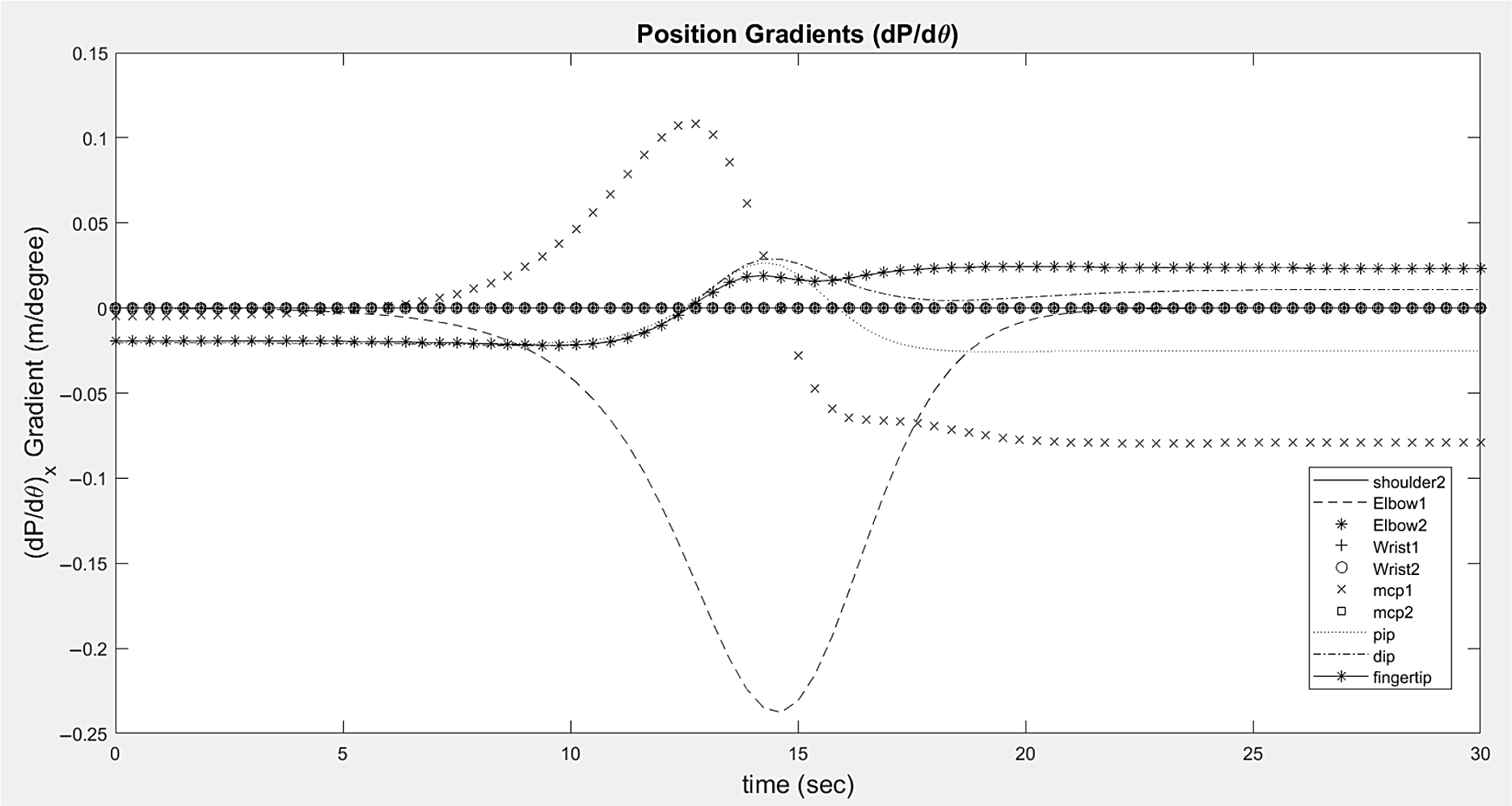
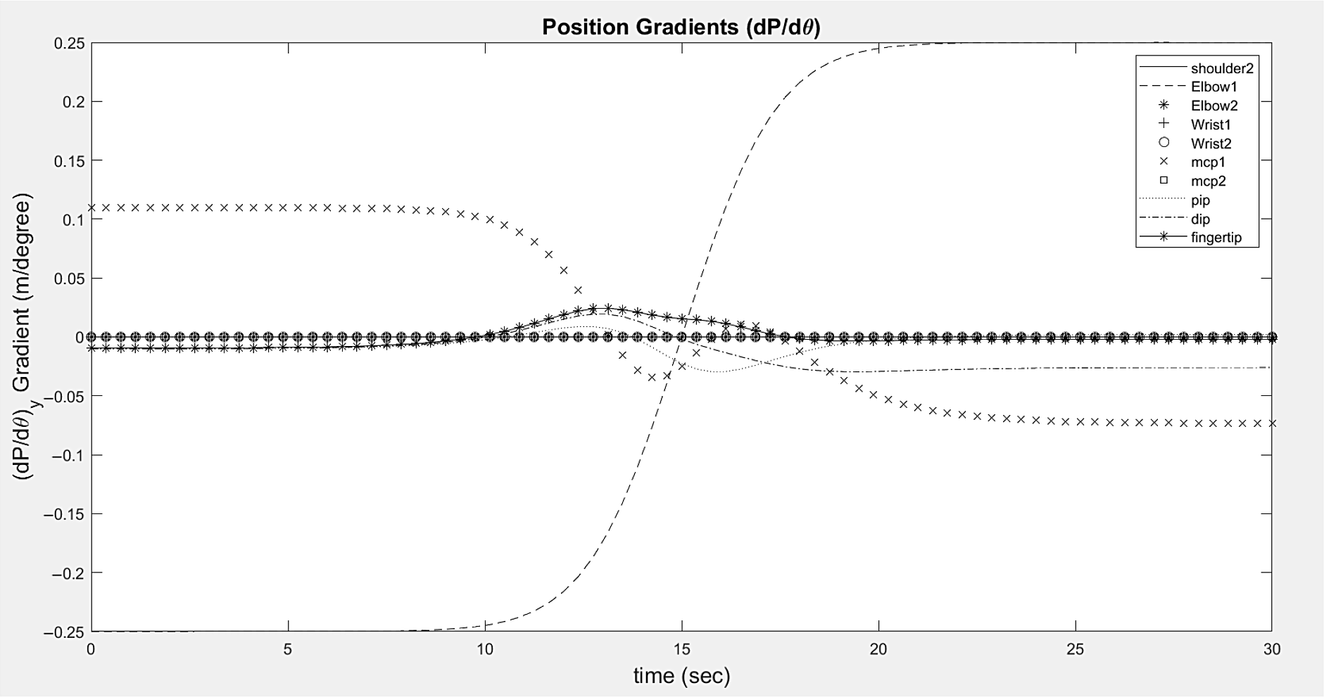
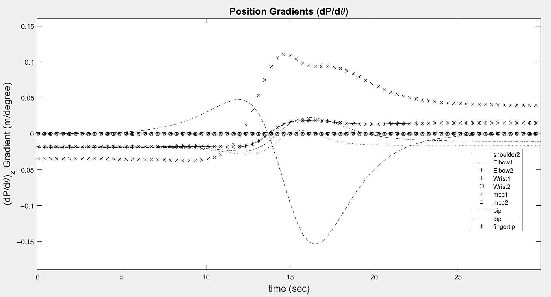
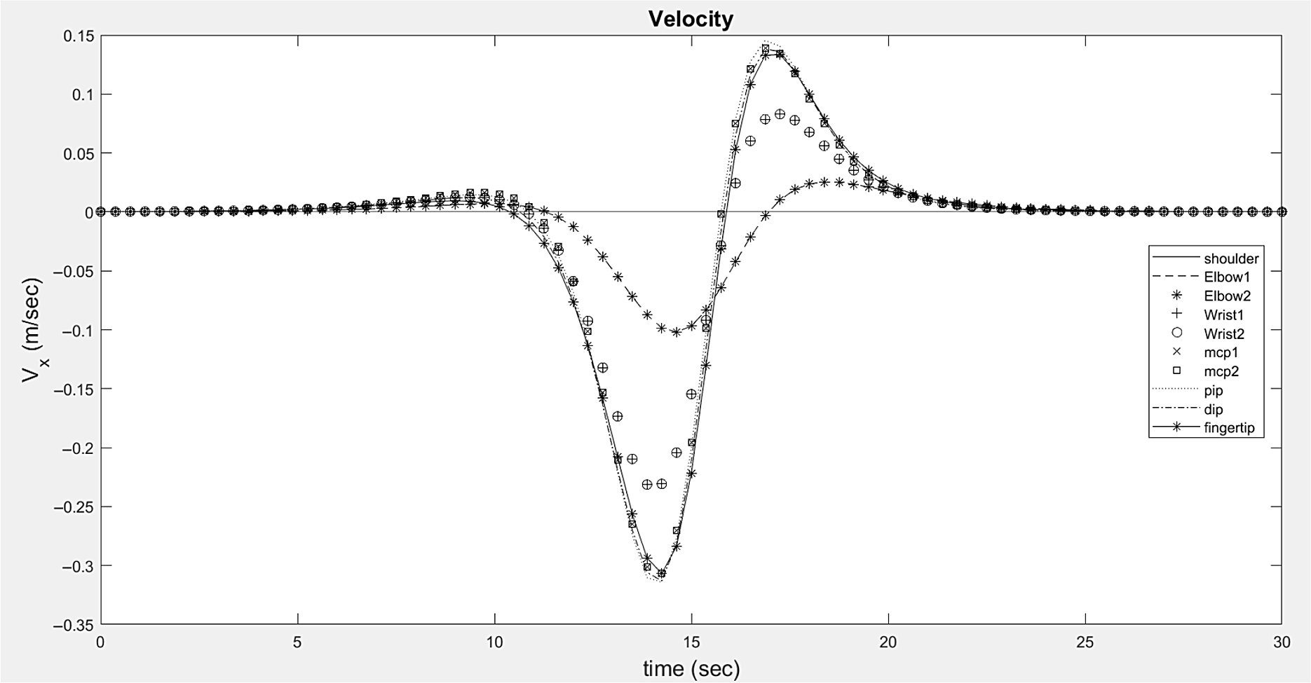
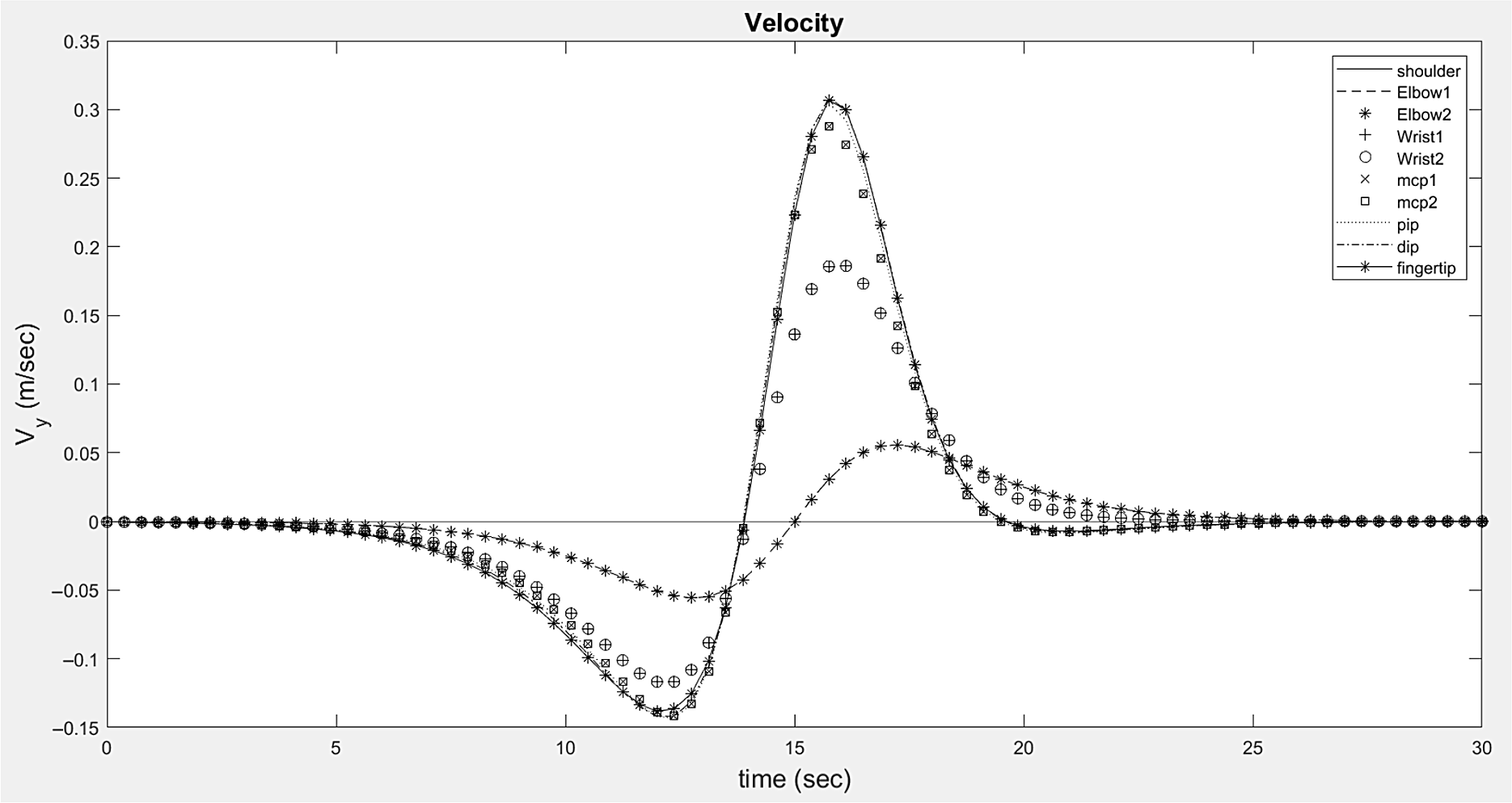
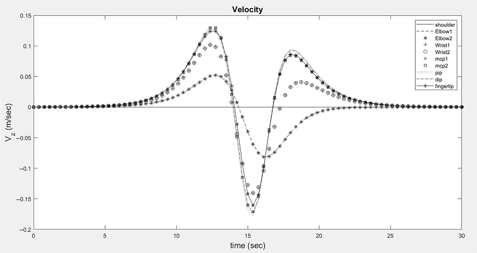
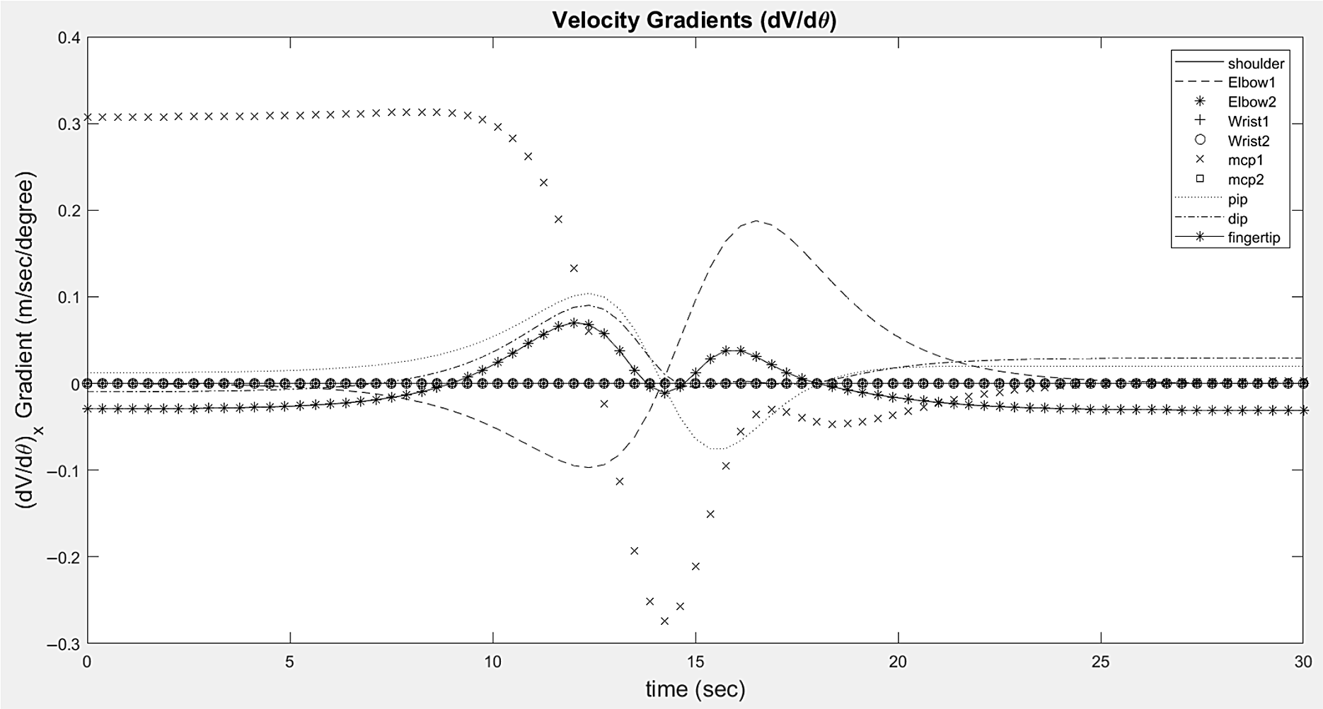
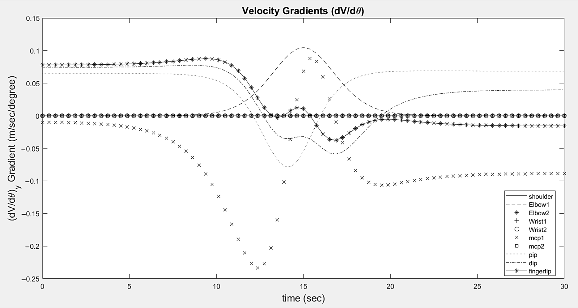
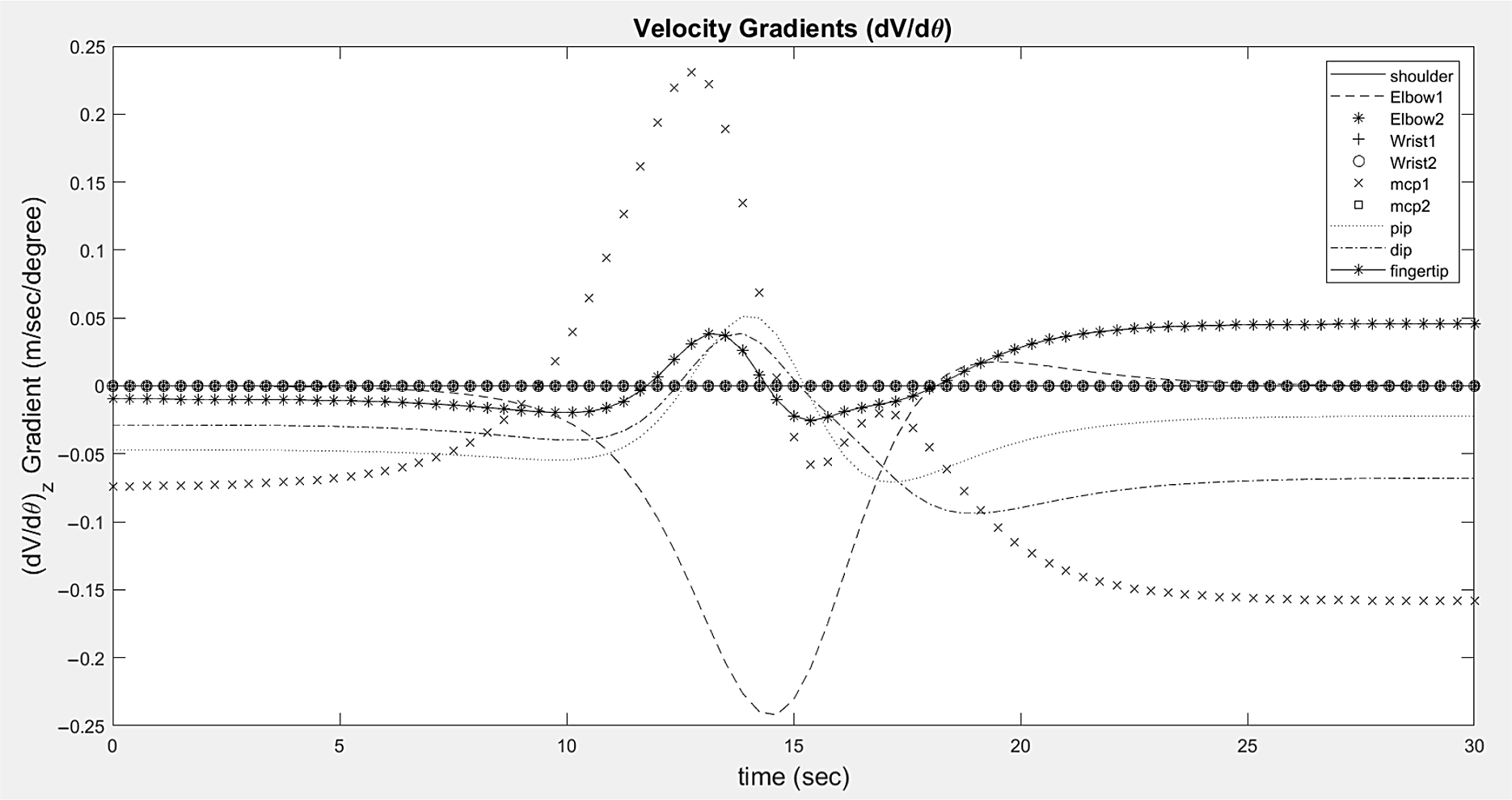
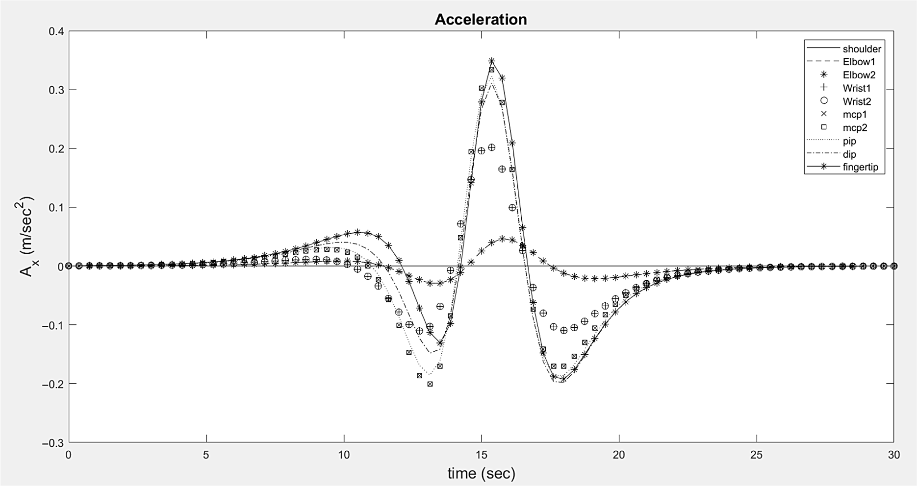
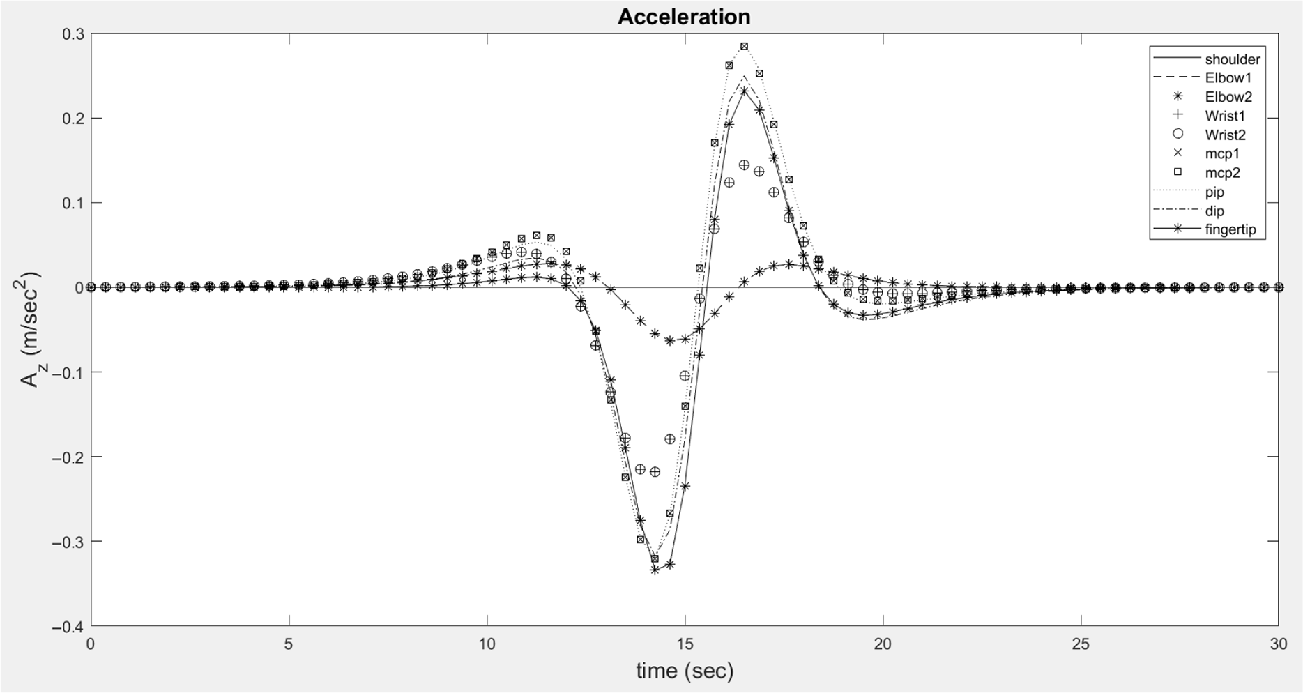
). Therefore, behaviour of angular velocity in Fig. 6 and potential gradients in Figs. 11–13 is studied to determine the behaviour of joint velocities (Figs. 14–16). In addition, joint acceleration (Eq. 14) also depends on the position gradients to calculate different terms such as centripetal acceleration and Coriolis acceleration and velocity gradient to determine the tangential component of acceleration. Figures 17–19 determine the gradient behaviour of velocity components (V
x
, V
y
and V
z
). Figures 20–22 show the behaviour of resultant accelerations at different joints. The gradients and velocity, and accelerations at the joints increase with increasing distance of the joints from the reference frame (shoulder complex, see Fig. 3). Since the first motor M1 is fixed on the frame, the components of linear velocities and accelerations, that is, position gradients and velocity gradients, will be zero for motor M2 resulting in zero effective joint velocities and joint accelerations.
Joint position (Px) variation for all joints.

Joint position (Py) variation for all joints.

Joint position (Pz) variation for all joints.

Position gradient (dP/dθ)x variation for all joints.

Position gradient (dP/dθ)y variation for all joints.

Position gradient (dP/dθ)z variation for all joints.

Variation of linear velocity (Vx) for all joints.

Variation of linear velocity (Vy) for all joints.

Variation of linear velocity (Vz) for all joints.

Variation of velocity gradient (dV/dθ)x for all joints.

Variation of velocity gradient (dV/dθ)y for all joints.

Variation of velocity gradient (dV/dθ)z for all joints.

Variation of linear acceleration (Ax) for all joints.

Variation of linear acceleration (Ay) for all joints.

Variation of linear acceleration (Az) for all joints.

All the joints are rotated simultaneously within the range of motion decided in Table I for the same time of rotation (i.e., 30 s). Figure 8 shows the positions of the different joints. In addition, the shoulder joint motor (M2) fixed on the joint motor (M1), neglecting the motor shaft length. The motor M2 is under the influence of pure rotation of motor (M2). Therefore, the position change is not observed for shoulder joint motor (M1) in all x, y and z directions. Similarly, the motor shaft length is neglected for elbow, wrist and mcp joints, and hence, the graph for this set of joints coincides with all the profiles (Figs. 8–22).
The position curves are obtained as a combined effect of joint rotations, and the sinusoidal curve is obtained with maximum distance nearly at the midpoint of the time of flight. The starting and final joint positions are achieved for initial and final joint rotations and are shown in Figs. 8–10 at time [0, 30] seconds within the joint angles [0, θ max]. However, the maximum reach of the human upper limb in the space can be obtained by rotating only the shoulder joint (M1 and M2) and keeping the remaining joints at initial conditions, that is, zero angular displacements at each joint.
The position gradients are studied in Figs. 11–13 for simultaneous rotation of each joint within the complete range of rotation (Table I). The effect of previous position gradients is summed up (Eq. 5) and increases with the increase in the joint distance from the reference frame. The behaviour of position gradients at each joint is studied to determine its contribution in determining the profile of joint velocities. A sinusoidal curve is obtained for position gradients.
All joints are rotated sequentially for performing any activity, for example, elbow joint rotation is followed by shoulder and wrist rotations. However, joint velocity behaviour is carried out for simultaneously rotating all joints of the human upper limb. The joint velocities are obtained by adding up all the previous joint velocities with the product of position gradient and joint angular velocities. The profile for all the joint velocities (Figs. 14–16) obtained are similar to that for position gradients in all x, y and z coordinates. The joint velocity for the shoulder joint is obtained to be zero for the complete range of motion as the shoulder (M1 and M2) is under pure rotation, and both joints are considered at the frame. The pair of motors at the shoulder joint (M1 and M2), elbow (M3 and M4), wrist joint (M5 and M6) and finger mcp joint (M7 and M8) have the same velocities as these motors are mounted on the same joint with negligible displacement. Zero velocity is obtained at the start and stop of the joint rotation for all joints motors.
The behaviour of velocity gradient
 $\left(\frac{{\partial {}^{i - 1}{V_i}}}{{\partial {\theta _i}}} = \left( {{}^0{C_{i - 1}} \times \frac{{{\partial ^2}{}^{i - 1}{R_i}}}{{\partial {\theta ^2}_i}} \times \dot{\theta}_i + {W_{i - 1}} \times \frac{{\partial {}^{i - 1}{R_i}}}{{\partial {\theta _i}}}} \right)\right)$
is studied as it introduces two terms in the expressions for linear acceleration (Eq. 14), that is, tangential acceleration (ω 2
r) and Coriolis component of acceleration. Therefore, the study of the effect of velocity gradients on linear acceleration is important. The profile for velocity gradients has sinusoidal behaviour with increased frequency. Some deviation from sinusoidal behaviour is obtained because of the combined effect of velocity gradients at previous joints. The velocity gradient for the shoulder joint and second elbow joint is negligible because these joints are under pure angular rotations. The velocity gradient increases with increasing distance from the frame. The velocity gradients in Figs. 17–19 have some initial and final values.
Linear acceleration at joints (Eq. 14) has four terms, that is, tangential component, Coriolis component, centripetal component of acceleration and effective linear acceleration up to previous joints. The tangential component (ω 2 r) and Coriolis component of accelerations are perpendicular to the link in the rotation direction. This Coriolis component can be added up centripetal component of acceleration (αr) to get an effective centripetal component of acceleration (2ω i−1 ω i ) deviated from the centre of the joint. The linear acceleration has a combined effect of joint angular velocities, position gradients, velocity gradients, and joint angular acceleration, adding to the effective linear acceleration up to the previous joint. Adding all the effects, the profile for the linear acceleration becomes smooth with sinusoidal behaviour having zero acceleration at start and stop of joint rotations.
Linear acceleration at the shoulder joint (M1 and M2) is zero as it is subjected to pure rotation with negligible length. The acceleration is observed to be zero at the start and stop for all joints. The maximum acceleration for remaining joints increases with an increase in distance from the fixed frame and is concentrated near the midpoint of time of rotation due to the low value of constant C 4 (Figs. 20–22).
5. Conclusion
Most of the researchers have worked independently for human upper limb up to wrist and hand. In addition, sensors are used for limited analysis of the human upper limb behaviour for task-based operations. Because, the rotational of previous joints has a significant role in determining the movements of joints, this research is aimed to develop a matrix approach based mathematical model to find a relation between two consecutive links for kinematic analysis of an n-link three-dimensional manipulator. Different terms involved in the analysis of velocities and accelerations are considered by justifying with derived relations. This approach is found suitable for programming in any language. The human upper limb with 25-DOF is reduced to 10-DOF, assuming fingers (including) movements to be symmetrical, is considered for kinematic analysis using this approach. Link velocity analysis is carried out by considering same time for entire range of joint rotation. Position and position gradient terms are used with velocity gradients and angular velocities and angular acceleration to determine its relation with the previous link. The effect of the constituent terms is analysed to determine the final velocity and accelerations. The maximum velocity and acceleration obtained during acceleration and retardation of the motion are obtained near the midpoint of rotation, changing behaviour at the midpoint. The same velocities are obtained for the pair of motors at the shoulder joint, elbow joint, wrist joint and finger mcp joint as these pair of motors are considered to be in the same single frame. However, the motor shaft length may be considered for the extremities in the matrix in the composite matrix and program to identify the effect.
The velocities and accelerations for the shoulder joint motors (M1 and M2) are zero because these motors are under pure rotation with neglected motor shaft lengths. For other pairs of motors at the elbow, wrist, and finger mcp joints, the effective velocities and accelerations are the same. Almost all motors from the elbow joint to finger joints experience sinusoidal behaviour for effective joint velocities and joint accelerations.
This upper limb model can further be used to analyse different daily activities by upper limb (such as eating, writing and gripping) or sports activities (such as bowling, javelin throw) by considering sequential joint movements. The kinematic parameters for the electric motors can also be studied in future for determining the real kinematic parameters for an extremity and hence, proposal of suitable control algorithms. Matrix approach used in this kinematic model makes it suitable for extending it to determine the kinematic parameters for human lower limbs. The kinematic parameters determined by the kinematic analysis are important for determining joint torques (inverse dynamics) using energy method (considering kinetic and potential energies), which is again a vast topic for discussion. This work can be extended for determining the optimum kinematic parameters for minimum joint torques (energy) for a task-based operation and avoiding singularities.
Supplementary material
To view supplementary material for this article, please visit https://doi.org/10.1017/S0263574721001387
Appendix D–H Table