1 Introduction
High-frequency electron plasma waves are often found in nature (Bonnell et al.
Reference Bonnell, Kintner, Wahlund and Holtet1997; Burinskaya, Rauch & Mogilevskii Reference Burinskaya, Rauch and Mogilevskii2004; LaBelle, Cairns & Kletzing Reference LaBelle, Cairns and Kletzing2010; Briand Reference Briand2015; Píša et al.
Reference Píša, Hospodarsky, Kurth, Santolík, Souček, Gurnett, Masters and Hill2015) and they are easily excited also in a laboratory by antennae immersed in the plasma, or by electron beams (Michelsen et al.
Reference Michelsen, Pécseli, Rasmussen and Sato1977; Vyacheslavov et al.
Reference Vyacheslavov, Burmasov, Kandaurov, Kruglyakov, Meshkov and Sanin1995; McFarland & Wong Reference McFarland and Wong1997). These waves are also excited to significant amplitudes in ionospheric heating experiments (Kuo Reference Kuo2015a
). Many of the related analytical studies addressed homogeneous and isotropic conditions which can serve as a reference case for illustrating some general nonlinear wave phenomena. For conditions in nature, in the Earth’s ionosphere and magnetosphere in particular, we often find that even weak magnetic fields will be important, and in the present study we take the resulting anisotropy into account. The basic equations are changed significantly. In terms of the wave dispersion relation
 $\unicode[STIX]{x1D714}(\boldsymbol{k})$
, a mathematically interesting new feature (as compared to unmagnetized Langmuir waves) is that for wave propagation along the magnetic field
 $\boldsymbol{B}_{0}\Vert \widehat{\boldsymbol{z}}$
the two wave dispersion components
 $\unicode[STIX]{x2202}^{2}\unicode[STIX]{x1D714}(\boldsymbol{k})/\unicode[STIX]{x2202}^{2}k_{\bot }$
and
 $\unicode[STIX]{x2202}^{2}\unicode[STIX]{x1D714}(\boldsymbol{k})/\unicode[STIX]{x2202}^{2}k_{\Vert }$
have the same sign, while the two signs can, for small wavenumbers, be opposite for wave propagation
 $\bot \boldsymbol{B}_{0}$
.
The standard reference model for weakly nonlinear electron plasma waves assumes the dominant nonlinearity to be a modification of the local plasma density (i.e. the index of refraction) (Zakharov Reference Zakharov1972; Kono & Škorić Reference Kono and Škorić2010). Kinetic effects such as linear Landau damping and nonlinear particle trapping are ignored from the outset in the description of the high-frequency electron waves, and we argue that these effects will become negligible when the characteristic wavelengths
 $\unicode[STIX]{x1D706}$
are sufficiently long. (For many laboratory conditions it might become difficult to fulfil this condition due to the finite size of the apparatus.) Nonlinearities associated with, for instance, the adiabatic electron motion will be of the order of
 $(\unicode[STIX]{x1D706}_{De}/\unicode[STIX]{x1D706})^{2}$
and can be ignored (Dysthe & Pécseli Reference Dysthe and Pécseli1977), assuming again that the Debye length
 $\unicode[STIX]{x1D706}_{De}$
is much smaller than any relevant wavelength. The origin of the dominating nonlinear term here is in the space–time varying density of the electron continuity equation.
The present study considers the space–time evolution of high-frequency electrostatic waves in weakly magnetized plasmas as considered also in other works (Petviashvili Reference Petviashvili1975; Porkolab & Goldman Reference Porkolab and Goldman1976; Krasnosel’skikh & Sotnikov Reference Krasnosel’skikh and Sotnikov1977; Shukla Reference Shukla1977; Freund & Papadopoulos Reference Freund and Papadopoulos1980; Weatherall, Goldman & Nicholson Reference Weatherall, Goldman and Nicholson1981; Ovenden, Statham & Haar Reference Ovenden, Statham and Haar1983; Kasymov et al.
Reference Kasymov, Näslund, Starodub and Stenflo1985; Pécseli Reference Pécseli1985; Liu & Tripathi Reference Liu and Tripathi1986; Shukla & Farid Reference Shukla and Farid1999). The new feature will here be an account for a systematic transition from a single mode to multi-wave modes, with a continuous broad wave spectrum being a limiting case. The assumption of weak magnetic fields will be essential for the dispersion of the waves, where it is known that when
 $\unicode[STIX]{x1D714}_{\text{ce}}>\unicode[STIX]{x1D714}_{\text{pe}}/\sqrt{3}$
, kinetic effects give rise to a change in the curvature of the dispersion relation at small wavenumbers (Kaufman & Stenflo Reference Kaufman and Stenflo1975; Dysthe et al.
Reference Dysthe, Mjølhus, Pécseli and Stenflo1984; Faria & Shukla Reference Faria and Shukla1999) as compared to the standard fluid result. Strong magnetic fields thus necessitate a kinetic rather than a fluid model for the wave dynamics, although some simplifications can be obtained also for the kinetic model so that it can be incorporated into fluid models (Dysthe et al.
Reference Dysthe, Mjølhus, Pécseli and Stenflo1984). The possibility of modulational instability of plane weakly nonlinear electron waves in weakly magnetized plasmas was studied elsewhere (Dysthe et al.
Reference Dysthe, Mjølhus, Pécseli and Stenflo1978; Pozzoli & Ryutov Reference Pozzoli and Ryutov1979), and the nonlinear frequency shifts in particular. The present analysis extends the previous results and includes also wave decay. The modulational instabilities usually have a small growth rate compared to decay instabilities, but they can be important nonetheless. A modulationally unstable wave field is likely to become strongly intermittent, i.e. to break up into localized regions of enhanced wave activity.
The aim of the present study is to analyse the stability of wide band electron wave spectra. A plane wave can, however, be seen as a limiting case of a narrow band spectrum and that case is analysed as well, in particular also because it is seemingly sparsely covered in the literature (Dysthe et al. Reference Dysthe, Mjølhus, Pécseli and Stenflo1978; Freund & Papadopoulos Reference Freund and Papadopoulos1980; Weatherall et al. Reference Weatherall, Goldman and Nicholson1981). For the given plasma parameters some of the results may appear counter-intuitive. This simple limiting analysis is extended by considering the stability of two and also four plane waves. For the general case of finite width spectra we give most attention to waves predominantly propagating in a directional interval centred along the magnetic field, since these are most easily excited by, say, field aligned electron beams. Other wave directions can be excited by distorted electron velocity distributions.
The present summary is a part of a work with a wider scope attempting a formulation of dynamic theory for spatially modulated wide band electron wave spectra. A framework for such a theory has been developed and supplementary material is available separately (Kono & Pécseli Reference Kono and Pécseli2017). The most obvious application of such a general theory will, however, concern the stability of a wide band spectrum and we found that this particular result can be obtained more easily, and these results are presented here. The ideas outlined in the present work and by Kono & Pécseli (Reference Kono and Pécseli2017) can be used also for other wave forms.
2 Basic equations for the nonlinear high-frequency wave field
As our basic equation for weakly nonlinear electron plasma waves in weakly magnetized plasmas we take (Krasnosel’skikh & Sotnikov Reference Krasnosel’skikh and Sotnikov1977; Dysthe et al. Reference Dysthe, Mjølhus, Pécseli and Stenflo1985)
 $$\begin{eqnarray}\unicode[STIX]{x1D6FB}^{2}\left(\frac{\unicode[STIX]{x2202}^{2}}{\unicode[STIX]{x2202}t^{2}}-\unicode[STIX]{x1D710}^{2}\unicode[STIX]{x1D6FB}^{2}+\unicode[STIX]{x1D714}_{\text{pe}}^{2}\right)\unicode[STIX]{x1D719}+\unicode[STIX]{x1D714}_{\text{ce}}^{2}\unicode[STIX]{x1D6FB}_{\bot }^{2}\unicode[STIX]{x1D719}=-\unicode[STIX]{x1D735}\boldsymbol{\cdot }\left(\unicode[STIX]{x1D714}_{\text{pe}}^{2}\frac{\overline{n}}{n_{0}}\unicode[STIX]{x1D735}\unicode[STIX]{x1D719}\right),\end{eqnarray}$$
where
 $\unicode[STIX]{x1D719}=\unicode[STIX]{x1D719}(\boldsymbol{r},t)$
is the electrostatic wave potential. Here and in the following, the electron plasma frequency is denoted
 $\unicode[STIX]{x1D714}_{\text{pe}}$
, the electron cyclotron frequency is
 $\unicode[STIX]{x1D714}_{\text{ce}}$
, a characteristic particle velocity is defined as
 $\unicode[STIX]{x1D710}\equiv \sqrt{3T_{e}/m}$
and
 $\unicode[STIX]{x1D6FB}_{\bot }^{2}=\unicode[STIX]{x2202}^{2}/\unicode[STIX]{x2202}x^{2}+\unicode[STIX]{x2202}^{2}/\unicode[STIX]{x2202}y^{2}$
, with the magnetic field being along the
 $z$
-axis. The physical potential is related to the amplitude (or envelope) potential by
 $(1/2)\unicode[STIX]{x1D719}(\boldsymbol{r},t)\text{e}^{-\text{i}\unicode[STIX]{x1D714}t}+\text{c.c.}$
, and it is assumed that the potential amplitude varies over a time scale much longer than the plasma period
 $2\unicode[STIX]{x03C0}/\unicode[STIX]{x1D714}_{\text{pe}}$
. The analysis of the high-frequency wave is thus based on a fluid model, which imposes some limitations even for weak magnetic fields, i.e. some wave decay possibilities will be lost (Brodin & Stenflo Reference Brodin and Stenflo2016).
The linear dispersion relation associated with (2.1) is readily found as
 $$\begin{eqnarray}\displaystyle \unicode[STIX]{x1D714}^{2}=\unicode[STIX]{x1D714}_{\text{pe}}^{2}+\unicode[STIX]{x1D710}^{2}k^{2}+\unicode[STIX]{x1D714}_{\text{ce}}^{2}\frac{k_{\bot }^{2}}{k^{2}}. & & \displaystyle\end{eqnarray}$$
The upper hybrid frequency is
 $\unicode[STIX]{x1D714}_{\text{uh}}\equiv \sqrt{\unicode[STIX]{x1D714}_{\text{pe}}^{2}+\unicode[STIX]{x1D714}_{\text{ce}}^{2}}$
. The waves are assumed to be electrostatic also in the weakly nonlinear limit considered here: for a linearized analysis this restriction is immaterial for wave propagation along magnetic field lines, but for off-angle propagation at some
 $\unicode[STIX]{x1D703}$
we have the restriction
 $(\unicode[STIX]{x1D714}/\unicode[STIX]{x1D714}_{\text{ce}})(\unicode[STIX]{x1D714}_{\text{pe}}/kc)^{2}\sin \unicode[STIX]{x1D703}$
 $\ll 1$
. For
 $\unicode[STIX]{x1D703}\neq 0$
the waves will have a fluctuating magnetic component for small wavenumbers (Dysthe et al.
Reference Dysthe, Mjølhus, Pécseli and Stenflo1978).
2.1 High-frequency waves
We now remove the rapidly varying, high-frequency part of the signal by the standard substitution
 $\unicode[STIX]{x1D719}\rightarrow \unicode[STIX]{x1D719}(\boldsymbol{r},t)\exp (-\text{i}\unicode[STIX]{x1D714}_{0}t)$
, with
 $\unicode[STIX]{x1D714}_{0}$
being the carrier wave frequency. When
 $|\unicode[STIX]{x2202}\unicode[STIX]{x1D719}/\unicode[STIX]{x2202}t|\ll |\unicode[STIX]{x1D714}_{0}\,\unicode[STIX]{x1D719}|$
we obtain
 $$\begin{eqnarray}\left(\text{i}\frac{\unicode[STIX]{x2202}}{\unicode[STIX]{x2202}t}+\frac{1}{2}\frac{\unicode[STIX]{x1D710}^{2}}{\unicode[STIX]{x1D714}_{\text{pe}}}\unicode[STIX]{x1D6FB}^{2}\right)\unicode[STIX]{x1D6FB}^{2}\unicode[STIX]{x1D719}-\frac{1}{2}\frac{\unicode[STIX]{x1D714}_{\text{ce}}^{2}}{\unicode[STIX]{x1D714}_{\text{pe}}}\unicode[STIX]{x1D6FB}_{\bot }^{2}\unicode[STIX]{x1D719}=\frac{1}{2}\unicode[STIX]{x1D714}_{\text{pe}}\unicode[STIX]{x1D735}\boldsymbol{\cdot }\left(\frac{\overline{n}}{n_{0}}\unicode[STIX]{x1D735}\unicode[STIX]{x1D719}\right).\end{eqnarray}$$
We explicitly use
 $\unicode[STIX]{x1D714}_{0}\approx \unicode[STIX]{x1D714}_{\text{uh}}\approx \unicode[STIX]{x1D714}_{\text{pe}}$
as appropriate for weakly magnetized plasmas (Krasnosel’skikh & Sotnikov Reference Krasnosel’skikh and Sotnikov1977), with
 $\unicode[STIX]{x1D714}_{\text{ce}}\ll \unicode[STIX]{x1D714}_{\text{pe}}$
. In this limit the nonlinear frequency shift (Kadomtsev & Karpman Reference Kadomtsev and Karpman1971) is due to a change in the local bulk plasma density induced by the wave nonlinearity. The model (2.3) is often used, but can be generalized to include the effect also of the low-frequency convection of the high-frequency wave field (Volokitin & Krafft Reference Volokitin and Krafft2005).
One consequence of the magnetic field is that the group velocity
 $\boldsymbol{u}_{g}$
is in general no longer parallel to the wave vector. This has implications for the filamentation instability, in particular.
2.2 Equations for the low-frequency density variations
We now relate the variations of the high-frequency potential to the slow variations in plasma density. The simplest relation relevant here assumes that ponderomotive forces associated with the spatial variation of the high-frequency wave field sets the electrons into slow bulk motions. The resulting charge imbalance gives rise to slowly varying electric fields that sets also the ion component into motion.
2.2.1 Average force relations
Averaging the electron momentum over the fast time scale
 $\unicode[STIX]{x1D714}_{\text{pe}}^{-1}$
we obtain an expression for the balance between the electrostatic force, the electron pressure force and the Miller force (or radiation pressure from the Langmuir waves (Kono, Škorić & ter Haar Reference Kono, Škorić and ter Haar1980)). We thus have a simplified linear expression for the quasi-equilibrium of electrons at temperature
 $T_{e}$
in the electrostatic and Miller force potentials as
 $$\begin{eqnarray}\unicode[STIX]{x1D735}(en_{0}\overline{\unicode[STIX]{x1D719}}-T_{e}\overline{n}-{\textstyle \frac{1}{2}}\unicode[STIX]{x1D700}_{0}|\unicode[STIX]{x1D735}\unicode[STIX]{x1D719}|^{2})=0.\end{eqnarray}$$
The ion equations of motion give a relation between
 $\overline{\unicode[STIX]{x1D719}}$
and the quasi-neutral plasma density
 $\overline{n}$
which finally gives a relation between
 $\overline{n}/n_{0}$
and
 $|\unicode[STIX]{x1D735}\unicode[STIX]{x1D719}|^{2}$
.
2.2.2 Ion fluid models
For consistency we require the ion dynamics to be described by magnetized models as well. First we use a simple cold ion fluid model to identify the basic wave modes entering the problem. Since we consider weak magnetic fields, we assume
 $\unicode[STIX]{x1D6FA}_{\text{ci}}<\unicode[STIX]{x1D6FA}_{\text{pi}}$
, in terms of ion cyclotron and ion plasma frequency, respectively. It is well known that the dispersion relation for such a model can be written as
 $$\begin{eqnarray}\unicode[STIX]{x1D714}^{2}(\unicode[STIX]{x1D714}^{2}-\unicode[STIX]{x1D6FA}_{\text{ci}}^{2})-C_{s}^{2}(k_{\bot }^{2}\unicode[STIX]{x1D714}^{2}+k_{\Vert }^{2}(\unicode[STIX]{x1D714}^{2}-\unicode[STIX]{x1D6FA}_{\text{ci}}^{2}))=0.\end{eqnarray}$$
We identify two dispersion relations: a high-frequency part
 $\unicode[STIX]{x1D714}>\unicode[STIX]{x1D6FA}_{\text{ci}}$
and a low-frequency part
 $\unicode[STIX]{x1D714}<\unicode[STIX]{x1D6FA}_{\text{ci}}$
. As limiting cases we recognize ion sound waves
 $\unicode[STIX]{x1D714}=C_{s}k_{\Vert }$
along magnetic field lines and ion cyclotron waves
 $\unicode[STIX]{x1D714}=\sqrt{\unicode[STIX]{x1D6FA}_{\text{ci}}^{2}+C_{s}^{2}k_{\bot }^{2}}$
propagating in the direction perpendicular to the magnetic field lines. The two branches have particular interest for decay of the high-frequency electron waves by opening for an ion wave decay product in addition to the standard ion sound waves. For
 $k_{\bot }=0$
we also have the ion cyclotron resonance at
 $\unicode[STIX]{x1D714}=\unicode[STIX]{x1D6FA}_{\text{ci}}$
.
Linearizing the basic equations, with the assumption of a simple equilibrium state, with constant plasma density
 $n_{0}$
and homogeneous magnetic fields
 $\boldsymbol{B}_{0}$
, the set of equations are then reduced to the ion continuity equation
 $$\begin{eqnarray}\frac{\unicode[STIX]{x2202}}{\unicode[STIX]{x2202}t}\overline{n}=-n_{0}\unicode[STIX]{x1D735}\boldsymbol{\cdot }\overline{\boldsymbol{u}}=-n_{0}\unicode[STIX]{x1D735}_{\bot }\boldsymbol{\cdot }\overline{\boldsymbol{u}}-n_{0}\frac{\unicode[STIX]{x2202}\overline{u}_{\Vert }}{\unicode[STIX]{x2202}z},\end{eqnarray}$$
and the ion momentum equation
 $$\begin{eqnarray}n_{0}M\frac{\unicode[STIX]{x2202}}{\unicode[STIX]{x2202}t}\overline{\boldsymbol{u}}=-\unicode[STIX]{x1D6FE}T_{i}\unicode[STIX]{x1D735}\overline{n}-en_{0}(\unicode[STIX]{x1D735}\overline{\unicode[STIX]{x1D719}}-\overline{\boldsymbol{u}}\times \boldsymbol{B}_{0}),\end{eqnarray}$$
for singly charged ions, where we have used the ideal gas law for the ion equation of state,
 $p_{i}=T_{i}n$
. With
 $C_{s}^{2}=(\unicode[STIX]{x1D6FE}T_{i}+T_{e})/M$
, we find (Dysthe et al.
Reference Dysthe, Mjølhus, Pécseli and Stenflo1978) the equation relating the low-frequency density variation
 $$\begin{eqnarray}\displaystyle & & \displaystyle \left(\frac{\unicode[STIX]{x2202}^{4}}{\unicode[STIX]{x2202}t^{4}}-C_{s}^{2}\unicode[STIX]{x1D6FB}^{2}\frac{\unicode[STIX]{x2202}^{2}}{\unicode[STIX]{x2202}t^{2}}-C_{s}^{2}\unicode[STIX]{x1D6FA}_{\text{ci}}^{2}\frac{\unicode[STIX]{x2202}^{2}}{\unicode[STIX]{x2202}z^{2}}+\unicode[STIX]{x1D6FA}_{\text{ci}}^{2}\frac{\unicode[STIX]{x2202}^{2}}{\unicode[STIX]{x2202}t^{2}}\right)\frac{\overline{n}}{n_{0}}\nonumber\\ \displaystyle & & \displaystyle \quad =\frac{1}{4}\frac{\unicode[STIX]{x1D700}_{0}}{n_{0}M}\left(\unicode[STIX]{x1D6FB}^{2}\frac{\unicode[STIX]{x2202}^{2}|\unicode[STIX]{x1D735}\unicode[STIX]{x1D719}|^{2}}{\unicode[STIX]{x2202}t^{2}}+\unicode[STIX]{x1D6FA}_{\text{ci}}^{2}\frac{\unicode[STIX]{x2202}^{2}|\unicode[STIX]{x1D735}\unicode[STIX]{x1D719}|^{2}}{\unicode[STIX]{x2202}z^{2}}\right),\end{eqnarray}$$
which reproduces the linear dispersion relation (2.5) if we set
 $|\unicode[STIX]{x1D735}\unicode[STIX]{x1D719}|^{2}=0$
.
We note that finite ion temperatures enter only through the sound speed
 $C_{s}$
in (2.8). Without any significant loss of generality we may thus set
 $T_{i}=0$
in the present fluid model, which gives a slight advantage for the ensuing normalizations. By the use of a fluid model for the ions, we ignore nonlinear Landau damping (Dysthe & Pécseli Reference Dysthe and Pécseli1977; Shatashvili & Tsintsadze Reference Shatashvili and Tsintsadze1982; Melrose Reference Melrose1987) and also a nonlinear ion cyclotron damping (Dysthe & Pécseli Reference Dysthe and Pécseli1978). Collisional effects can be important for the ion dynamics in some laboratory experiments and also in the ionospheric E-region. These effects have been considered by Pécseli et al. (Reference Pécseli, Rasmussen, Tagare and Thomsen1986), Faria & Shukla (Reference Faria and Shukla1999), Shukla & Farid (Reference Shukla and Farid1999) and Shukla, Eliasson & Stenflo (Reference Shukla, Eliasson and Stenflo2003), for instance. Collisional effects have at times been used to ‘mimic’ the effect of ion Landau damping.
The model for the low-frequency dynamics is thus electrostatic, and will not account for excitation of magnetosonic waves (Shukla et al. Reference Shukla, Eliasson and Stenflo2003), for instance. Such couplings can be relevant for large scale phenomena, in the Earth’s ionosphere or magnetosphere. We also recall that at long wavelengths, the ion cyclotron waves have an electromagnetic component which is here ignored. The limitations of the low-frequency dynamics will be discussed in more detail in § 6.
3 Fourier transformed equations
The set of equations (2.3) and (2.8) form the generalization of the so called Zakharov equations (Zakharov Reference Zakharov1972), here generalized for weakly magnetized plasmas. These equations form the basis for our study of the modulational and decay interaction of waves in the system.
Fourier transforming the wave potential
 $\unicode[STIX]{x1D719}$
and other space–time varying quantities as
 $$\begin{eqnarray}\unicode[STIX]{x1D719}(\boldsymbol{r},t)=\int \text{d}\boldsymbol{K}\int \text{d}\unicode[STIX]{x1D6FA}\unicode[STIX]{x1D719}(\boldsymbol{K},\unicode[STIX]{x1D6FA})\text{e}^{\text{i}(\boldsymbol{K}\boldsymbol{\cdot }\boldsymbol{r}-\unicode[STIX]{x1D6FA}t)},\end{eqnarray}$$
we get
 $$\begin{eqnarray}\displaystyle & & \displaystyle \unicode[STIX]{x1D6FC}_{H}(\boldsymbol{K},\unicode[STIX]{x1D6FA})\unicode[STIX]{x1D719}(\boldsymbol{K},\unicode[STIX]{x1D6FA})\nonumber\\ \displaystyle & & \displaystyle \quad =\frac{\unicode[STIX]{x1D714}_{\text{pe}}}{2}\int \text{d}\boldsymbol{K}_{1}\int \text{d}\unicode[STIX]{x1D6FA}_{1}\boldsymbol{K}\boldsymbol{\cdot }(\boldsymbol{K}-\boldsymbol{K}_{1})\frac{\overline{n}(\boldsymbol{K}_{1},\unicode[STIX]{x1D6FA}_{1})}{n_{0}}\unicode[STIX]{x1D719}(\boldsymbol{K}-\boldsymbol{K}_{1},\unicode[STIX]{x1D6FA}-\unicode[STIX]{x1D6FA}_{1}),\end{eqnarray}$$
 $$\begin{eqnarray}\displaystyle & & \displaystyle \unicode[STIX]{x1D6FC}_{L}(\boldsymbol{K},\unicode[STIX]{x1D6FA})\langle \overline{n}(\boldsymbol{K},\unicode[STIX]{x1D6FA})\rangle \nonumber\\ \displaystyle & & \displaystyle \quad =\frac{\unicode[STIX]{x1D700}_{0}}{2M}\int \text{d}\boldsymbol{K}_{1}\int \text{d}\unicode[STIX]{x1D6FA}_{1}\boldsymbol{K}_{1}\boldsymbol{\cdot }(\boldsymbol{K}_{1}-\boldsymbol{K})\langle \unicode[STIX]{x1D719}(\boldsymbol{K}_{1},\unicode[STIX]{x1D6FA}_{1})\unicode[STIX]{x1D719}^{\ast }(\boldsymbol{K}_{1}-\boldsymbol{K},\unicode[STIX]{x1D6FA}_{1}-\unicode[STIX]{x1D6FA})\rangle ,\end{eqnarray}$$
where we have introduced the notation
 $$\begin{eqnarray}\displaystyle & \displaystyle \unicode[STIX]{x1D6FC}_{H}(\boldsymbol{K},\unicode[STIX]{x1D6FA})=\left(\unicode[STIX]{x1D6FA}-\frac{K^{2}v^{2}}{2\unicode[STIX]{x1D714}_{\text{pe}}}\right)K^{2}-\frac{\unicode[STIX]{x1D714}_{\text{ce}}^{2}}{2\unicode[STIX]{x1D714}_{\text{pe}}}K_{\bot }^{2}, & \displaystyle\end{eqnarray}$$
 $$\begin{eqnarray}\displaystyle & \displaystyle \unicode[STIX]{x1D6FC}_{L}(\boldsymbol{K},\unicode[STIX]{x1D6FA})=\frac{(\unicode[STIX]{x1D6FA}^{2}-\unicode[STIX]{x1D6FA}_{\text{ci}}^{2})(\unicode[STIX]{x1D6FA}^{2}-K^{2}C_{s}^{2})-\unicode[STIX]{x1D6FA}_{\text{ci}}^{2}K_{\bot }^{2}C_{s}^{2}}{(\unicode[STIX]{x1D6FA}^{2}-\unicode[STIX]{x1D6FA}_{\text{ci}}^{2})K^{2}+\unicode[STIX]{x1D6FA}_{\text{ci}}^{2}K_{\bot }^{2}},\quad K^{2}=K_{\bot }^{2}+K_{\Vert }^{2}. & \displaystyle\end{eqnarray}$$
The abbreviation
 $\int \,\text{d}\boldsymbol{K}$
should be interpreted as
 $\iiint \,\text{d}K_{\Vert }\,\text{d}K_{\bot 1}\,\text{d}K_{\bot 2}$
here and in the following. We have introduced
 $\langle \cdots \rangle$
in (3.3) to denote an ensemble average of the randomly distributed phases of the electron waves (Nicholson Reference Nicholson1983). We recognize
 $\unicode[STIX]{x1D6FC}_{H}(\boldsymbol{K},\unicode[STIX]{x1D6FA})$
as the Fourier transform of the left-hand side of (2.3) so that
 $\unicode[STIX]{x1D6FC}_{H}(\boldsymbol{K},\unicode[STIX]{x1D6FA})=0$
gives the linear dispersion relation of the electron waves, the upper hybrid waves in particular. The Fourier transform of the right-hand side of (2.8) forms the numerator of
 $\unicode[STIX]{x1D6FC}_{L}(\boldsymbol{K},\unicode[STIX]{x1D6FA})$
while the denominator is the Fourier transform of the differential operator on the right-hand side. Since the denominator has no poles in the finite part of the complex plane, we have
 $\unicode[STIX]{x1D6FC}_{L}(\boldsymbol{K},\unicode[STIX]{x1D6FA})=0$
giving the linear dispersion relation of the low-frequency ion wave component with the given approximations. The dimensions of
 $\unicode[STIX]{x1D6FC}_{H}(\boldsymbol{K},\unicode[STIX]{x1D6FA})$
and
 $\unicode[STIX]{x1D6FC}_{L}(\boldsymbol{K},\unicode[STIX]{x1D6FA})$
are different. When considering the dimensionality of the expressions (3.2) and (3.3) we keep in mind that the dimension of
 $\unicode[STIX]{x1D719}(\boldsymbol{K},\unicode[STIX]{x1D6FA})$
is
 $\text{potential}\times \text{length}^{3}\times \text{time}$
, while for
 $\overline{n}(\boldsymbol{K}_{1},\unicode[STIX]{x1D6FA}_{1})/n_{0}$
we have
 $\text{length}^{3}\times \text{time}$
.
3.1 The nonlinear frequency shift
For later use we introduce
 $\unicode[STIX]{x1D6FA}_{H}(\boldsymbol{K})$
by the definition
 $\unicode[STIX]{x1D6FC}_{H}(\boldsymbol{K},\unicode[STIX]{x1D6FA}_{H}(\boldsymbol{K}))=0$
so that
 $$\begin{eqnarray}\unicode[STIX]{x1D6FC}_{H}(\boldsymbol{K},\unicode[STIX]{x1D6FA})\equiv K^{2}[\unicode[STIX]{x1D6FA}-\unicode[STIX]{x1D6FA}_{H}(\boldsymbol{K})].\end{eqnarray}$$
For a modified (or renormalized) version of
 $\unicode[STIX]{x1D6FC}_{H}(\boldsymbol{K},\unicode[STIX]{x1D6FA})$
we introduce similarly the symbol
 $\unicode[STIX]{x1D6FC}(\boldsymbol{K},\unicode[STIX]{x1D6FA})$
without subscript as
 $$\begin{eqnarray}\displaystyle \unicode[STIX]{x1D6FC}(\boldsymbol{K},\unicode[STIX]{x1D6FA})\equiv \unicode[STIX]{x1D6FC}_{H}(\boldsymbol{K},\unicode[STIX]{x1D6FA})-\frac{\unicode[STIX]{x1D714}_{\text{pe}}}{2}K^{2}\langle \overline{\unicode[STIX]{x1D702}}\rangle & \equiv & \displaystyle K^{2}[\unicode[STIX]{x1D6FA}-\unicode[STIX]{x1D6FA}_{H}(\boldsymbol{K})-\unicode[STIX]{x0394}\unicode[STIX]{x1D6FA}_{H}]\nonumber\\ \displaystyle & = & \displaystyle \unicode[STIX]{x1D6FC}_{H}(\boldsymbol{K},\unicode[STIX]{x1D6FA}-\unicode[STIX]{x0394}\unicode[STIX]{x1D6FA}_{H}),\end{eqnarray}$$
with a frequency shift
 $\unicode[STIX]{x0394}\unicode[STIX]{x1D6FA}_{H}\equiv (1/2)\unicode[STIX]{x1D714}_{\text{pe}}\langle \overline{\unicode[STIX]{x1D702}}\rangle$
, where
 $\overline{\unicode[STIX]{x1D702}}$
is real but otherwise unspecified for the moment. Using (3.2) we have
 $$\begin{eqnarray}\displaystyle & & \displaystyle \unicode[STIX]{x1D6FC}(\boldsymbol{K}_{1}-\boldsymbol{K},\unicode[STIX]{x1D6FA}_{1}-\unicode[STIX]{x1D6FA})\langle \unicode[STIX]{x1D719}(\boldsymbol{K}_{1},\unicode[STIX]{x1D6FA}_{1})\unicode[STIX]{x1D719}^{\ast }(\boldsymbol{K}_{1}-\boldsymbol{K},\unicode[STIX]{x1D6FA}_{1}-\unicode[STIX]{x1D6FA})\rangle \nonumber\\ \displaystyle & & \displaystyle \quad =\frac{\unicode[STIX]{x1D714}_{\text{pe}}}{2}\int \text{d}\boldsymbol{K}_{2}\int \text{d}\unicode[STIX]{x1D6FA}_{2}(\boldsymbol{K}_{1}-\boldsymbol{K})\boldsymbol{\cdot }(\boldsymbol{K}_{1}-\boldsymbol{K}-\boldsymbol{K}_{2})\left(\frac{\langle \overline{n}^{\ast }(\boldsymbol{K}_{2},\unicode[STIX]{x1D6FA}_{2})\rangle }{n_{0}}-\langle \overline{\unicode[STIX]{x1D702}}\rangle \unicode[STIX]{x1D6FF}(\boldsymbol{K}_{2})\unicode[STIX]{x1D6FF}(\unicode[STIX]{x1D6FA}_{2})\right)\nonumber\\ \displaystyle & & \displaystyle \qquad \times \,\langle \unicode[STIX]{x1D719}(\boldsymbol{K}_{1},\unicode[STIX]{x1D6FA}_{1})\unicode[STIX]{x1D719}^{\ast }(\boldsymbol{K}_{1}-\boldsymbol{K}-\boldsymbol{K}_{2},\unicode[STIX]{x1D6FA}_{1}-\unicode[STIX]{x1D6FA}-\unicode[STIX]{x1D6FA}_{2})\rangle .\end{eqnarray}$$
When obtaining (3.8) we have approximated the ensemble average of a product by the product of the averages, as in other related studies (Pécseli Reference Pécseli2014; Kono & Pécseli Reference Kono and Pécseli2016).
The wave vector–frequency structure function
 $\langle \unicode[STIX]{x1D719}(\boldsymbol{K}_{1},\unicode[STIX]{x1D6FA}_{1})\unicode[STIX]{x1D719}^{\ast }(\boldsymbol{K}_{2},\unicode[STIX]{x1D6FA}_{2})\rangle$
can be expanded as
 $$\begin{eqnarray}\displaystyle \langle \unicode[STIX]{x1D719}(\boldsymbol{K}_{1},\unicode[STIX]{x1D6FA}_{1})\unicode[STIX]{x1D719}^{\ast }(\boldsymbol{K}_{2},\unicode[STIX]{x1D6FA}_{2})\rangle & = & \displaystyle I_{0}(\boldsymbol{K}_{1},\unicode[STIX]{x1D6FA}_{1})\unicode[STIX]{x1D6FF}(\boldsymbol{K}_{1}-\boldsymbol{K}_{2})\unicode[STIX]{x1D6FF}(\unicode[STIX]{x1D6FA}_{1}-\unicode[STIX]{x1D6FA}_{2})\nonumber\\ \displaystyle & & \displaystyle +\,I_{1}\!\left(\!\frac{\boldsymbol{K}_{1}-\boldsymbol{K}_{2}}{2},\frac{\unicode[STIX]{x1D6FA}_{1}-\unicode[STIX]{x1D6FA}_{2}}{2};\boldsymbol{K}_{1}+\boldsymbol{K}_{2},\unicode[STIX]{x1D6FA}_{1}+\unicode[STIX]{x1D6FA}_{2}\!\right)+\cdots \,.\end{eqnarray}$$
The lowest-order homogeneous and stationary spectrum is given as
 $I_{0}(\boldsymbol{K}_{1},\unicode[STIX]{x1D6FA}_{1})$
while
 $I_{1}((\boldsymbol{K}_{1}-\boldsymbol{K}_{2})/2,(\unicode[STIX]{x1D6FA}_{1}-\unicode[STIX]{x1D6FA}_{2})/2;\boldsymbol{K}_{1}+\boldsymbol{K}_{2},\unicode[STIX]{x1D6FA}_{1}+\unicode[STIX]{x1D6FA}_{2})$
is its first-order inhomogeneous and non-stationary perturbation. Then the left- and right-hand sides of (3.8) are rewritten to give
 $$\begin{eqnarray}\displaystyle & & \displaystyle \unicode[STIX]{x1D6FC}(\boldsymbol{K}_{1}-\boldsymbol{K},\unicode[STIX]{x1D6FA}_{1}-\unicode[STIX]{x1D6FA})\langle \unicode[STIX]{x1D719}(\boldsymbol{K}_{1},\unicode[STIX]{x1D6FA}_{1})\unicode[STIX]{x1D719}^{\ast }(\boldsymbol{K}_{1}-\boldsymbol{K},\unicode[STIX]{x1D6FA}_{1}-\unicode[STIX]{x1D6FA})\rangle \nonumber\\ \displaystyle & & \displaystyle \quad =\unicode[STIX]{x1D6FC}(\boldsymbol{K}_{1}-\boldsymbol{K},\unicode[STIX]{x1D6FA}_{1}-\unicode[STIX]{x1D6FA})\left\{I_{0}(\boldsymbol{K}_{1},\unicode[STIX]{x1D6FA}_{1})\unicode[STIX]{x1D6FF}(\boldsymbol{K})\unicode[STIX]{x1D6FF}(\unicode[STIX]{x1D6FA})\right.\nonumber\\ \displaystyle & & \displaystyle \qquad +\left.I_{1}\left(\boldsymbol{K}_{1}-\frac{\boldsymbol{K}}{2},\unicode[STIX]{x1D6FA}_{1}-\frac{\unicode[STIX]{x1D6FA}}{2};\boldsymbol{K},\unicode[STIX]{x1D6FA}\right)+\cdots \,\!\right\}\nonumber\\ \displaystyle & & \displaystyle \quad =\frac{\unicode[STIX]{x1D714}_{\text{pe}}}{2}\int \text{d}\boldsymbol{K}_{2}\int \text{d}\unicode[STIX]{x1D6FA}_{2}(\boldsymbol{K}_{1}-\boldsymbol{K})\boldsymbol{\cdot }(\boldsymbol{K}_{1}-\boldsymbol{K}-\boldsymbol{K}_{2})\left(\frac{\langle \overline{n}^{\ast }(\boldsymbol{K}_{2},\unicode[STIX]{x1D6FA}_{2})\rangle }{n_{0}}-\langle \overline{\unicode[STIX]{x1D702}}\rangle \unicode[STIX]{x1D6FF}(\boldsymbol{K}_{2})\unicode[STIX]{x1D6FF}(\unicode[STIX]{x1D6FA}_{2})\right)\nonumber\\ \displaystyle & & \displaystyle \qquad \times \,\left\{I_{0}(\boldsymbol{K}_{1},\unicode[STIX]{x1D6FA}_{1})\unicode[STIX]{x1D6FF}(\boldsymbol{K}_{2}+\boldsymbol{K})\unicode[STIX]{x1D6FF}(\unicode[STIX]{x1D6FA}_{2}+\unicode[STIX]{x1D6FA})\right.\nonumber\\ \displaystyle & & \displaystyle \qquad +\left.I_{1}\left(\boldsymbol{K}_{1}-\frac{\boldsymbol{K}+\boldsymbol{K}_{2}}{2},\unicode[STIX]{x1D6FA}_{1}-\frac{\unicode[STIX]{x1D6FA}+\unicode[STIX]{x1D6FA}_{2}}{2};\boldsymbol{K}+\boldsymbol{K}_{2},\unicode[STIX]{x1D6FA}+\unicode[STIX]{x1D6FA}_{2}\right)+\cdots \,\!\right\},\end{eqnarray}$$
leading to
 $$\begin{eqnarray}\unicode[STIX]{x1D6FC}(\boldsymbol{K}_{1},\unicode[STIX]{x1D6FA}_{1})I_{0}(\boldsymbol{K}_{1},\unicode[STIX]{x1D6FA}_{1})=0,\end{eqnarray}$$
 $$\begin{eqnarray}\displaystyle & & \displaystyle \unicode[STIX]{x1D6FC}(\boldsymbol{K}_{1}-\boldsymbol{K},\unicode[STIX]{x1D6FA}_{1}-\unicode[STIX]{x1D6FA})I_{1}\left(\boldsymbol{K}_{1}-\frac{\boldsymbol{K}}{2},\unicode[STIX]{x1D6FA}_{1}-\frac{\unicode[STIX]{x1D6FA}}{2};\boldsymbol{K},\unicode[STIX]{x1D6FA}\right)\nonumber\\ \displaystyle & & \displaystyle \quad =\frac{\unicode[STIX]{x1D714}_{\text{pe}}}{2}\boldsymbol{K}_{1}\boldsymbol{\cdot }(\boldsymbol{K}_{1}-\boldsymbol{K})\left(\frac{\langle \overline{n}^{\ast }(\boldsymbol{K}_{2},\unicode[STIX]{x1D6FA}_{2})\rangle }{n_{0}}-\langle \overline{\unicode[STIX]{x1D702}}\rangle \unicode[STIX]{x1D6FF}(\boldsymbol{K}_{2})\unicode[STIX]{x1D6FF}(\unicode[STIX]{x1D6FA}_{2})\right)I_{0}(\boldsymbol{K}_{1},\unicode[STIX]{x1D6FA}_{1}).\end{eqnarray}$$
From (3.11) we get
 $$\begin{eqnarray}I_{0}(\boldsymbol{K},\unicode[STIX]{x1D6FA})=G(\boldsymbol{K})\unicode[STIX]{x1D6FF}(\unicode[STIX]{x1D6FA}-\widehat{\unicode[STIX]{x1D6FA}}_{H}(\boldsymbol{K})),\end{eqnarray}$$
where
 $\widehat{\unicode[STIX]{x1D6FA}}_{H}(\boldsymbol{K})$
is defined similarly to
 $\unicode[STIX]{x1D6FA}_{H}(\boldsymbol{K})$
through
 $\unicode[STIX]{x1D6FC}(\boldsymbol{K},\widehat{\unicode[STIX]{x1D6FA}}_{H}(\boldsymbol{K}))=0$
. We thus find the reasonable result that, to lowest-order, the nonlinear frequency shift can be incorporated into the linear dispersion relation without otherwise affecting the wave-vector power spectrum of the waves.
Inserting to lowest order
 $\langle \unicode[STIX]{x1D719}(\boldsymbol{K}_{1},\unicode[STIX]{x1D6FA}_{1})\unicode[STIX]{x1D719}^{\ast }(\boldsymbol{K}_{2},\unicode[STIX]{x1D6FA}_{2})\rangle \approx I_{0}(\boldsymbol{K}_{1},\unicode[STIX]{x1D6FA}_{1})\unicode[STIX]{x1D6FF}(\boldsymbol{K}_{1}-\boldsymbol{K}_{2})\unicode[STIX]{x1D6FF}(\unicode[STIX]{x1D6FA}_{1}-\unicode[STIX]{x1D6FA}_{2})$
in (3.3) we obtain
 $$\begin{eqnarray}\langle \overline{n}(\boldsymbol{K},\unicode[STIX]{x1D6FA})\rangle =\frac{\unicode[STIX]{x1D700}_{0}}{2M\unicode[STIX]{x1D6FC}_{L}(\boldsymbol{K},\unicode[STIX]{x1D6FA})}\int \text{d}\boldsymbol{K}_{1}\int \text{d}\unicode[STIX]{x1D6FA}_{1}\boldsymbol{K}_{\mathbf{1}}\boldsymbol{\cdot }(\boldsymbol{K}_{\mathbf{1}}-\boldsymbol{K})I_{0}(\boldsymbol{K}_{1},\unicode[STIX]{x1D6FA}_{1})\unicode[STIX]{x1D6FF}(\boldsymbol{K})\unicode[STIX]{x1D6FF}(\unicode[STIX]{x1D6FA}),\end{eqnarray}$$
which by Fourier transform as in (3.1) gives
 $\langle \overline{n}(\boldsymbol{r},t)\rangle$
and thereby
 $\langle \overline{\unicode[STIX]{x1D702}}\rangle$
that enters the nonlinear frequency shift to give
 $$\begin{eqnarray}\unicode[STIX]{x0394}\unicode[STIX]{x1D6FA}_{H}=-\frac{\unicode[STIX]{x1D700}_{0}\unicode[STIX]{x1D714}_{\text{pe}}}{4MC_{s}^{2}}\int \text{d}\boldsymbol{K}\int \text{d}\unicode[STIX]{x1D6FA}K^{2}I_{0}(\boldsymbol{K},\unicode[STIX]{x1D6FA}).\end{eqnarray}$$
We have used
 $\unicode[STIX]{x1D700}_{L}(0,0)=-C_{s}^{2}$
.
3.2 The nonlinear dispersion relation
Substituting (3.12) into the right-hand side of (3.3) we obtain the dispersion relation
 $$\begin{eqnarray}\unicode[STIX]{x1D6FC}_{L}(\boldsymbol{K},\unicode[STIX]{x1D6FA})=\frac{\unicode[STIX]{x1D700}_{0}\unicode[STIX]{x1D714}_{\text{pe}}}{4n_{0}M}\int \text{d}\boldsymbol{K}_{1}\int \text{d}\unicode[STIX]{x1D6FA}_{1}\frac{[\boldsymbol{K}_{1}\boldsymbol{\cdot }(\boldsymbol{K}_{1}-\boldsymbol{K})]^{2}}{\unicode[STIX]{x1D6FC}(\boldsymbol{K}_{1}-\boldsymbol{K},\unicode[STIX]{x1D6FA}_{1}-\unicode[STIX]{x1D6FA})}I_{0}(\boldsymbol{K}_{1},\unicode[STIX]{x1D6FA}_{1}),\end{eqnarray}$$
giving
 $$\begin{eqnarray}\unicode[STIX]{x1D6FC}_{L}(\boldsymbol{K},\unicode[STIX]{x1D6FA})=\frac{\unicode[STIX]{x1D700}_{0}\unicode[STIX]{x1D714}_{\text{pe}}}{4n_{0}M}\int \text{d}\boldsymbol{K}_{1}\frac{[\boldsymbol{K}_{1}\boldsymbol{\cdot }(\boldsymbol{K}_{1}-\boldsymbol{K})]^{2}}{\unicode[STIX]{x1D6FC}_{H}(\boldsymbol{K}_{1}-\boldsymbol{K},\unicode[STIX]{x1D6FA}_{H}(\boldsymbol{K}_{1})-\unicode[STIX]{x1D6FA})}G(\boldsymbol{K}_{1}),\end{eqnarray}$$
where we have used (3.13) to give
 $$\begin{eqnarray}\int \text{d}\unicode[STIX]{x1D6FA}_{1}\frac{I_{0}(\boldsymbol{K}_{1},\unicode[STIX]{x1D6FA}_{1})}{\unicode[STIX]{x1D6FC}(\boldsymbol{K}_{1}-\boldsymbol{K},\unicode[STIX]{x1D6FA}_{1}-\unicode[STIX]{x1D6FA})}=\frac{G(\boldsymbol{K}_{1})}{\unicode[STIX]{x1D6FC}_{H}(\boldsymbol{K}_{1}-\boldsymbol{K},\unicode[STIX]{x1D6FA}_{H}(\boldsymbol{K}_{1})-\unicode[STIX]{x1D6FA})}.\end{eqnarray}$$
The analytical expression for
 $G(\boldsymbol{K})$
is not specified by our analysis. For a saturated turbulent state it can be determined experimentally, for instance (Vyacheslavov et al.
Reference Vyacheslavov, Burmasov, Kandaurov, Kruglyakov, Meshkov and Sanin1995). The spectrum
 $I_{0}(\boldsymbol{K},\unicode[STIX]{x1D6FA})$
refers to the potential fluctuations: the electric field power spectrum
 ${\mathcal{E}}_{0}(\boldsymbol{K},\unicode[STIX]{x1D6FA})=K^{2}I_{0}(\boldsymbol{K},\unicode[STIX]{x1D6FA})$
can be introduced if desired.
Because of (3.18), the nonlinear frequency shift included in (3.13) is of little consequence here and is not considered in the following analysis.
4 Normalized relations
For a detailed analysis it is convenient to introduce normalized quantities. We used normalizations that are standard in the literature (Thornhill & ter Haar Reference Thornhill and ter Haar1978; Kono & Pécseli Reference Kono and Pécseli2016).
4.1 Normalizations
For presenting normalized variables we introduce the normalizations:
-
(i) frequency
 $\unicode[STIX]{x1D6FA}^{\prime }\equiv (3/2)(\unicode[STIX]{x1D6FA}/\unicode[STIX]{x1D6FA}_{\text{pi}})\sqrt{M/m}$
,
-
(ii) wave numbers
$\boldsymbol{K}^{\prime }\equiv (3/2)\boldsymbol{K}\unicode[STIX]{x1D706}_{\text{De}}\sqrt{M/m}$
and also
$\boldsymbol{K}_{0}^{\prime }\equiv (3/2)\boldsymbol{K}_{0}\unicode[STIX]{x1D706}_{\text{De}}\sqrt{M/m}$
, -
(iii) wave energy density is normalized by
$((1/2)\unicode[STIX]{x1D700}_{0}A_{0}^{2}/n_{0}T_{e})(3/2)(M/m),$



where
 $^{\prime }$
will denote normalized quantities throughout, and not differentiations. For other purposes (Krasnosel’skikh & Sotnikov Reference Krasnosel’skikh and Sotnikov1977) it can be advantageous to use different normalizations for directions along and transverse to magnetic field lines, but we see no advantage of that here, given the need of resolving both sound-like and ion cyclotron wave forms for the low-frequency perturbations.
We let the parameter
 $\unicode[STIX]{x1D701}^{2}\equiv (M/m)(\unicode[STIX]{x1D714}_{\text{ce}}/\unicode[STIX]{x1D714}_{\text{pe}})^{2}(3/2)^{2}$
measure the strength of the magnetic field and find in terms of the normalized units
 $$\begin{eqnarray}\displaystyle \unicode[STIX]{x1D6FC}_{H}(\boldsymbol{K}^{\prime },\unicode[STIX]{x1D6FA}^{\prime }) & \equiv & \displaystyle \left[\left(\unicode[STIX]{x1D6FA}^{\prime }-K^{\prime 2}\right)K^{\prime 2}-\frac{1}{3}\unicode[STIX]{x1D701}^{2}K_{\bot }^{\prime 2}\right]\left(\frac{2}{3}\right)^{3}\left(\frac{m}{M}\right)^{3/2}\frac{\unicode[STIX]{x1D6FA}_{\text{pi}}}{\unicode[STIX]{x1D706}_{\text{De}}^{2}}\nonumber\\ \displaystyle & \equiv & \displaystyle \left(\frac{2}{3}\right)^{3}\left(\frac{m}{M}\right)^{3/2}\frac{\unicode[STIX]{x1D6FA}_{\text{pi}}}{\unicode[STIX]{x1D706}_{\text{De}}^{2}}\unicode[STIX]{x1D6FC}_{H}^{\prime }(\boldsymbol{K}^{\prime },\unicode[STIX]{x1D6FA}^{\prime }),\end{eqnarray}$$
and
 $$\begin{eqnarray}\displaystyle \unicode[STIX]{x1D6FC}_{L}(\boldsymbol{K}^{\prime },\unicode[STIX]{x1D6FA}^{\prime }) & \equiv & \displaystyle \frac{\displaystyle \left(\unicode[STIX]{x1D6FA}^{\prime 2}-\frac{m}{M}\unicode[STIX]{x1D701}^{2}\right)(\unicode[STIX]{x1D6FA}^{\prime 2}-K^{\prime 2})-\frac{m}{M}\unicode[STIX]{x1D701}^{2}K_{\bot }^{\prime 2}}{\displaystyle \left(\unicode[STIX]{x1D6FA}^{\prime 2}-\frac{m}{M}\unicode[STIX]{x1D701}^{2}\right)K^{\prime 2}+\frac{m}{M}\unicode[STIX]{x1D701}^{2}K_{\bot }^{\prime 2}}(\unicode[STIX]{x1D706}_{\text{De}}^{2}\unicode[STIX]{x1D6FA}_{\text{pi}}^{2})\nonumber\\ \displaystyle & \equiv & \displaystyle \unicode[STIX]{x1D6FA}_{\text{pi}}^{2}\unicode[STIX]{x1D706}_{\text{De}}^{2}\unicode[STIX]{x1D6FC}_{L}^{\prime }(\boldsymbol{K}^{\prime },\unicode[STIX]{x1D6FA}^{\prime }),\end{eqnarray}$$
where
 $\unicode[STIX]{x1D6FC}_{H}^{\prime }(\boldsymbol{K}^{\prime },\unicode[STIX]{x1D6FA}^{\prime })$
and
 $\unicode[STIX]{x1D6FC}_{L}^{\prime }(\boldsymbol{K}^{\prime },\unicode[STIX]{x1D6FA}^{\prime })$
are dimensionless.
If we require
 $\unicode[STIX]{x1D701}\sim O(1)$
, implying
 $\unicode[STIX]{x1D714}_{\text{ce}}/\unicode[STIX]{x1D714}_{\text{pe}}\sim \sqrt{m/M}$
, we find that the magnetic field has small influence on the overall ion dynamics. From this it is however not possible to draw the conclusion that we can ignore the ion magnetization altogether. There is a low-frequency range
 $\unicode[STIX]{x1D6FA}^{\prime }\in \{0,\unicode[STIX]{x1D701}\sqrt{m/M}\}$
which is accessible for instance for decay. If we set
 $\unicode[STIX]{x1D701}\sqrt{m/M}=0$
in (4.2) we will find that two
 $\unicode[STIX]{x1D6FA}^{\prime 2}$
value’s cancel and this wave mode disappears from the analysis. The structure of the equations is then changed. We also note that all wavenumber components appear squared: this imposes some symmetry conditions on the results.
4.2 Normalized dispersion relations
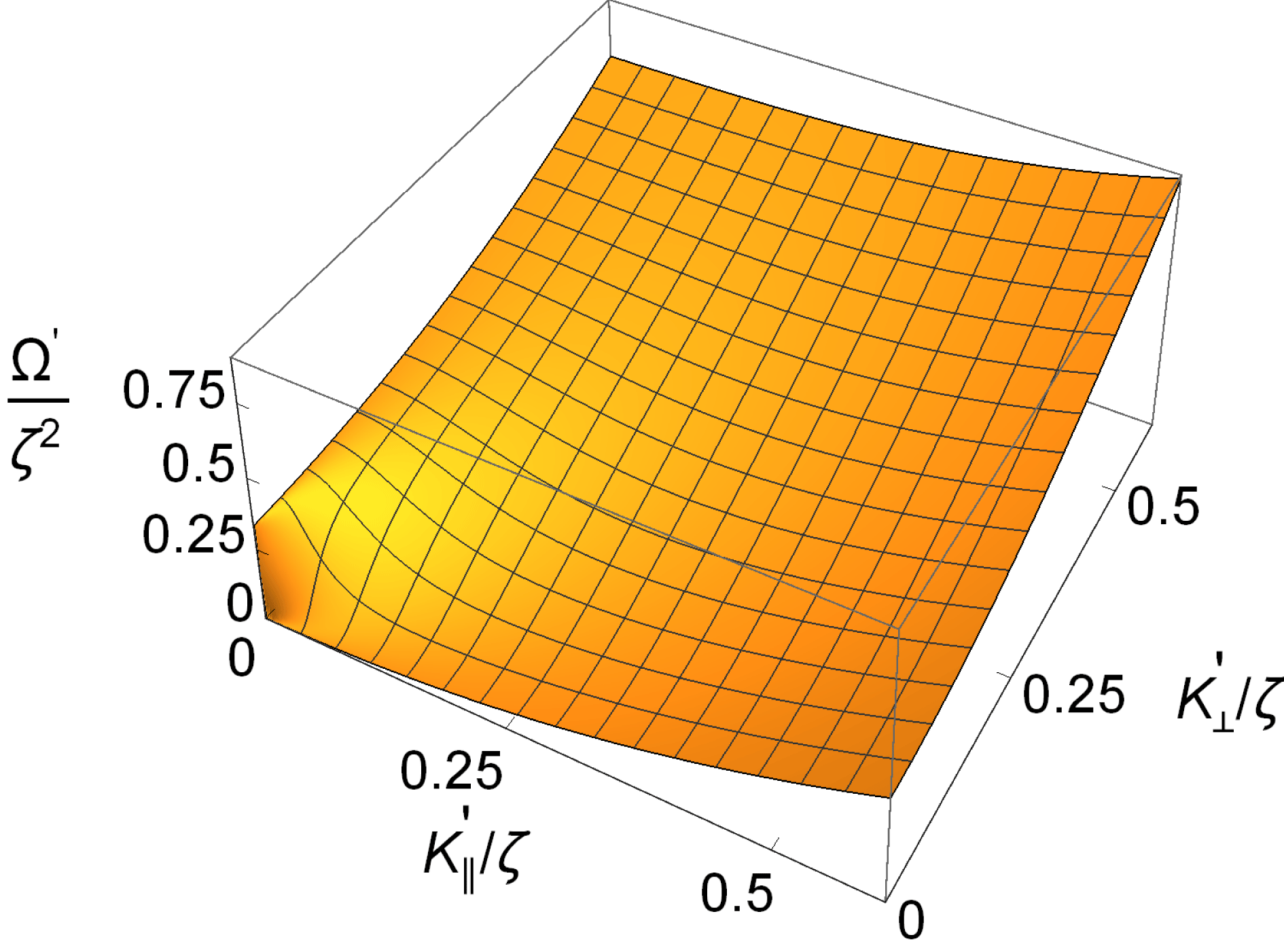
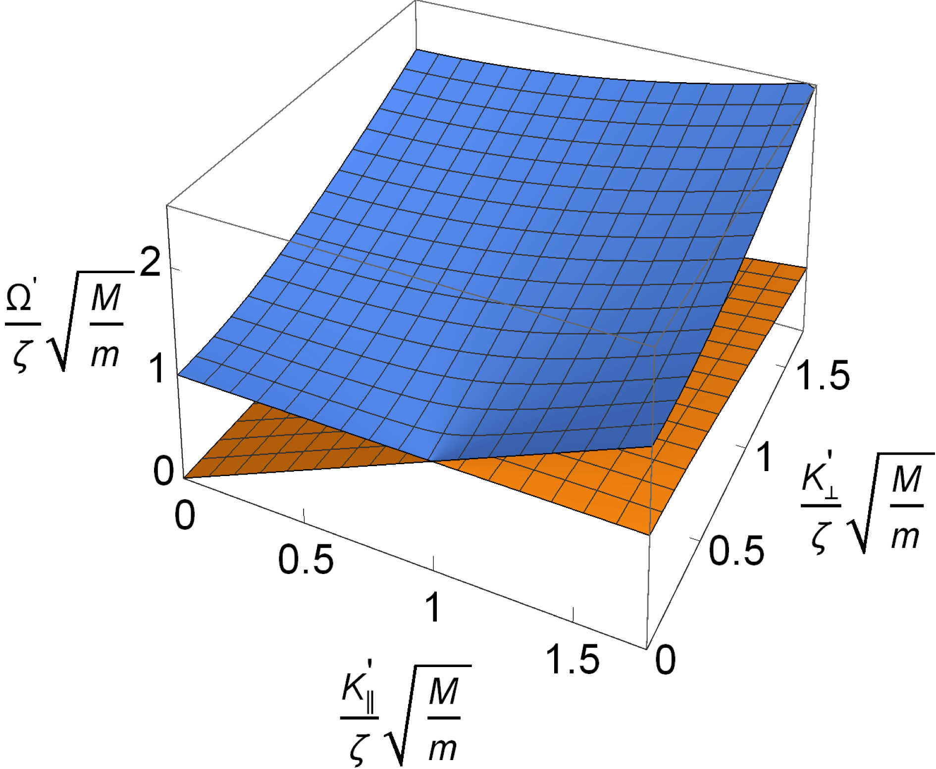
The two wave modes relevant for the present study, electron plasma waves and ion sound and cyclotron waves, are illustrated in figures 1 and 2 using the normalized units. We note that for the electron waves, the effects of the magnetic field are important for
 $K^{\prime }/\unicode[STIX]{x1D701}<1$
; for larger wavenumbers the difference compared to the unmagnetized Langmuir wave case become small. Similarly, we find the magnetic field to be important for the ion dynamics only for normalized frequencies
 $\unicode[STIX]{x1D6FA}^{\prime }$
of the order of
 $\unicode[STIX]{x1D701}\sqrt{m/M}$
or smaller. The relevance of lower hybrid waves will be discussed in § 6.
The approximate electron wave dispersion relation for weakly magnetized plasmas, here shown in normalized units,
 $\unicode[STIX]{x1D6FA}^{\prime }=K^{\prime 2}+(1/3)\unicode[STIX]{x1D701}^{2}K_{\bot }^{\prime 2}/K^{\prime 2}$
. Recall that the basic reference frequency
 $\unicode[STIX]{x1D714}_{\text{pe}}$
has been subtracted.

Ion wave dispersion relation in normalized units for weakly magnetized plasmas where
 $\unicode[STIX]{x1D6FA}_{\text{ci}}<\unicode[STIX]{x1D6FA}_{\text{pi}}$
, see (2.5).

With these normalizations the dispersion relation (3.17) is reduced to
 $$\begin{eqnarray}\unicode[STIX]{x1D6FC}_{L}^{\prime }(\boldsymbol{K}^{\prime },\unicode[STIX]{x1D6FA}^{\prime })=\int \text{d}\boldsymbol{K}_{1}^{\prime }\frac{[\boldsymbol{K}_{1}^{\prime }\boldsymbol{\cdot }(\boldsymbol{K}_{1}^{\prime }-\boldsymbol{K}^{\prime })]^{2}G(\boldsymbol{K}_{1}^{\prime })}{\unicode[STIX]{x1D6FC}_{H}^{\prime }(\boldsymbol{K}_{1}^{\prime }-\boldsymbol{K}^{\prime },\unicode[STIX]{x1D6FA}_{H}^{\prime }(\boldsymbol{K}_{1}^{\prime })-\unicode[STIX]{x1D6FA}^{\prime })}.\end{eqnarray}$$
Here
 $\boldsymbol{K}^{\prime }$
and
 $\unicode[STIX]{x1D6FA}^{\prime }$
can be replaced by
 $-\boldsymbol{K}^{\prime }$
and
 $-\unicode[STIX]{x1D6FA}^{\prime }$
to give
 $$\begin{eqnarray}\unicode[STIX]{x1D6FC}_{L}^{\prime }(-\boldsymbol{K}^{\prime },-\unicode[STIX]{x1D6FA}^{\prime })=\int \text{d}\boldsymbol{K}_{1}^{\prime }[\boldsymbol{K}_{1}^{\prime }\boldsymbol{\cdot }(\boldsymbol{K}_{1}^{\prime }+\boldsymbol{K}^{\prime })]^{2}\left\{\frac{G(\boldsymbol{K}_{1}^{\prime })}{\unicode[STIX]{x1D6FC}_{H}^{\prime }(\boldsymbol{K}_{1}^{\prime }+\boldsymbol{K}^{\prime },\unicode[STIX]{x1D6FA}_{H}^{\prime }(\boldsymbol{K}_{1}^{\prime })+\unicode[STIX]{x1D6FA}^{\prime })}\right\}.\end{eqnarray}$$
Noting
 $\unicode[STIX]{x1D6FC}_{L}^{\prime }(-\boldsymbol{K}^{\prime },-\unicode[STIX]{x1D6FA}^{\prime })=\unicode[STIX]{x1D6FC}_{L}^{\prime }(\boldsymbol{K}^{\prime },\unicode[STIX]{x1D6FA}^{\prime })$
, we rewrite (4.3) as
 $$\begin{eqnarray}\displaystyle \unicode[STIX]{x1D6FC}_{L}^{\prime }(\boldsymbol{K}^{\prime },\unicode[STIX]{x1D6FA}^{\prime }) & = & \displaystyle \frac{1}{2}\int \text{d}\boldsymbol{K}_{1}^{\prime }\left\{\frac{[\boldsymbol{K}_{1}^{\prime }\boldsymbol{\cdot }(\boldsymbol{K}_{1}^{\prime }-\boldsymbol{K}^{\prime })]^{2}}{\unicode[STIX]{x1D6FC}_{H}^{\prime }(\boldsymbol{K}_{1}^{\prime }-\boldsymbol{K}^{\prime },\unicode[STIX]{x1D6FA}_{H}^{\prime }(\boldsymbol{K}_{1}^{\prime })-\unicode[STIX]{x1D6FA}^{\prime })}\right.\nonumber\\ \displaystyle & & \displaystyle +\left.\frac{[\boldsymbol{K}_{1}^{\prime }\boldsymbol{\cdot }(\boldsymbol{K}_{1}^{\prime }+\boldsymbol{K}^{\prime })]^{2}}{\unicode[STIX]{x1D6FC}_{H}^{\prime }(\boldsymbol{K}_{1}^{\prime }+\boldsymbol{K}^{\prime },\unicode[STIX]{x1D6FA}_{H}^{\prime }(\boldsymbol{K}_{1}^{\prime })+\unicode[STIX]{x1D6FA}^{\prime })}\right\}G(\boldsymbol{K}_{1}^{\prime }).\end{eqnarray}$$
The latter symmetric form is best suited for describing modulational instabilities. The present § 4.2 summarizes the main analytical results of our study. In the following we illustrate some of the properties of the results.
4.3 Single mode analysis
A plane wave can be seen as a limiting case of a very narrow spectrum. This limit can be analysed by taking
 $G(\boldsymbol{K}^{\prime })=A_{0}^{2}\unicode[STIX]{x1D6FF}(\boldsymbol{K}^{\prime }-\boldsymbol{K}_{0}^{\prime })$
in (4.5). Even though this is a limiting particular case, it seems that even these results are only sparsely covered by the literature (Dysthe et al.
Reference Dysthe, Mjølhus, Pécseli and Stenflo1978; Freund & Papadopoulos Reference Freund and Papadopoulos1980), so we summarize some selected cases here. Analytical results can be obtained, but they are too long to be reproduced. Instead we show some illustrative results.
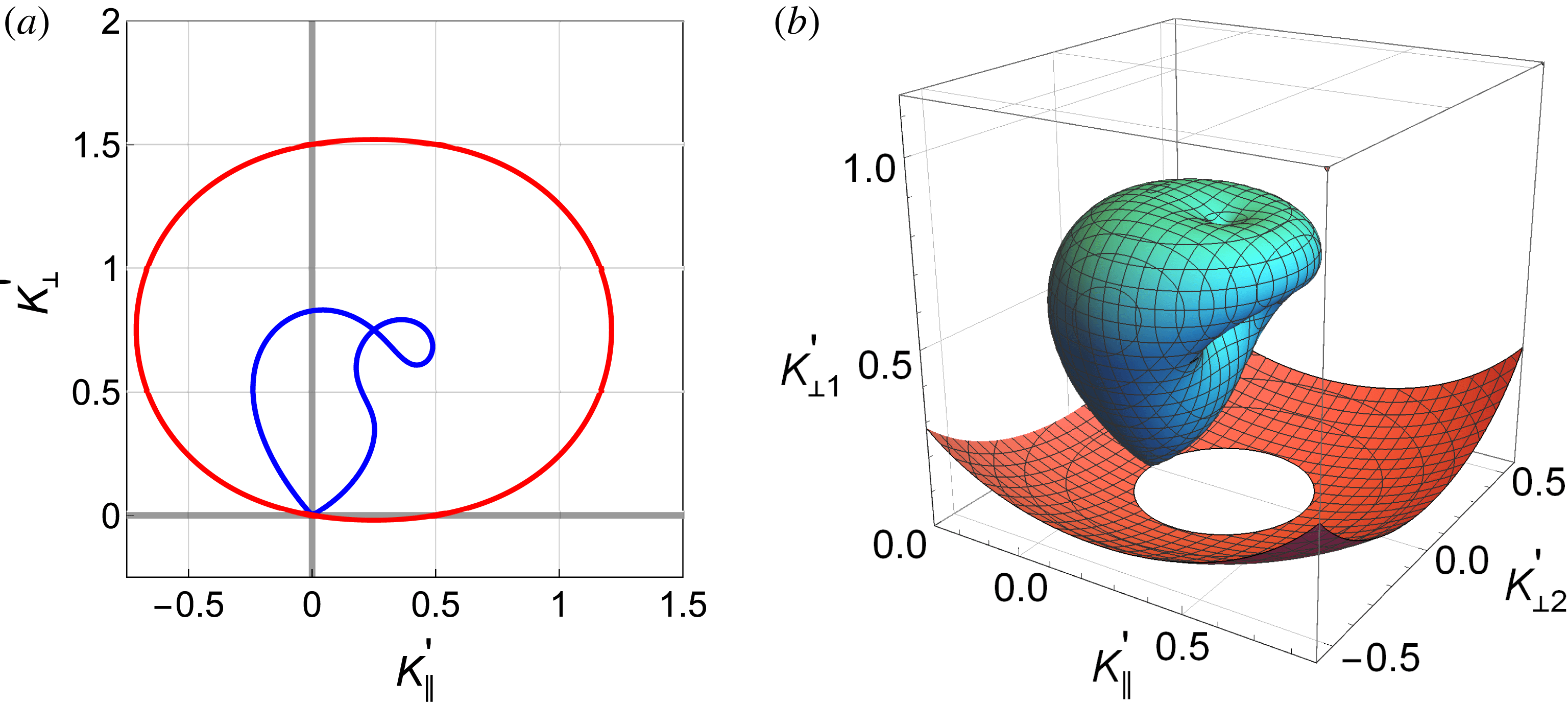
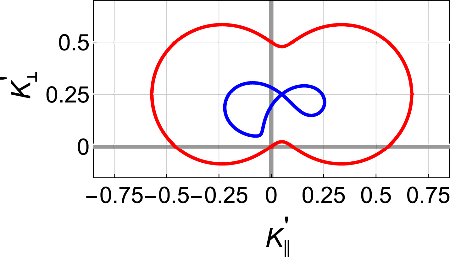
Illustration of the possible wave vectors of the ion waves participating in the decay of electron plasma waves. The nearly elliptical curve corresponds to the low-frequency branch in figure 2, the other curve to the high-frequency branch in that figure. The present illustration has
 $\boldsymbol{K}_{0}^{\prime }\equiv \{K_{0\Vert }^{\prime },0,K_{0\bot }^{\prime }\}=\{0.25,0,0.75\}$
in normalized units. For illustration we use
 $\unicode[STIX]{x1D701}=1$
and a mass ratio of
 $M/m=1600$
. Figure (a) represents a cut at
 $K_{\bot 2}^{\prime }=0$
in the fully three-dimensional figure (b). The two components of
 $\boldsymbol{K}_{\bot }^{\prime }$
are denoted
 $K_{\bot 1}^{\prime }$
and
 $K_{\bot 2}^{\prime }$
on this figure.

4.3.1 Parametric decay
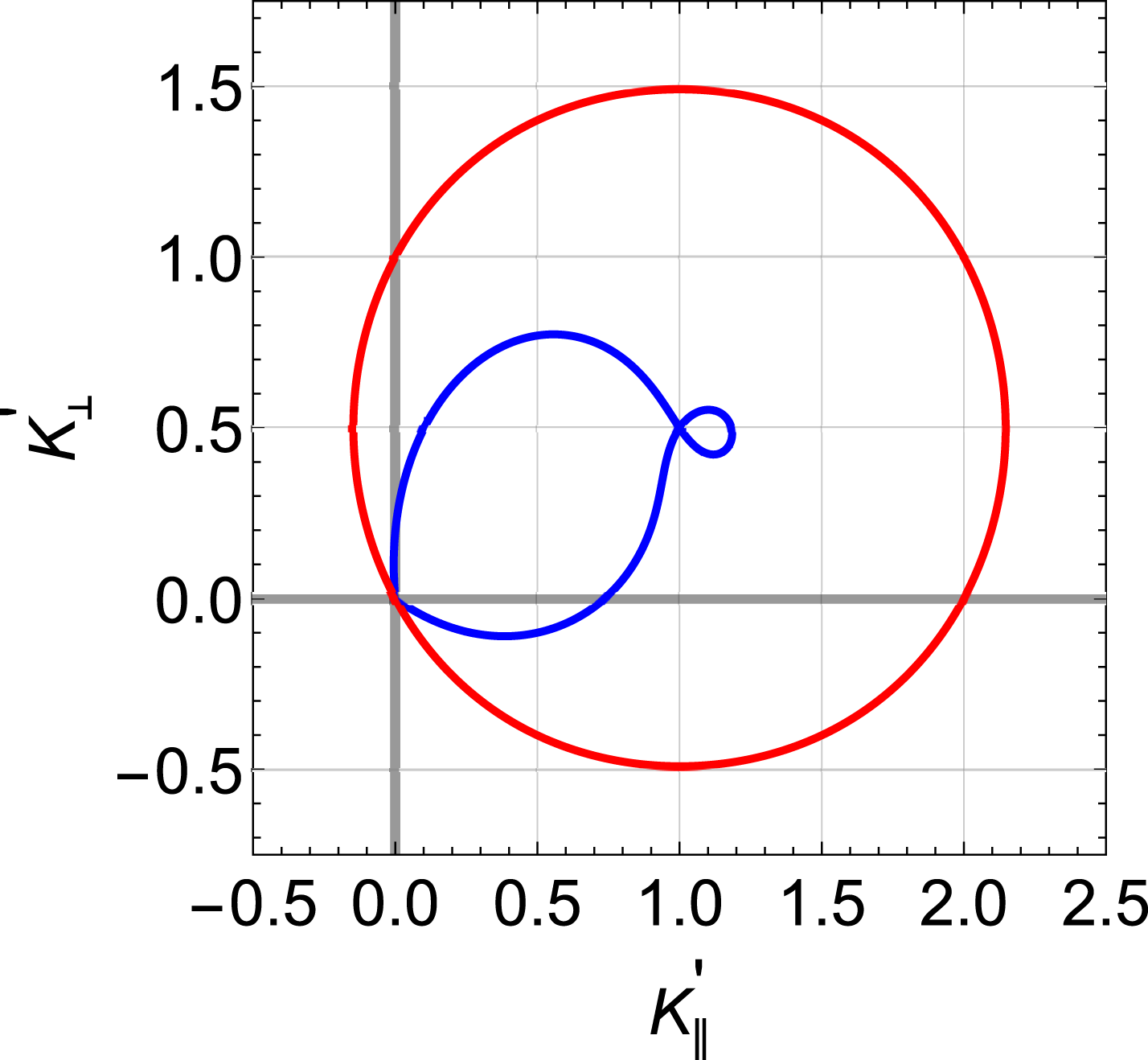
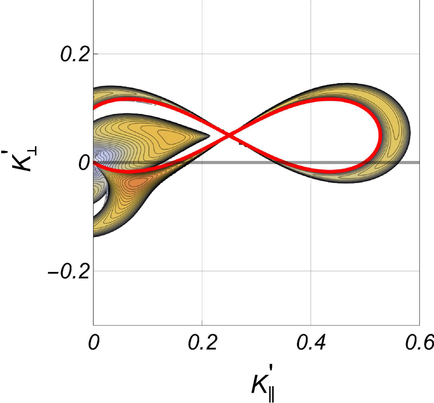
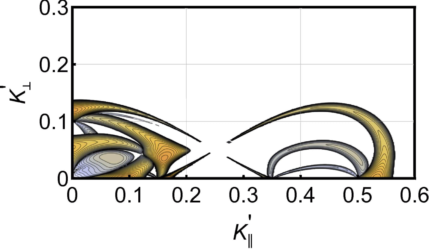
One basic nonlinear wave phenomenon accounted for by our basic relation (4.5) is the decay of electron plasma waves to another electron plasma wave and one of the ion wave branches seen in figure 2, the process subject to wavenumber and frequency matching conditions. In figures 3 and 4 we show two examples for the wave vectors of the ion waves participating in such a decay, given an initial plane electron plasma wave with wavenumber
 $\boldsymbol{K}_{0}^{\prime }$
, where the corresponding frequency
 $\unicode[STIX]{x1D6FA}_{0}$
is found from the dispersion relation, see for instance figure 1. The corresponding values for the electron plasma ‘daughter’ wave is found by the wavenumber matching conditions. It is instructive to compare these result with those found for the simpler Langmuir wave decay in unmagnetized plasmas (Kono & Pécseli Reference Kono and Pécseli2016). As a reminder of the three-dimensional nature of the problem, we inserted in figure 3 a presentation of a part of the ion wave decay vectors in a fully three-dimensional wave vector space. It is important to note that the possibility of decay does not imply that the decay will actually occur, and also we will in general have a decay rate that varies along the curves.
Illustration of the possible wave vectors of the ion waves participating in the decay of electron plasma waves, to be compared with figure 3. The present illustration has
 $\boldsymbol{K}_{0}^{\prime }=\{1.0,0,0.5\}$
in normalized units. The figure represents a cut in a three-dimensional presentation as in figure 3.

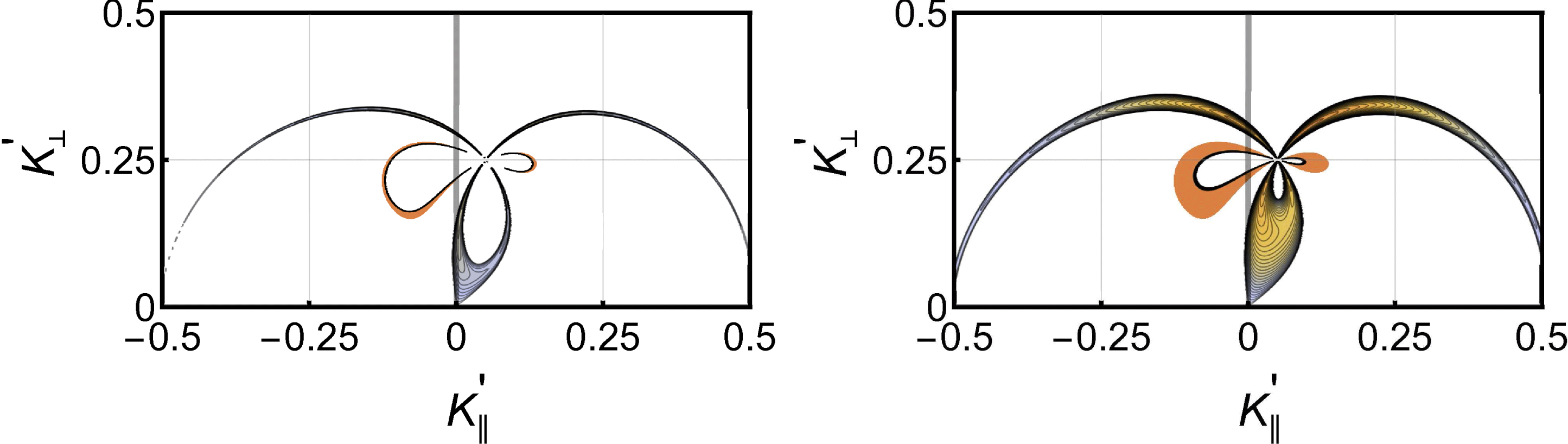
Illustration of the normalized growth rate for the parametric decay corresponding to figure 3 for the case where
 $A_{0}^{2}=0.005$
, see also figure 4. The maximum contour level for the growth rate is here
 $\text{Im}\{\unicode[STIX]{x1D6FA}^{\prime }\}=0.025$
in normalized units. We take
 $\unicode[STIX]{x1D701}=1$
.

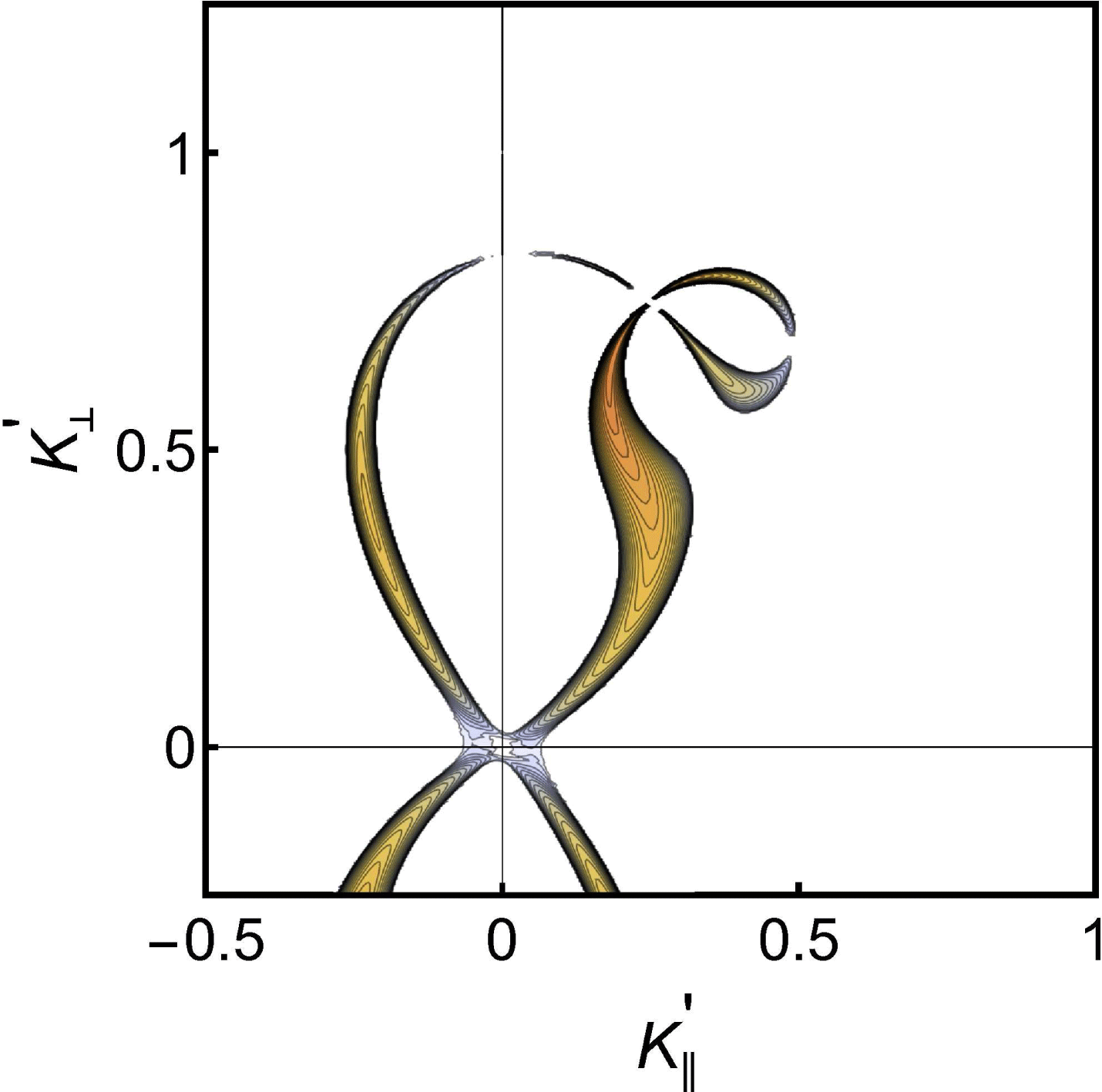
Solutions of the growth rate derived from the dispersion relation are shown in figures 5 and 6 for a selected set of parameters. Most of the relevant information is found in the plane spanned by
 $\boldsymbol{B}_{0}$
and
 $\boldsymbol{K}_{0}^{\prime }$
. Only the imaginary part
 $\text{Im}\{\unicode[STIX]{x1D6FA}^{\prime }\}$
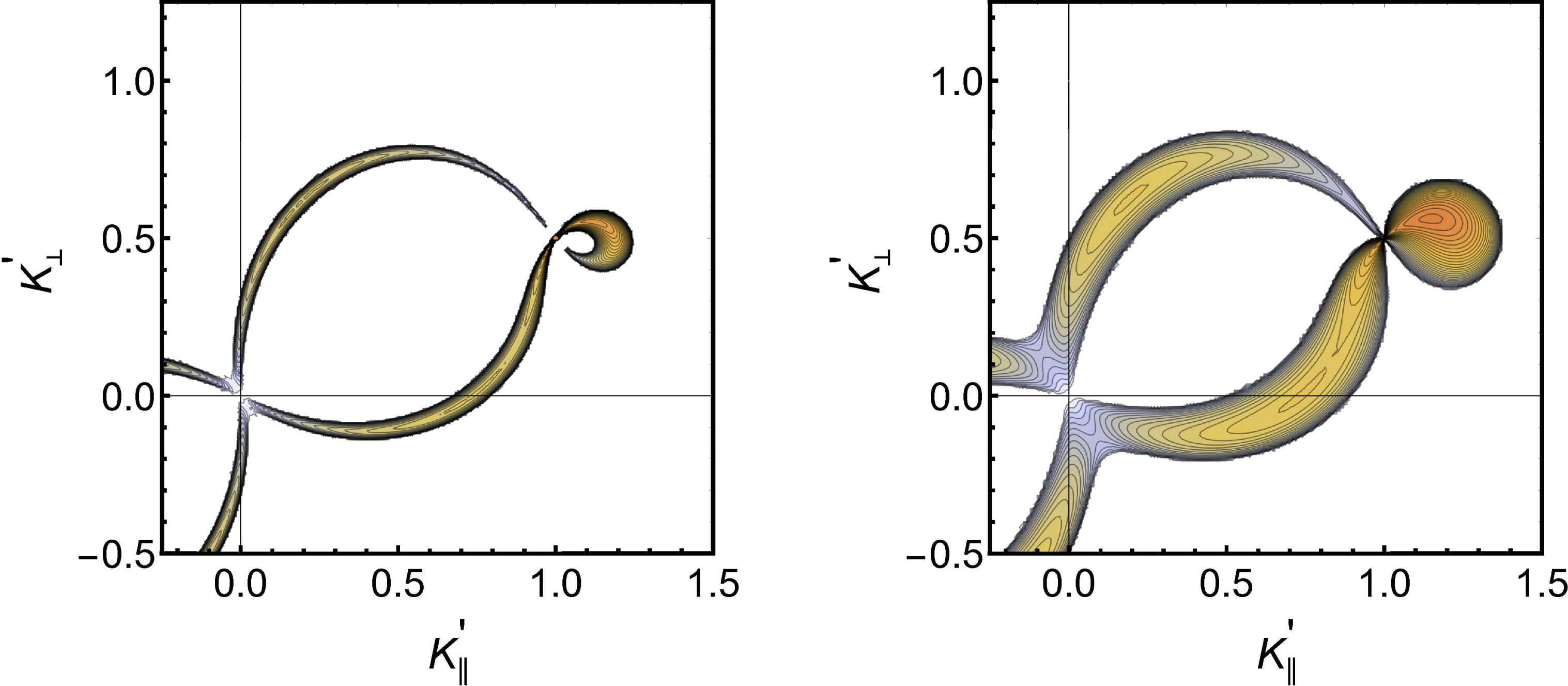
is shown as the information in the real part is comparatively less important. In figures 5 and 6 we readily recognize the inner curve from figure 3, but there seems to be no decay to the outer elliptical branch. We found that this is due to the weak magnetic field limit considered in the present analysis. If we reduce the mass ratio to an artificially small number we find that also this branch becomes excited. A supplementary figure 7 shows results for a different carrier wave vector
 $\boldsymbol{K}_{0}^{\prime }$
.
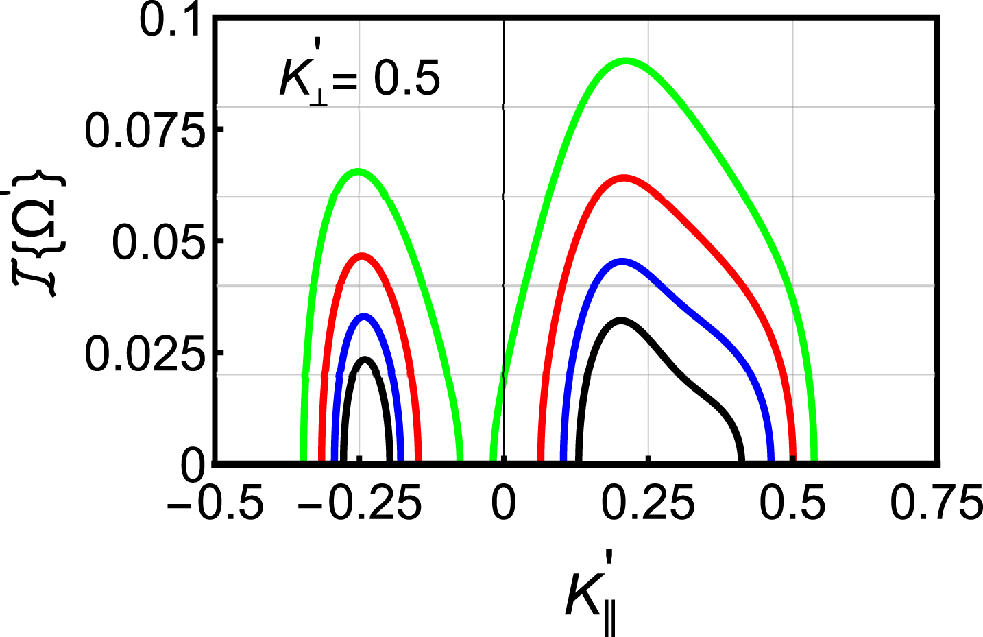
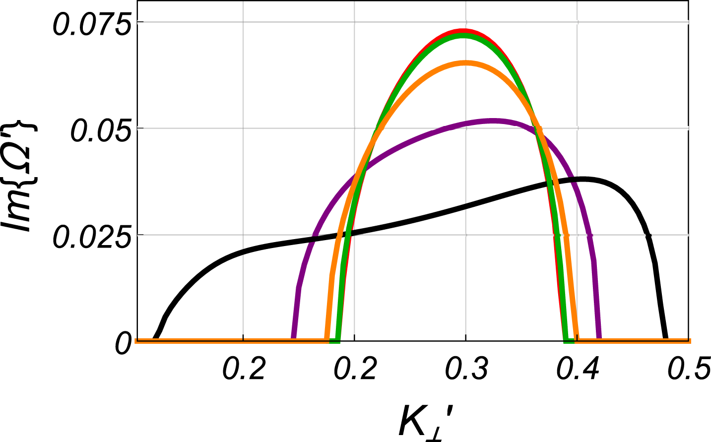
Illustration of the growth rate for varying
 $K_{\Vert }^{\prime }$
, and selected amplitudes, here
 $A_{0}^{2}=0.0125,0.025,0.05,0.1$
sampled at a constant
 $K_{\bot }^{\prime }=0.5$
, i.e. along a horizontal line in figure 5. The parameters correspond otherwise to those in figure 5. The peak value of the growth rate scales as
 $A_{0}$
to a good approximation. We find the same scaling for the width, at least for small
 $A_{0}$
.

Illustrations of the growth rate for the parametric decay corresponding to figure 4 for two amplitudes,
 $A_{0}^{2}=0.005$
and
 $A_{0}^{2}=0.05$
. The maximum contour levels are 0.05 and 0.15, respectively, in normalized units.

In particular, in figure 6 we show the variation of local peak value of the normalized growth rate
 $\text{Im}\{\unicode[STIX]{x1D6FA}^{\prime }\}$
for selected amplitudes
 $A_{0}^{2}$
, for a fixed value of
 $K_{\bot }^{\prime }$
. To a good approximation we find the variation
 $\text{Im}\{\unicode[STIX]{x1D6FA}^{\prime }\}\sim A_{0}$
for
 $A_{0}^{2}\leqslant 0.5$
for this and other examples studied. The result is consistent with what is found for the unmagnetized case (Thornhill & ter Haar Reference Thornhill and ter Haar1978; Kono & Pécseli Reference Kono and Pécseli2016). The figure also illustrates the nonlinear line broadening for increasing
 $A_{0}^{2}$
. Enhancing the wave amplitude further than the range shown on the figure we find the two modes of propagation to merge into one broad line. The decay curves in figures 3 and 4 are curves in a three-dimensional wave vector space. Due to the finite bandwidth, the growth rates illustrated in figures 5–7 represent ‘cuts’ in a three-dimensional volume in a wave vector space. The same comment applies to a number of figures in the following.
4.3.2 Modulational instability
The results presented so far refer to parametric decay of electron plasma waves. The frequency and wave vector matching condition is here sufficient to give the contours for the decay, and only the growth rate of the decay instability needs to be determined. Modulational instabilities are of a different nature. This is a four wave process, and the decay product is no longer a wave mode satisfying a dispersion relation. Our dispersion relation (4.5) accounts for both decay and modulational instabilities.
For unmagnetized waves in the small amplitude limit the separation between decay and modulational instabilities is straight forward, at least as long as a fluid model is used. The point is here that modulational instabilities are found when the perturbations in plasma density is in counter-phase with the spatial variation of
 $|E|^{2}$
. This happens when a wave packet or a spatially modulated wavetrain propagates at a speed below
 $C_{s}$
. With the normalization used here this conditions implies
 $K^{\prime }<1/2$
for modulational instabilities in unmagnetized plasmas. The sign of the phase relation (in phase or counter-phase) is in this case given be the sign of
 $u_{g}^{2}-C_{s}^{2}$
, where
 $u_{g}$
is the group velocity of the Langmuir wave. The finite line width for increasing amplitudes ‘blurs’ the separation between modulational and decay instabilities (Kono & Pécseli Reference Kono and Pécseli2016). Similarly, a kinetic ion model will imply a complex relationship between perturbations in plasma density and the Miller force, and also in this case the range of decay and modulational instability will overlap.
For magnetized plasmas the topology of the problem can in general be more complicated (Dysthe et al.
Reference Dysthe, Mjølhus, Pécseli and Stenflo1978; Dysthe & Pécseli Reference Dysthe and Pécseli1978), and now contains too many parameters to allow presentation in a simple diagram. We present here an example where
 $\boldsymbol{K}_{0}^{\prime }=\{0.05,0,0.25\}$
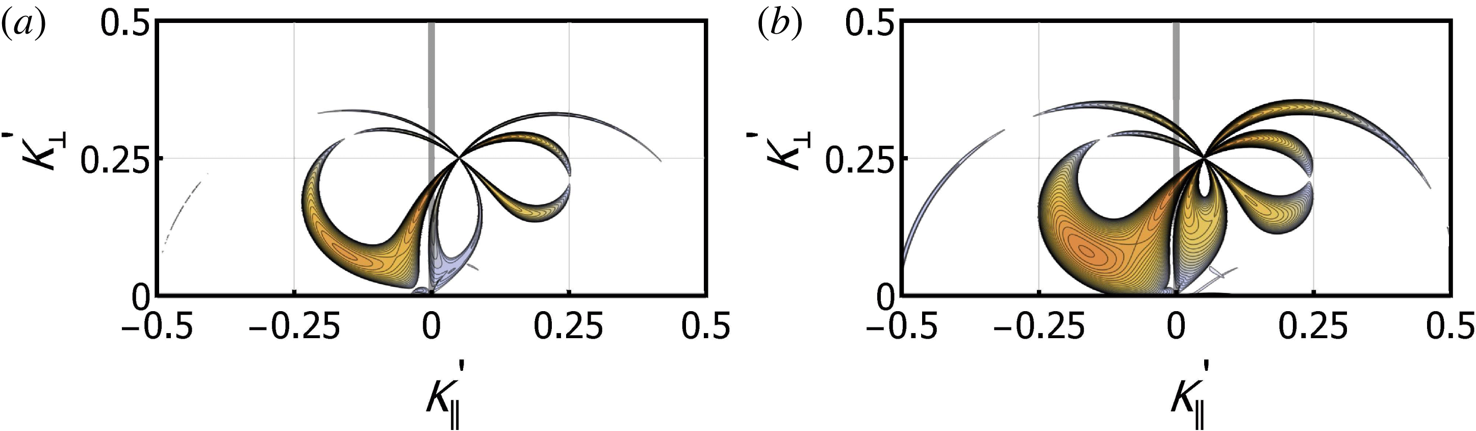
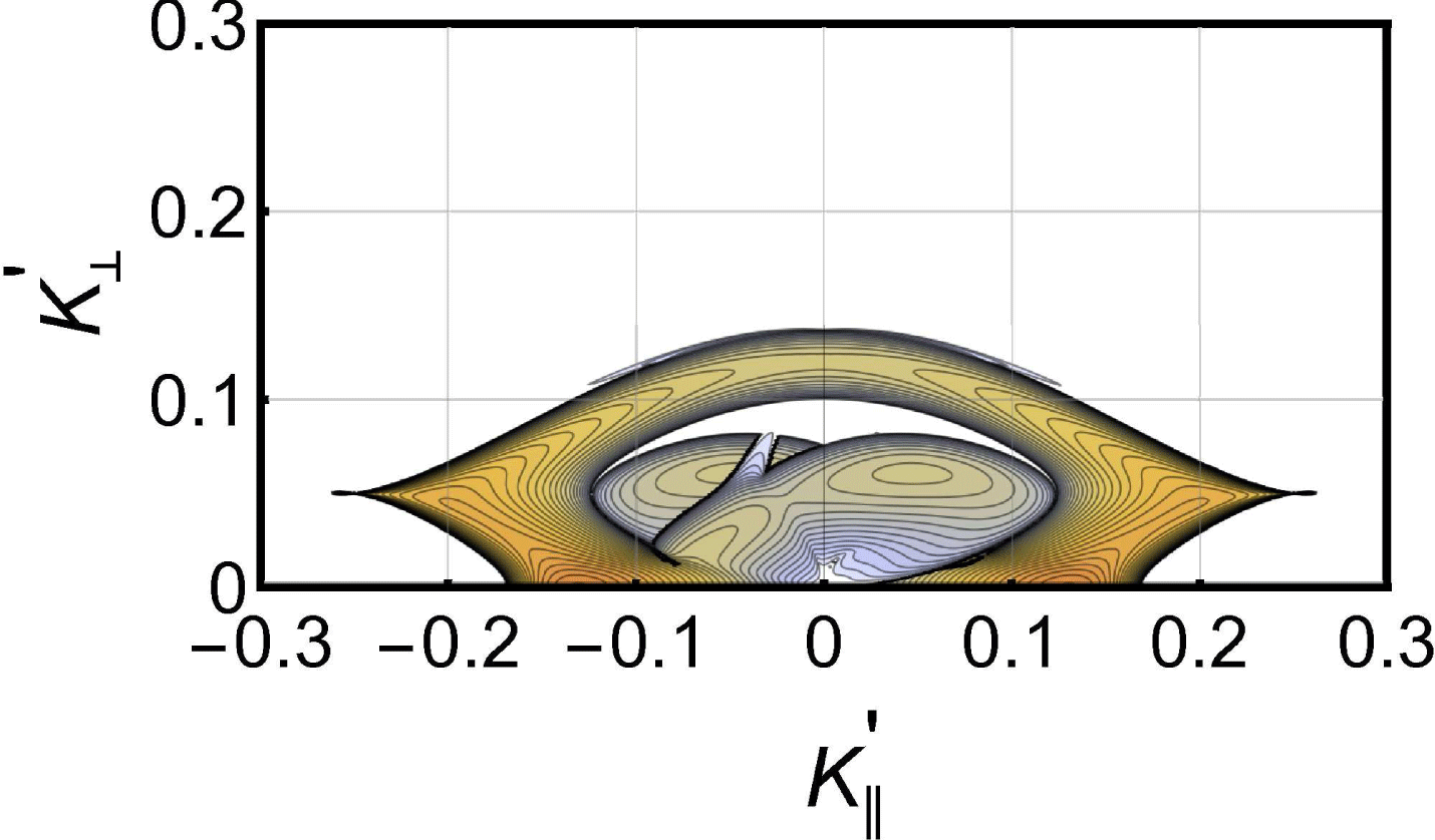
in normalized units, see figure 8. For reference we show in figure 9 the decay products for theses parameters. We recognize in figure 8 the decay to the high-frequency ion branch, but find also here that the decay to the low-frequency branch is absent. In addition we find in figure 8 a growth rate for another mode type, the modulational instability. We thus find here a coexistence of decay and modulational instabilities. This coexistence has no counterpart in fluid models of unmagnetized weakly nonlinear electron plasma waves, as mentioned. We found that the growth rates for fixed
 $A_{0}^{2}$
become significantly reduced when the magnitude of wavenumber of the ‘mother wave’ is reduced. This feature is readily explained by noting that
 $A_{0}^{2}$
is the mean square of the potential of the electrostatic wave field, while it is the electric field that enters the nonlinear driving term,
 $E_{0}^{2}=(K_{0}A_{0})^{2}$
.
Illustration of a case with coexistence of parametric decay and modulational instability for
 $\boldsymbol{K}_{0}^{\prime }=\{0.05,0,0.25\}$
with two amplitudes
 $A_{0}^{2}=0.1$
and
 $A_{0}^{2}=0.5$
. A small wavenumber component
 $K_{0\Vert }^{\prime }=0.05$
is included to break the symmetry. The maximum contours shown are at
 $\text{Im}\{\unicode[STIX]{x1D6FA}^{\prime }\}=0.015$
and
 $\text{Im}\{\unicode[STIX]{x1D6FA}^{\prime }\}=0.03$
in (a) and (b), respectively.

Decay diagram for the case where
 $\boldsymbol{K}_{0}^{\prime }=\{0.05,0,0.25\}$
, see also figure 8.

In order to give analytical estimates for the growth rates of the modulational instabilities we rewrite the dispersion relation by introducing
 $$\begin{eqnarray}\unicode[STIX]{x1D6FA}_{L\pm }^{\prime }(\boldsymbol{K}^{\prime })\equiv \frac{1}{\sqrt{2}}\sqrt{K^{\prime ^{2}}+\frac{m}{M}\unicode[STIX]{x1D701}^{2}\pm \sqrt{\frac{m^{2}}{M^{2}}\unicode[STIX]{x1D701}^{4}+K^{\prime 4}-2\frac{m}{M}\unicode[STIX]{x1D701}^{2}(K^{\prime ^{2}}-2K_{\bot }^{\prime 2})}},\end{eqnarray}$$
and
 $$\begin{eqnarray}\unicode[STIX]{x1D6FA}_{H}^{\prime }(\boldsymbol{K}^{\prime })\equiv K^{\prime 2}+\frac{1}{3}\unicode[STIX]{x1D701}^{2}\frac{K_{\bot }^{\prime 2}}{K^{\prime 2}},\end{eqnarray}$$
and we can for instance write
 $\unicode[STIX]{x1D6FC}_{H}^{\prime }(\boldsymbol{K}^{\prime },\unicode[STIX]{x1D6FA}^{\prime })=[\unicode[STIX]{x1D6FA}^{\prime }-\unicode[STIX]{x1D6FA}_{H}^{\prime }(\boldsymbol{K}^{\prime })]K^{\prime 2}$
, see figure 1 for illustration. We use also the abbreviation
 $\unicode[STIX]{x1D6FA}_{0}^{\prime }(\boldsymbol{K}^{\prime })\equiv \sqrt{(m/M)\unicode[STIX]{x1D701}^{2}K_{\bot }^{\prime 2}/K^{\prime 2}}$
. With this notation we can write the dispersion relation for the perturbation of one single mode
 $A_{0}^{2}\unicode[STIX]{x1D6FF}(\boldsymbol{K}^{\prime }-\boldsymbol{K}_{0}^{\prime })$
as
 $$\begin{eqnarray}\displaystyle & & \displaystyle \frac{(\unicode[STIX]{x1D6FA}^{\prime 2}-\unicode[STIX]{x1D6FA}_{L-}^{\prime 2}(\boldsymbol{K}^{\prime }))(\unicode[STIX]{x1D6FA}^{\prime 2}-\unicode[STIX]{x1D6FA}_{L+}^{\prime 2}(\boldsymbol{K}^{\prime }))}{\displaystyle \unicode[STIX]{x1D6FA}^{\prime 2}-\frac{m}{M}\unicode[STIX]{x1D701}^{2}+\unicode[STIX]{x1D6FA}_{0}^{\prime 2}(\boldsymbol{K}^{\prime })}\nonumber\\ \displaystyle & & \displaystyle \quad =A_{0}^{2}\frac{K^{\prime 2}}{2}\left(\frac{[\boldsymbol{K}_{0}^{\prime }\boldsymbol{\cdot }(\boldsymbol{K}_{0}^{\prime }-\boldsymbol{K}^{\prime })]^{2}}{(\boldsymbol{K}_{0}^{\prime }-\boldsymbol{K}^{\prime })^{2}}\frac{1}{\unicode[STIX]{x1D6FA}_{H}^{\prime }(\boldsymbol{K}_{0}^{\prime })-\unicode[STIX]{x1D6FA}^{\prime }-\unicode[STIX]{x1D6FA}_{H}^{\prime }(\boldsymbol{K}_{0}^{\prime }-\boldsymbol{K}^{\prime })}\right.\nonumber\\ \displaystyle & & \displaystyle \qquad +\left.\frac{[\boldsymbol{K}_{0}^{\prime }\boldsymbol{\cdot }(\boldsymbol{K}_{0}^{\prime }+\boldsymbol{K}^{\prime })]^{2}}{(\boldsymbol{K}_{0}^{\prime }+\boldsymbol{K}^{\prime })^{2}}\frac{1}{\unicode[STIX]{x1D6FA}_{H}^{\prime }(\boldsymbol{K}_{0}^{\prime })+\unicode[STIX]{x1D6FA}^{\prime }-\unicode[STIX]{x1D6FA}_{H}^{\prime }(\boldsymbol{K}_{0}^{\prime }+\boldsymbol{K}^{\prime })}\right).\end{eqnarray}$$
We can rewrite (4.8) as
 $$\begin{eqnarray}\displaystyle & & \displaystyle (\unicode[STIX]{x1D6FA}^{\prime }+\unicode[STIX]{x1D6FA}_{H}^{\prime }(\boldsymbol{K}_{0}^{\prime })-\unicode[STIX]{x1D6FA}_{H}^{\prime }(\boldsymbol{K}_{0}^{\prime }+\boldsymbol{K}^{\prime }))(\unicode[STIX]{x1D6FA}^{\prime }-\unicode[STIX]{x1D6FA}_{H}^{\prime }(\boldsymbol{K}_{0}^{\prime })+\unicode[STIX]{x1D6FA}_{H}^{\prime }(\boldsymbol{K}_{0}^{\prime }-\boldsymbol{K}^{\prime }))\nonumber\\ \displaystyle & & \displaystyle \quad =-A_{0}^{2}\frac{K^{\prime 2}}{2}\left(\frac{[\boldsymbol{K}_{0}^{\prime }\boldsymbol{\cdot }(\boldsymbol{K}_{0}^{\prime }-\boldsymbol{K}^{\prime })]^{2}}{(\boldsymbol{K}_{0}^{\prime }-\boldsymbol{K}^{\prime })^{2}}(\unicode[STIX]{x1D6FA}^{\prime }+\unicode[STIX]{x1D6FA}_{H}^{\prime }(\boldsymbol{K}_{0}^{\prime })-\unicode[STIX]{x1D6FA}_{H}^{\prime }(\boldsymbol{K}_{0}^{\prime }+\boldsymbol{K}^{\prime }))\right.\nonumber\\ \displaystyle & & \displaystyle \qquad -\left.\frac{[\boldsymbol{K}_{0}^{\prime }\boldsymbol{\cdot }(\boldsymbol{K}_{0}^{\prime }+\boldsymbol{K}^{\prime })]^{2}}{(\boldsymbol{K}_{0}^{\prime }+\boldsymbol{K})^{\prime 2}}(\unicode[STIX]{x1D6FA}^{\prime }-\unicode[STIX]{x1D6FA}_{H}^{\prime }(\boldsymbol{K}_{0}^{\prime })+\unicode[STIX]{x1D6FA}_{H}^{\prime }(\boldsymbol{K}_{0}^{\prime }-\boldsymbol{K}^{\prime }))\right)\nonumber\\ \displaystyle & & \displaystyle \qquad \times \,\frac{\displaystyle \unicode[STIX]{x1D6FA}^{\prime 2}-\frac{m}{M}\unicode[STIX]{x1D701}^{2}+\unicode[STIX]{x1D6FA}_{0}^{\prime 2}(\boldsymbol{K}^{\prime })}{(\unicode[STIX]{x1D6FA}^{\prime 2}-\unicode[STIX]{x1D6FA}_{L-}^{\prime 2}(\boldsymbol{K}^{\prime }))(\unicode[STIX]{x1D6FA}^{\prime 2}-\unicode[STIX]{x1D6FA}_{L+}^{\prime 2}(\boldsymbol{K}^{\prime }))}.\end{eqnarray}$$
With a little algebra we can rewrite the left-hand side of (4.9) as
 $$\begin{eqnarray}\displaystyle & & \displaystyle (\unicode[STIX]{x1D6FA}^{\prime }+\unicode[STIX]{x1D6FA}_{H}^{\prime }(\boldsymbol{K}_{0}^{\prime })-\unicode[STIX]{x1D6FA}_{H}^{\prime }(\boldsymbol{K}_{0}^{\prime }+\boldsymbol{K}^{\prime }))(\unicode[STIX]{x1D6FA}^{\prime }-\unicode[STIX]{x1D6FA}_{H}^{\prime }(\boldsymbol{K}_{0}^{\prime })+\unicode[STIX]{x1D6FA}_{H}^{\prime }(\boldsymbol{K}_{0}^{\prime }-\boldsymbol{K}^{\prime }))\nonumber\\ \displaystyle & & \displaystyle \quad =(\unicode[STIX]{x1D6FA}^{\prime }-{\textstyle \frac{1}{2}}[\unicode[STIX]{x1D6FA}_{H}^{\prime }(\boldsymbol{K}_{0}^{\prime }+\boldsymbol{K}^{\prime })-\unicode[STIX]{x1D6FA}_{H}^{\prime }(\boldsymbol{K}_{0}^{\prime }-\boldsymbol{K}^{\prime })])^{2}\nonumber\\ \displaystyle & & \displaystyle \qquad -\,(\unicode[STIX]{x1D6FA}_{H}^{\prime }(\boldsymbol{K}_{0}^{\prime })-{\textstyle \frac{1}{2}}[\unicode[STIX]{x1D6FA}_{H}^{\prime }(\boldsymbol{K}_{0}^{\prime }+\boldsymbol{K}^{\prime })+\unicode[STIX]{x1D6FA}_{H}^{\prime }(\boldsymbol{K}_{0}^{\prime }-\boldsymbol{K}^{\prime })])^{2}.\end{eqnarray}$$
As an approximation for small
 $|\boldsymbol{K}^{\prime }|$
we have
 $(1/2)(\unicode[STIX]{x1D6FA}_{H}^{\prime }(\boldsymbol{K}_{0}^{\prime }+\boldsymbol{K}^{\prime })-\unicode[STIX]{x1D6FA}_{H}^{\prime }(\boldsymbol{K}_{0}^{\prime }-\boldsymbol{K}^{\prime }))\approx \boldsymbol{K}^{\prime }\boldsymbol{\cdot }\unicode[STIX]{x1D735}_{\boldsymbol{K}^{\prime }}\unicode[STIX]{x1D6FA}_{H}^{\prime }(\boldsymbol{K}^{\prime })\equiv \boldsymbol{K}^{\prime }\boldsymbol{\cdot }\boldsymbol{u}g(\boldsymbol{K}^{\prime })$
, and similarly
 $(1/2)[\unicode[STIX]{x1D6FA}_{H}^{\prime }(\boldsymbol{K}_{0}^{\prime }+\boldsymbol{K}^{\prime })+\unicode[STIX]{x1D6FA}_{H}^{\prime }(\boldsymbol{K}_{0}^{\prime }-\boldsymbol{K}^{\prime })-2\unicode[STIX]{x1D6FA}_{H}^{\prime }(\boldsymbol{K}_{0}^{\prime })]\approx (1/2)\unicode[STIX]{x1D735}_{\boldsymbol{K}^{\prime }}\unicode[STIX]{x1D735}_{\boldsymbol{K}^{\prime }}\unicode[STIX]{x1D6FA}_{H}^{\prime }(\boldsymbol{K}^{\prime })\boldsymbol{ : }\boldsymbol{K}^{\prime }\boldsymbol{K}^{\prime }$
. As a first approximation we can use
 $\unicode[STIX]{x1D6FA}^{\prime }\approx (1/2)[\unicode[STIX]{x1D6FA}_{H}^{\prime }(\boldsymbol{K}_{0}^{\prime }+\boldsymbol{K}^{\prime })-\unicode[STIX]{x1D6FA}_{H}^{\prime }(\boldsymbol{K}_{0}^{\prime }-\boldsymbol{K}^{\prime })]$
corresponding to wave packets propagating with the group velocity without changing their shape. A slow spatial dispersion of the wave packets is accounted for by the second term. As an approximation we can now write
 $$\begin{eqnarray}\displaystyle & & \displaystyle \unicode[STIX]{x1D6FA}^{\prime }\approx {\textstyle \frac{1}{2}}[\unicode[STIX]{x1D6FA}_{H}^{\prime }(\boldsymbol{K}_{0}^{\prime }+\boldsymbol{K}^{\prime })-\unicode[STIX]{x1D6FA}_{H}^{\prime }(\boldsymbol{K}_{0}^{\prime }-\boldsymbol{K}^{\prime })]\nonumber\\ \displaystyle & & \displaystyle \quad \pm \,\sqrt{(\unicode[STIX]{x1D6FA}_{H}^{\prime }(\boldsymbol{K}_{0}^{\prime })-{\textstyle \frac{1}{2}}(\unicode[STIX]{x1D6FA}_{H}^{\prime }(\boldsymbol{K}_{0}^{\prime }+\boldsymbol{K}^{\prime })+\unicode[STIX]{x1D6FA}_{H}^{\prime }(\boldsymbol{K}_{0}^{\prime }-\boldsymbol{K}^{\prime })))^{2}-{\textstyle \frac{1}{2}}A_{0}^{2}K^{\prime 2}\unicode[STIX]{x1D6FD}(\boldsymbol{K}_{0}^{\prime },\boldsymbol{K}^{\prime })},\qquad\end{eqnarray}$$
where we have defined
 $$\begin{eqnarray}\displaystyle \unicode[STIX]{x1D6FD}(\boldsymbol{K}_{0}^{\prime },\boldsymbol{K}^{\prime }) & \equiv & \displaystyle (\unicode[STIX]{x1D6FA}_{H}^{\prime }(\boldsymbol{K}_{0}^{\prime })-\frac{1}{2}[\unicode[STIX]{x1D6FA}_{H}^{\prime }(\boldsymbol{K}_{0}^{\prime }+\boldsymbol{K}^{\prime })+\unicode[STIX]{x1D6FA}_{H}^{\prime }(\boldsymbol{K}_{0}^{\prime }-\boldsymbol{K}^{\prime })])\nonumber\\ \displaystyle & & \displaystyle \times \,\left(\frac{[\boldsymbol{K}_{0}^{\prime }\boldsymbol{\cdot }(\boldsymbol{K}_{0}^{\prime }-\boldsymbol{K}^{\prime })]^{2}}{(\boldsymbol{K}_{0}^{\prime }-\boldsymbol{K}^{\prime })^{2}}+\frac{[\boldsymbol{K}_{0}^{\prime }\boldsymbol{\cdot }(\boldsymbol{K}_{0}^{\prime }+\boldsymbol{K}^{\prime })]^{2}}{(\boldsymbol{K}_{0}^{\prime }+\boldsymbol{K}^{\prime })^{2}}\right)\nonumber\\ \displaystyle & & \displaystyle \times \,\frac{\displaystyle \frac{1}{4}[\unicode[STIX]{x1D6FA}_{H}^{\prime }(\boldsymbol{K}_{0}^{\prime }+\boldsymbol{K}^{\prime })-\unicode[STIX]{x1D6FA}_{H}^{\prime }(\boldsymbol{K}_{0}^{\prime }-\boldsymbol{K}^{\prime })]^{2}-\frac{m}{M}\unicode[STIX]{x1D701}^{2}+\unicode[STIX]{x1D6FA}_{0}^{\prime 2}(\boldsymbol{K}^{\prime })}{\displaystyle \left(\frac{1}{4}[\unicode[STIX]{x1D6FA}_{H}^{\prime }(\boldsymbol{K}_{0}^{\prime }+\boldsymbol{K}^{\prime })-\unicode[STIX]{x1D6FA}_{H}^{\prime }(\boldsymbol{K}_{0}^{\prime }-\boldsymbol{K}^{\prime })]^{2}-\unicode[STIX]{x1D6FA}_{L-}^{\prime 2}(\boldsymbol{K}^{\prime })\right)}\nonumber\\ \displaystyle & & \displaystyle \times \,\frac{1}{\displaystyle \left(\frac{1}{4}[\unicode[STIX]{x1D6FA}_{H}^{\prime }(\boldsymbol{K}_{0}^{\prime }+\boldsymbol{K}^{\prime })-\unicode[STIX]{x1D6FA}_{H}^{\prime }(\boldsymbol{K}_{0}^{\prime }-\boldsymbol{K}^{\prime })]^{2}-\unicode[STIX]{x1D6FA}_{L+}^{\prime 2}(\boldsymbol{K}^{\prime })\right)}.\end{eqnarray}$$
Provided
 $\unicode[STIX]{x1D6FD}(\boldsymbol{K}_{0}^{\prime },\boldsymbol{K}^{\prime })>0$
we will have instability for sufficiently large values of
 $A_{0}^{2}$
for any
 $(\boldsymbol{K}_{0}^{\prime },\boldsymbol{K}^{\prime })$
. The expression (4.11) has the form, or structure, that is characteristic for modulational instabilities of plane waves (Thornhill & ter Haar Reference Thornhill and ter Haar1978). Apart from a region of small frequencies and wavenumbers we might here ignore
 $\unicode[STIX]{x1D701}^{2}m/M$
. In this limit we have
 $\unicode[STIX]{x1D6FA}_{0}^{\prime 2}(\boldsymbol{K}^{\prime })\approx 0$
,
 $\unicode[STIX]{x1D6FA}_{L+}^{\prime 2}(\boldsymbol{K}^{\prime })\approx K^{\prime 2}$
and
 $\unicode[STIX]{x1D6FA}_{L-}^{\prime 2}(\boldsymbol{K}^{\prime })\approx 0$
thereby simplifying
 $\unicode[STIX]{x1D6FD}(\boldsymbol{K}_{0}^{\prime },\boldsymbol{K}^{\prime })$
. The sign of
 $\unicode[STIX]{x1D6FD}(\boldsymbol{K}_{0}^{\prime },\boldsymbol{K}^{\prime })$
is then determined by the sign of
 $$\begin{eqnarray}\frac{\unicode[STIX]{x1D6FA}_{H}^{\prime }(\boldsymbol{K}_{0}^{\prime })-\frac{1}{2}\left[\unicode[STIX]{x1D6FA}_{H}^{\prime }(\boldsymbol{K}_{0}^{\prime }+\boldsymbol{K}^{\prime })+\unicode[STIX]{x1D6FA}_{H}^{\prime }(\boldsymbol{K}_{0}^{\prime }-\boldsymbol{K}^{\prime })\right]}{[\unicode[STIX]{x1D6FA}_{H}^{\prime }(\boldsymbol{K}_{0}^{\prime }+\boldsymbol{K}^{\prime })-\unicode[STIX]{x1D6FA}_{H}^{\prime }(\boldsymbol{K}_{0}^{\prime }-\boldsymbol{K}^{\prime })]^{2}-4\unicode[STIX]{x1D6FA}_{L+}^{\prime 2}(\boldsymbol{K}^{\prime })}.\end{eqnarray}$$
The sign of the denominator in (4.13) determines the sign of the nonlinear frequency shify as for unmagnetized waves (Dysthe & Pécseli Reference Dysthe and Pécseli1977) through the relative magnitudes of the group velocity and the sound velocity. Recalling the approximation for the group velocity and the wave vector derivative of the group velocity mentioned before, the criterion of
 $\unicode[STIX]{x1D6FD}(\boldsymbol{K}_{0}^{\prime },\boldsymbol{K}^{\prime })>0$
can be seen as an equivalent of the Lighthill criterion (Kadomtsev & Karpman Reference Kadomtsev and Karpman1971) for the modulational instability of a finite amplitude plane wave. The case where the ion magnetization is important is discussed elsewhere (Dysthe et al.
Reference Dysthe, Mjølhus, Pécseli and Stenflo1978; Dysthe & Pécseli Reference Dysthe and Pécseli1978; Pécseli Reference Pécseli1985).
An illustrative result of (4.11) is shown in figure 10 for the parameters corresponding to figure 8. We find the agreement to be satisfactory. The results for the modulational instability are faithfully reproduced, apart from two small lobes that are ‘quenched’ by the decay instability (figure 10, these lobes are saturated in the colour coding). We observed also previously (Kono & Pécseli Reference Kono and Pécseli2016) that in regions where two dispersion relations were close, they were mutually distorted. The analytical expression was tested also on other parameters where the modulational instability could be observed, and the agreement with direct solution of the dispersion relation was good also in these cases. The analytical approximation (4.11) has the amplitude variation
 $\text{Im}\{\unicode[STIX]{x1D6FA}^{\prime }\}\sim A_{0}$
for small
 $A_{0}^{2}$
as found to be standard for modulational instabilities (Thornhill & ter Haar Reference Thornhill and ter Haar1978).


We consider the filamentation instability where
 $\boldsymbol{K}^{\prime }\bot \boldsymbol{K}_{0}^{\prime }$
as a special case of the modulational instability. When
 $\boldsymbol{K}_{0}^{\prime }\Vert \boldsymbol{B}_{0}$
or
 $\boldsymbol{K}_{0}^{\prime }\bot \boldsymbol{B}_{0}$
this instability will be absolute, but can be convective for other directions of
 $\boldsymbol{K}_{0}^{\prime }$
(Shukla Reference Shukla1977). The real part of the frequency will be
 $\boldsymbol{u}_{g}\boldsymbol{\cdot }\boldsymbol{K}^{\prime }$
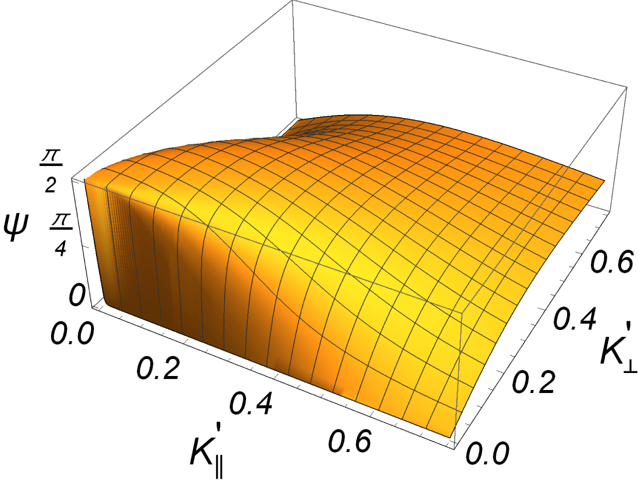
to lowest approximation. In figure 11 we show for reference the angle
 $\unicode[STIX]{x1D713}$
between
 $\boldsymbol{K}_{0}^{\prime }$
and the group velocity
 $\boldsymbol{u}_{g}^{\prime }(\boldsymbol{K}^{\prime })\equiv \unicode[STIX]{x1D735}_{\boldsymbol{K}^{\prime }}\unicode[STIX]{x1D6FA}^{\prime }(\boldsymbol{K}^{\prime })$
.
Angle
 $\unicode[STIX]{x1D713}$
between the group velocity
 $\boldsymbol{u}_{g}^{\prime }(\boldsymbol{K}^{\prime })\equiv \unicode[STIX]{x1D735}_{\boldsymbol{K}^{\prime }}\unicode[STIX]{x1D6FA}^{\prime }(\boldsymbol{K}^{\prime })$
and the wave vector
 $\boldsymbol{K}^{\prime }$
for the electron plasma waves, shown here for the case where
 $\unicode[STIX]{x1D701}=1$
. A singularity at
 $\boldsymbol{K}^{\prime }=\{0,0,0\}$
is caused by the omission of an electromagnetic component.

4.4 Two waves
As the first step towards a spectrum of waves we can consider a superposition of two plane electron plasma waves. Two counter-propagating electron plasma waves have been studied analytically (Pavlenko & Petviashvili Reference Pavlenko and Petviashvili1977) as well as experimentally (Wong & Quon Reference Wong and Quon1975; Michelsen et al. Reference Michelsen, Pécseli, Rasmussen and Sato1977; Leung, Tran & Wong Reference Leung, Tran and Wong1982), so we choose this particular example.
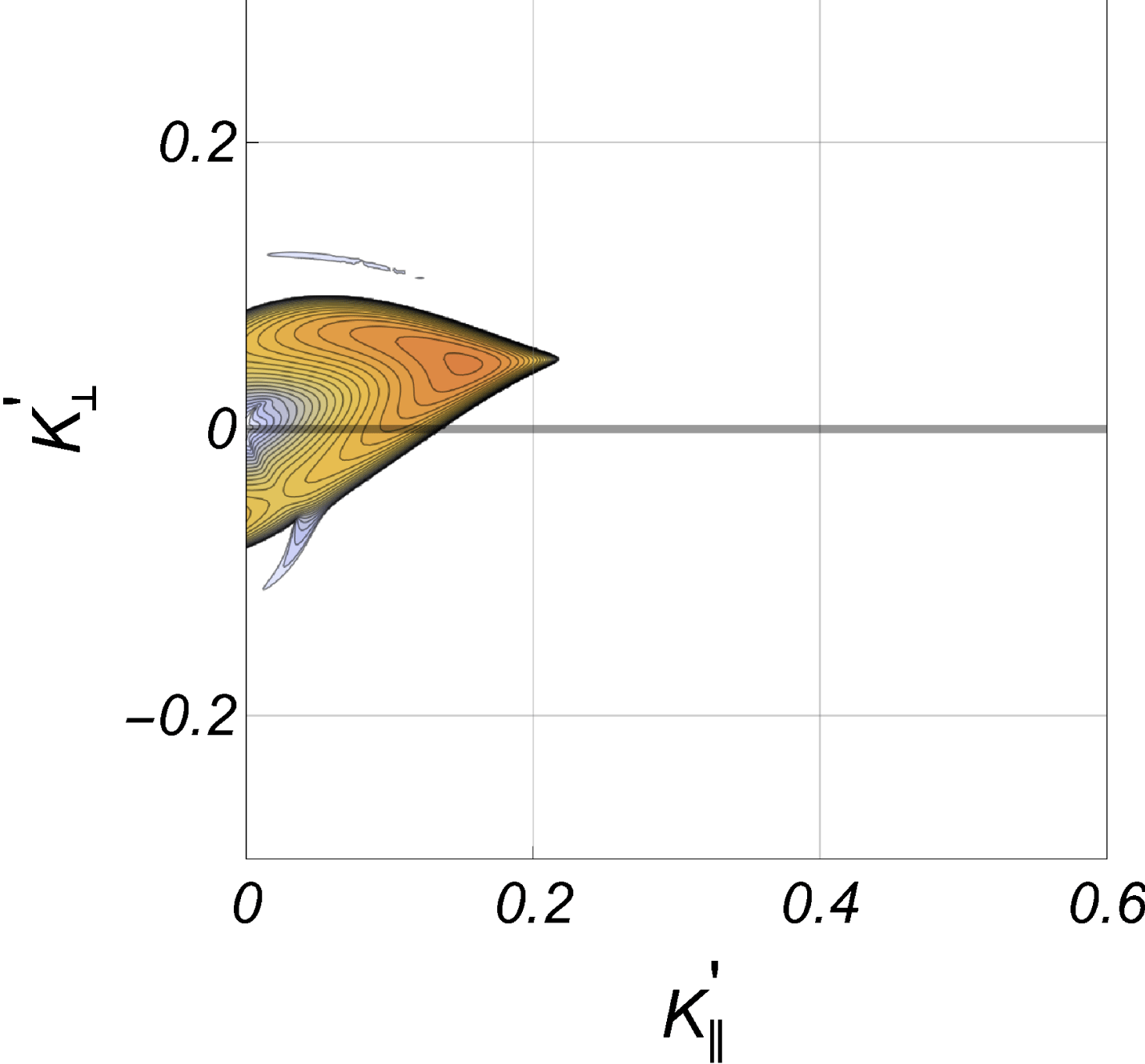
 $\text{Im}\{\unicode[STIX]{x1D6FA}^{\prime }\}$
for a reference plane wave with
 $\boldsymbol{K}_{0}^{\prime }=\{0.25,0,0.05\}$
and
 $A_{0}^{2}=0.5$
. A small wavenumber component
 $\bot \boldsymbol{B}_{0}$
is included to break the symmetry. The maximum contour level is at 0.025. For these parameters we can have no decay to the high-frequency ion branch, and the growth rates shown are for the modulational instability, as confirmed also by (4.11).

 $\text{Im}\{\unicode[STIX]{x1D6FA}^{\prime }\}$
for two counter-propagating plane waves with
 $\boldsymbol{K}_{0}^{\prime }=\pm \{0.25,0,0.05\}$
and equal amplitudes
 $A_{0}^{2}=0.5$
. Superimposed on the figure we have the contour corresponding to the decay into
 $\unicode[STIX]{x1D6FA}_{L-}^{\prime }(\boldsymbol{K}^{\prime })$
in (4.6), as in e.g. figures 3 and 4. See figure 12 for the characteristics of one of the waves entering the construction for the present figure: the colour coding is the same for these two figures. The present figure is symmetric with respect to the origin.

In nature, and the Earth’s ionosphere in particular, we are most likely to find
 $\boldsymbol{K}_{0}^{\prime }$
nearly parallel to
 $\boldsymbol{B}_{0}$
since electron waves are there excited most easily by low density magnetic field aligned electron beams (Guio & Forme Reference Guio and Forme2006) propagating along
 $\boldsymbol{B}_{0}$
. In figure 12 taken together with figure 13 we show a generalization of the single wave case where now the modulational instability dominates. The decay to the high-frequency branch
 $\unicode[STIX]{x1D6FA}_{L+}^{\prime }(\boldsymbol{K}^{\prime })$
is not accessible for the present parameters, and figure 12 for the reference plane wave accounts for the modulational instability only. When we have two waves with twice the net wave energy density, see figure 13, we find a slight modification of the growth rate of the modulational instability as compared to the single mode case. More importantly we observe decay to the low-frequency branch
 $\unicode[STIX]{x1D6FA}_{L-}^{\prime }(\boldsymbol{K}^{\prime })$
in (4.6), which has otherwise not been found in any calculation for a single plane wave. The figure changes if we ignore the magnetic field in the description of the low-frequency ion dynamics. Although it might be tempting to ignore the terms containing
 $m/M$
due to the smallness of the electron–ion mass ratio, we find that for spectra deviating from a single plane wave, this ‘near-zero-frequency’ branch can nonetheless have importance for the nonlinear electron waves in even weakly magnetized plasmas. For most relevant decay products we have wave vectors
 $K>\unicode[STIX]{x1D6FA}_{\text{ci}}/C_{s}$
, implying that the phase velocities associated with this branch are much smaller than
 $C_{s}$
. In the following this will be referred to as ‘the slow mode’. For the relevant particular case with
 $K\sim \sqrt{m/M}/\unicode[STIX]{x1D706}_{\text{De}}$
we find a characteristic velocity for the slow mode to be
 ${\sim}C_{s}(\unicode[STIX]{x1D714}_{\text{ce}}/\unicode[STIX]{x1D714}_{\text{pe}})\ll C_{s}$
for our conditions. Incidentally, we note faint signs of this slow mode being excited already in figure 12, near
 $K_{\bot }^{\prime }\approx 0.1$
 $\text{Im}\{\unicode[STIX]{x1D6FA}^{\prime }\}$
for two counter-propagating plane waves with
 $\boldsymbol{K}_{0}^{\prime }=\{\pm 0.25,0,0.05\}$
and equal amplitudes
 $A_{0}^{2}=0.5$
. The maximum contour level is at 0.03. See again figure 12 for the characteristics of one of the waves entering the construction for the present figure. From
 $\text{Re}\{\unicode[STIX]{x1D6FA}^{\prime }\}$
we find that in the present case the waves are propagating, i.e. they do not correspond to the quasi-stationary mode. The symmetry axis is horizontal at
 $K_{\bot }^{\prime }=0$
in this figure.

When interpreting figure 13 we bear in mind that implicit in the derivation is that the phases of the two waves are random and independent, as implied in what is often termed the ‘random phase approximation’ (Nicholson Reference Nicholson1983; Pécseli Reference Pécseli2014, Reference Pécseli2016). Physically, this can be realized by reflection of a plane wave from a slowly moving or oscillating reflector (Dysthe, Pécseli & Trulsen Reference Dysthe, Pécseli and Trulsen1983).
An interesting interpretation of the slow mode relates to observations of naturally enhanced ion acoustic lines (NEIALs). Here non-thermal asymmetric up and down propagating sound waves are observed, but in addition also an enhanced or anomalous level of slow or stationary plasma density variations are found (Rietveld, Collis & St-Maurice Reference Rietveld, Collis and St-Maurice1991; Buchert et al. Reference Buchert, van Eyken, Ogawa and Watanabe1999; Sedgemore-Schulthess & St-Maurice Reference Sedgemore-Schulthess and St-Maurice2001). An interpretation in terms of strongly nonlinear Langmuir waves has been suggested (Guio & Forme Reference Guio and Forme2006; Isham et al. Reference Isham, Rietveld, Guio, Forme, Grydeland and Mjølhus2012), where localized quasi-stationary wave filled cavities develop. Our results indicate that slow or stationary plasma density variations can be found for weakly magnetized plasmas even for weakly nonlinear electron plasma waves, without cavity formation.
We point out, however, that the slow mode is not excited in all multi-wave cases. We show as an example two obliquely propagating waves with
 $\boldsymbol{K}_{0}^{\prime }=\{\pm 0.05,0,0.25\}$
in figure 14. We find that the decay waves are propagating here. The growth rate of the modulational instability found for one of the plane wave components is on the other hand strongly modified in this case. The results in figure 13 refer to a near ‘head on’ reflection of a wave, while figure 14 corresponds to oblique reflection, reminiscent of, for instance, Lloyd’s single mirror experiment.
4.5 Four waves
With some imposed symmetry conditions it is possible to solve the basic equation also for more than 2 wave modes. As an illustration we show here results for the case where 4 waves are excited with equal amplitudes, where
 $\boldsymbol{K}_{0}^{\prime }=\{\pm 0.05,0,\pm 0.25\}$
, see figure 15. The maximum growth rate is decreased in comparison to the one found for the 2 wave mode case illustrated in figures 13 and 14 which involves the same magnitude of the wavenumber components. Also in figure 15 we find the slow mode to be excited.
Average
 $\text{Im}\{\unicode[STIX]{x1D6FA}^{\prime }\}$
for the case where 4 plane waves are excited with
 $\boldsymbol{K}_{0}^{\prime }=\{\pm 0.25,0,\pm 0.05\}$
and equal amplitudes
 $A_{0}^{2}=0.25$
. The maximum contour level is 0.015. The full figure is symmetric with respect to both the vertical and horizontal axes.

As expected, we find that the increased number of wave modes gives rise to an increasing complexity of the dispersion relation. The most conspicuous new feature of the four wave case is however the excitation of two dispersion relation branches to reach substantial growth rates. The imaginary part of the average of these two branches is shown in figure 15. Also in this case we find excitation of the ‘slow mode’, substantiating the claim that this mode is generated by distributions of wave modes over a substantial region of the wavenumber space, when the average of the wave vectors is at or near the origin
 $\boldsymbol{K}_{0}^{\prime }=\{0,0,0\}$
. A general plausible conclusion from the limited number of cases studied here is that the number of low-frequency modes being excited is increased for increasing number of high frequency modes, covering a wide range in
 $\boldsymbol{K}_{0}^{\prime }$
space. Also the maximum growth rate is decreasing and, as mentioned, we find a possibility for exciting slow modes. These observations were also confirmed by considering a three wave case.
The many mode case has several similarities with the Vlasov equation describing collisionless plasmas. The one mode case corresponds to a single cold beam in such a kinetic model. Addition of many plane waves corresponds to increasing the number of cold beams in the Vlasov model (Marcuvitz Reference Marcuvitz1980; Kontar Reference Kontar2001). Indeed, this similarity has been pursued with some success in numerical simulations (Tappert & Cole Reference Tappert and Cole1971; Pécseli & Trulsen Reference Pécseli and Trulsen1990, Reference Pécseli and Trulsen1992), although seemingly only in a one-dimensional case so far. The analogy with the Vlasov equation is only complete if we ignore the dispersion of the propagating wave packets, i.e. wave packets are only analogous to particles when their dispersion is ignored. This feature is included in the present analysis, as already mentioned, so the present results are more general than those derived from the standard wave kinetic equation (Camac et al. Reference Camac, Kantrowitz, Litvak, Patrick and Petschek1962; Kadomtsev Reference Kadomtsev1965; Vedenov, Gordeev & Rudakov Reference Vedenov, Gordeev and Rudakov1967; Shukla & Farid Reference Shukla and Farid1999). An often used argument for the validity of these quasi-particle models is that for wide band spectra the dispersion of a spatially localized wave field due to distributed group velocities is dominating the dispersion due to what is determined by the curvature of the dispersion relation. It should be noted however that a correct account for this latter dispersion introduces a characteristic length scale particularly relevant for modulational instabilities (Pécseli Reference Pécseli2014; Kono & Pécseli Reference Kono and Pécseli2016). This length scale is not present in the quasi-particle model.
5 Wide band spectra
A wide spectrum could in principle be modelled by a large number of single wave modes, closely spaced in wavenumber space. While the single wave and special cases of two, three or four wave modes could be solved analytically, we find in general that it is necessary to rely on numerical solutions for studies of cases with many waves. For continuous wide band electron wave spectra one might as well use (4.5) directly. The problem is now characterized by even more parameters than its single wave equivalent. It is necessary to select some special cases and attempt some generalizations on the basis of these. For the unmagnetized plasma case only isotropic spectra were studied (Pécseli Reference Pécseli2014; Kono & Pécseli Reference Kono and Pécseli2016). For a magnetized plasma it would be very unlikely to find such isotropic spectra so we choose to study strongly anisotropic cases which also turn out to be easier to implement numerically. The plasma dispersion relation, or
 $Z$
-function, is not readily introduced here, so we use a simple ‘top hat’ or box model for the spectra. A Gaussian spectrum can be analysed if we take an asymptotic expansion for the
 $Z$
-function, but the results are close to those found by a box function, so they are not reproduced here. In a previous study of weakly nonlinear unmagnetized Langmuir waves (Pécseli Reference Pécseli2014) it was demonstrated that the basic features of the solutions were recovered by the simple box model so it might be used with confidence also here. A basic consequence of increasing the spectral bandwidth
 $\unicode[STIX]{x1D6E5}$
is that the correlation distance
 $R_{c}$
is decreased. Since we have used an equivalent of the quasi-normal approximation we have implicitly also assumed that the plasma fluctuations at two points separated by a distance larger than
 $R_{c}$
are statistically independent.
Consequences of spectral widening on the growth rate of the decay instability. Selected parameters are
 $A_{0}^{2}=0.05$
,
 $K_{0\Vert }^{\prime }=1$
, for
 $\unicode[STIX]{x1D6E5}_{\Vert }^{\prime }=0.01,0.02,0.05,0.1$
and
 $0.2$
. The curve for
 $\unicode[STIX]{x1D6E5}_{\Vert }^{\prime }=0.005$
is indistinguishable from the one for 0.01. The maximum values for
 $\text{Im}\{\unicode[STIX]{x1D6FA}^{\prime }\}$
are sampled at
 $K_{\Vert }^{\prime }=0.5$
.

Variation of the maximum value of
 $\text{Im}\{\unicode[STIX]{x1D6FA}^{\prime }\}$
for varying
 $\unicode[STIX]{x1D6E5}^{\prime }$
shown for
 $\boldsymbol{K}_{0}^{\prime }\Vert \boldsymbol{B}_{0}$
(full lines) and for
 $\boldsymbol{K}_{0}^{\prime }\bot \boldsymbol{B}_{0}$
(dashed lines). In each case we show two curves: for
 $A_{0}^{2}=0.05$
and
 $A_{0}^{2}=0.01$
. For the case shown with dashed lines we have a ‘cigar’ shaped spectrum along the the direction
 $\bot \boldsymbol{B}_{0}$
centred at
 $K_{0\bot }^{\prime }=1$
. Here we sample
 $\text{Im}\{\unicode[STIX]{x1D6FA}^{\prime }\}$
at
 $K_{\bot }^{\prime }=0.5$
. The vertical axis is logarithmic.

5.1 Decay instability
We here show illustrative results for the case with a ‘cigar’ or ‘needle’ shaped decaying spectra, centred at some
 $\boldsymbol{K}_{0}^{\prime }$
defining the average wavenumber of propagation, in the present case along
 $\boldsymbol{B}_{0}$
. This condition is relevant for electron waves excited by magnetic field aligned electron beams with a large velocity spread. The wave spectrum is one-dimensional but the decay products have distributed directions, so the problem as such is fully three-dimensional. The model is restrictive, but relevant nonetheless for realistic conditions. The single mode, plane wave, case is similar to the one illustrated in figure 7, but for the present problem with
 $K_{\bot }^{\prime }=0$
being the symmetry axis. The wave spectrum is widened along
 $\boldsymbol{B}_{0}$
by increasing
 $\unicode[STIX]{x1D6E5}_{\Vert }^{\prime }$
, keeping
 $\unicode[STIX]{x1D6E5}_{\bot }^{\prime }=0$
. Results are shown in figures 16 and 17. In particular in figure 17 it is understood that we have
 $\unicode[STIX]{x1D6E5}^{\prime }\rightarrow \unicode[STIX]{x1D6E5}_{\Vert }^{\prime }$
for the curve given by the full line, while
 $\unicode[STIX]{x1D6E5}^{\prime }\rightarrow \unicode[STIX]{x1D6E5}_{\bot }^{\prime }$
for the dashed line. We have in all cases
 $\int \text{d}\boldsymbol{K}^{\prime }G(\boldsymbol{K}^{\prime })=\text{const.}$
while
 $\unicode[STIX]{x1D6E5}^{\prime }$
varies. Wider spectra give reduced
 $\text{Im}\{\unicode[STIX]{x1D6FA}^{\prime }\}$
and wider decay ranges as evidenced by the
 $K_{\bot }^{\prime }$
-variation of
 $\text{Im}\{\unicode[STIX]{x1D6FA}^{\prime }\}$
. The stabilizing effect of the spectral broadening is evident. The effect is most pronounced for small spectral power densities.
In figure 17 we included with dashed lines the results for the case where
 $\boldsymbol{K}_{0}^{\prime }\bot \boldsymbol{B}_{0}$
and the spectrum is widened along the direction
 $\bot \boldsymbol{B}_{0}$
, i.e. along the
 $x$
-axis. The main features of the results are the same in all of the cases shown, apart from some changes in numerical factors. All curves shown in figure 17 will depend on the sampling wavenumbers. The main characteristics are the same in all cases, although waves with a dominant direction of propagation
 $\bot \boldsymbol{B}_{0}$
appear less sensitive to spectral broadening than those propagating along
 $\boldsymbol{B}_{0}$
. For the range of the spectra considered here we do not find the excitation of the ‘slow mode’ low-frequency waves seen in figure 13. Since the wave spectrum has an average propagation along
 $\boldsymbol{B}_{0}$
, excitation of the slow wave mode is not to be expected here.
5.2 Modulational instability
We studied the effect of varying
 $\unicode[STIX]{x1D6E5}_{\Vert }^{\prime }$
on
 $\text{Im}\{\unicode[STIX]{x1D6FA}^{\prime }\}$
also for the modulational instability. The results are shown in figure 18. The plane wave, single mode, equivalent of this case is similar to that shown in figure 12 except with
 $K_{\bot }^{\prime }=0$
being the symmetry axis. The wave spectrum is also here needle or cigar shaped along
 $\boldsymbol{B}_{0}$
and narrow in the direction
 $\bot \boldsymbol{B}_{0}$
.
Variation of the growth rate for the modulational instability for varying
 $\unicode[STIX]{x1D6E5}_{\Vert }^{\prime }$
. We have
 $A_{0}^{2}=0.4$
,
 $K_{0\Vert }^{\prime }=0.25$
, and
 $\unicode[STIX]{x1D6E5}_{\Vert }^{\prime }=0.01,0.02,0.05,0.1$
and
 $0.2$
. The variation of the maximum value of
 $\text{Im}\{\unicode[STIX]{x1D6FA}^{\prime }\}$
is sampled at
 $K_{\Vert }^{\prime }=0.1$
. The results apply for the uncompensated case with
 $\int \text{d}\boldsymbol{K}^{\prime }G(\boldsymbol{K}^{\prime })=\text{const}$
.

The results if figure 18 assume
 $\int \text{d}\boldsymbol{K}^{\prime }G(\boldsymbol{K}^{\prime })=\text{const}$
. The wave energy density is thus not kept constant for this case. To illustrate the difference between this and the energy density conserving case we show in figure 19 the corresponding results when the electric field power density
 $\int \text{d}\boldsymbol{K}^{\prime }K^{\prime 2}G(\boldsymbol{K}^{\prime })=\text{const}$
. The two results are nearly identical for small
 $\unicode[STIX]{x1D6E5}^{\prime }$
. More generally, we find here that an increasing spectral width gives rise to a steadily decreasing growth rate of the modulational instability, best seen at
 $K_{\bot }^{\prime }\approx 0$
. The increase in bandwidth is nearly the same for figure 18 and for figure 19, at least for the
 $\unicode[STIX]{x1D6E5}^{\prime }$
interval shown.
Illustration of the compensated case where
 $\int \text{d}\boldsymbol{K}^{\prime }K^{\prime 2}G(\boldsymbol{K}^{\prime })=\text{const.}$
, showing the variation of the growth rate for the modulational instability for varying
 $\unicode[STIX]{x1D6E5}_{\Vert }^{\prime }$
. As in figure 18, we have
 $A_{0}^{2}=0.4$
,
 $K_{0\Vert }^{\prime }=0.25$
and
 $\unicode[STIX]{x1D6E5}_{\Vert }^{\prime }=0.01,0.02,0.05,0.1$
and
 $0.2$
. The variation of the maximum value of
 $\text{Im}\{\unicode[STIX]{x1D6FA}^{\prime }\}$
is sampled at
 $K_{\Vert }^{\prime }=0.1$
.

The variation of
 $\text{Im}\{\unicode[STIX]{x1D6FA}^{\prime }\}$
with varying spectral width
 $\unicode[STIX]{x1D6E5}_{\Vert }^{\prime }$
for given
 $\boldsymbol{K}_{0}^{\prime }$
depends in general on
 $\boldsymbol{K}^{\prime }$
. For the modulational instability, in the present case with a magnetic field aligned ‘cigar-like’ spectrum, the dependence is weakest for the filamentation instability where
 $\boldsymbol{K}^{\prime }\bot \boldsymbol{K}_{0}^{\prime }$
.
6 Limitations of the low-frequency wave model
Concerning the high-frequency wave component we have already discussed some of the basic approximations and limitations of the model. In the present section we place emphasis on discussing the low-frequency waves.
One basic element in our modelling of the low-frequency dynamics is the assumption (2.4) that at the relevant frequencies the electron component is in isothermal equilibrium at temperature
 $T_{e}$
in the combined electrostatic and ponderomotive (or Miller) force potentials. This equilibrium is reached by the electrons flowing along magnetic field lines. The low-frequency wave types recovered in this limit are the ion acoustic waves and the ion cyclotron waves, as already shown. Electromagnetic waves, Alfvén sound waves for instance, are not found in this electrostatic limit, but these waves might be relevant for ionospheric or magnetospheric applications (Shukla et al.
Reference Shukla, Eliasson and Stenflo2003). The equilibrium assumption for the electrons can be justified as long as the low-frequency perturbations have a
 $\boldsymbol{B}_{0}$
-parallel wavelength that is not too long. The part of the phase velocity along the magnetic field lines has to be much smaller than the electron thermal velocity, i.e.
 $\unicode[STIX]{x1D6FA}/K_{\Vert }\ll u_{\text{Te}}$
. When this condition is not fulfilled we have to account also for the magnetic field aligned electron dynamics, including the finite electron inertia, and we find in addition to the two modes mentioned now also lower hybrid waves (Kuo Reference Kuo2015b
). In the quasi-neutral limit we have the lower hybrid frequency being
 $\sqrt{\unicode[STIX]{x1D6FA}_{\text{ci}}\unicode[STIX]{x1D714}_{\text{ce}}}<\unicode[STIX]{x1D6FA}_{\text{pi}}$
. We will discuss the relevance of this wave type for our analysis.
First we summarize the basic ordering of frequencies in models like the one studied in the present paper. We have, as in the standard Zakharov model,
 $\unicode[STIX]{x1D6FA}_{\text{pi}}=\unicode[STIX]{x1D716}\,\unicode[STIX]{x1D714}_{\text{pe}}$
with
 $\unicode[STIX]{x1D716}\equiv \sqrt{m/M}$
being the small ordering parameter. For the present model for the high-frequency electron dynamics we have
 $\unicode[STIX]{x1D714}_{\text{ce}}\sim \unicode[STIX]{x1D716}\,\unicode[STIX]{x1D714}_{\text{pe}}$
giving
 $\unicode[STIX]{x1D6FA}_{\text{ci}}\sim \unicode[STIX]{x1D716}^{2}\,\unicode[STIX]{x1D6FA}_{\text{pi}}$
. For the characteristic low-frequency waves we have
 $\unicode[STIX]{x1D6FA}\leqslant \unicode[STIX]{x1D716}\,\unicode[STIX]{x1D6FA}_{\text{pi}}$
so that
 $\unicode[STIX]{x1D6FA}\sim \unicode[STIX]{x1D6FA}_{\text{ci}}/\unicode[STIX]{x1D716}$
. For the lower hybrid frequency we then have
 $\sqrt{\unicode[STIX]{x1D6FA}_{\text{ci}}\unicode[STIX]{x1D714}_{\text{ce}}}\sim \unicode[STIX]{x1D6FA}$
, indicating that this mode falls within the ordering scheme used in the present and similar studies. This conclusion is however valid only for a narrow cone of wave vector directions perpendicular to the magnetic field. Using the cold plasma lower hybrid wave dispersion relation for an estimate we have
 $$\begin{eqnarray}\unicode[STIX]{x1D6FA}=\sqrt{\unicode[STIX]{x1D6FA}_{\text{ci}}\unicode[STIX]{x1D714}_{\text{ce}}+\frac{M}{m}\frac{K_{\Vert }^{2}}{K_{\bot }^{2}+K_{\Vert }^{2}}}\equiv \sqrt{\unicode[STIX]{x1D6FA}_{\text{ci}}\unicode[STIX]{x1D714}_{\text{ce}}+\frac{1}{\unicode[STIX]{x1D716}^{2}}\frac{K_{\Vert }^{2}}{K_{\bot }^{2}+K_{\Vert }^{2}}}.\end{eqnarray}$$
Thus, as soon as
 $K_{\Vert }^{2}\sim \unicode[STIX]{x1D716}(K_{\bot }^{2}+K_{\Vert }^{2})$
the basic ordering breaks down, and the analysis will not be consistent for
 $K_{\Vert }^{2}$
comparable to or larger than this. Consequently, we can include lower hybrid waves consistently in the model, but only in the limit
 $K_{\Vert }^{2}/(K_{\bot }^{2}+K_{\Vert }^{2})<\unicode[STIX]{x1D716}^{2}$
. This is a rather strong restriction on the model, but it might be interesting nonetheless to see how the lower hybrid waves can be included, in particular when also finite plasma temperatures are allowed for.
Retaining electron inertia we replace the quasi-static expression (2.4) by
 $$\begin{eqnarray}\displaystyle & \displaystyle \frac{\unicode[STIX]{x2202}\overline{u}_{ez}}{\unicode[STIX]{x2202}t}=u_{\text{Te}}^{2}\frac{\unicode[STIX]{x2202}}{\unicode[STIX]{x2202}z}\left(\frac{e\overline{\unicode[STIX]{x1D719}}}{T_{e}}-\frac{\overline{n}}{n_{0}}-\frac{\unicode[STIX]{x1D706}_{\text{De}}^{2}}{2}\left|\unicode[STIX]{x1D735}\frac{e\widetilde{\unicode[STIX]{x1D719}}}{T_{e}}\right|^{2}\right), & \displaystyle\end{eqnarray}$$
 $$\begin{eqnarray}\displaystyle & \displaystyle \left(\frac{\unicode[STIX]{x2202}^{2}}{\unicode[STIX]{x2202}t^{2}}+\unicode[STIX]{x1D714}_{\text{ce}}^{2}\right)\overline{\boldsymbol{u}}_{e\bot }=u_{\text{Te}}^{2}\left(\frac{\unicode[STIX]{x2202}}{\unicode[STIX]{x2202}t}\unicode[STIX]{x1D735}_{\bot }+\unicode[STIX]{x1D714}_{\text{ce}}\widehat{\boldsymbol{z}}\times \unicode[STIX]{x1D735}_{\bot }\right)\left(\frac{e\overline{\unicode[STIX]{x1D719}}}{T_{e}}-\frac{\overline{n}}{n_{0}}-\frac{\unicode[STIX]{x1D706}_{\text{De}}^{2}}{2}\left|\unicode[STIX]{x1D735}\frac{e\widetilde{\unicode[STIX]{x1D719}}}{T_{e}}\right|^{2}\right), & \displaystyle\end{eqnarray}$$
where
 $u_{\text{Te}}\equiv \sqrt{T_{e}/m}\neq \unicode[STIX]{x1D710}$
was introduced for the electron thermal velocity. We assume quasi-neutrality
 $n_{e}\approx n_{i}=n$
from the outset also here. After some algebra we find
 $$\begin{eqnarray}\displaystyle & & \displaystyle \left[C_{s}^{2}\left\{\frac{\unicode[STIX]{x2202}^{2}}{\unicode[STIX]{x2202}t^{2}}\unicode[STIX]{x1D6FB}^{2}+\unicode[STIX]{x1D6FA}_{\text{ci}}^{2}\frac{\unicode[STIX]{x2202}^{2}}{\unicode[STIX]{x2202}z^{2}}\right\}\left\{\left(\frac{\unicode[STIX]{x2202}^{2}}{\unicode[STIX]{x2202}t^{2}}+\unicode[STIX]{x1D714}_{\text{ce}}^{2}\right)\left(\frac{\unicode[STIX]{x2202}^{2}}{\unicode[STIX]{x2202}t^{2}}-u_{\text{Te}}^{2}\frac{\unicode[STIX]{x2202}^{2}}{\unicode[STIX]{x2202}z^{2}}\right)-u_{\text{Te}}^{2}\frac{\unicode[STIX]{x2202}^{2}}{\unicode[STIX]{x2202}t^{2}}\unicode[STIX]{x1D6FB}_{\bot }^{2}\right\}\right.\nonumber\\ \displaystyle & & \displaystyle \qquad +\left.u_{\text{Te}}^{2}\left\{\frac{\unicode[STIX]{x2202}^{2}}{\unicode[STIX]{x2202}t^{2}}\unicode[STIX]{x1D6FB}^{2}+\unicode[STIX]{x1D714}_{\text{ce}}^{2}\frac{\unicode[STIX]{x2202}^{2}}{\unicode[STIX]{x2202}z^{2}}\right\}\left\{\left(\frac{\unicode[STIX]{x2202}^{2}}{\unicode[STIX]{x2202}t^{2}}+\unicode[STIX]{x1D6FA}_{\text{ci}}^{2}\right)\left(\frac{\unicode[STIX]{x2202}^{2}}{\unicode[STIX]{x2202}t^{2}}-\unicode[STIX]{x1D6FE}u_{\text{Ti}}^{2}\frac{\unicode[STIX]{x2202}^{2}}{\unicode[STIX]{x2202}z^{2}}\right)-\unicode[STIX]{x1D6FE}u_{\text{Ti}}^{2}\frac{\unicode[STIX]{x2202}^{2}}{\unicode[STIX]{x2202}t^{2}}\unicode[STIX]{x1D6FB}_{\bot }^{2}\right\}\right]\frac{\bar{n}}{n_{0}}\nonumber\\ \displaystyle & & \displaystyle \quad =u_{\text{Te}}^{2}C_{s}^{2}\left\{\frac{\unicode[STIX]{x2202}^{2}}{\unicode[STIX]{x2202}t^{2}}\unicode[STIX]{x1D6FB}^{2}+\unicode[STIX]{x1D714}_{\text{ce}}^{2}\frac{\unicode[STIX]{x2202}^{2}}{\unicode[STIX]{x2202}z^{2}}\right\}\left\{\frac{\unicode[STIX]{x2202}^{2}}{\unicode[STIX]{x2202}t^{2}}\unicode[STIX]{x1D6FB}^{2}+\unicode[STIX]{x1D6FA}_{\text{ci}}^{2}\frac{\unicode[STIX]{x2202}^{2}}{\unicode[STIX]{x2202}z^{2}}\right\}\frac{\unicode[STIX]{x1D706}_{\text{De}}^{2}}{2}\left|\unicode[STIX]{x1D735}\frac{e\widetilde{\unicode[STIX]{x1D719}}}{T_{e}}\right|^{2},\end{eqnarray}$$
where
 $C_{s}^{2}=T_{e}/M$
. The expression (6.4) reduces to (2.8) in the limit of
 $C_{s}/u_{\text{Te}}\ll 1$
.
The linear dispersion relation for a low-frequency electrostatic waves is found here in the form
 $$\begin{eqnarray}\displaystyle & & \displaystyle \left\{\unicode[STIX]{x1D6FA}^{2}-\unicode[STIX]{x1D6FA}_{\text{ci}}^{2}\frac{K_{\Vert }^{2}}{K^{2}}\right\}\left\{(\unicode[STIX]{x1D6FA}^{2}-\unicode[STIX]{x1D714}_{\text{ce}}^{2})(\unicode[STIX]{x1D6FA}^{2}-K_{\Vert }^{2}u_{\text{Te}}^{2})-K_{\bot }^{2}u_{\text{Te}}^{2}\unicode[STIX]{x1D6FA}^{2}\right\}\nonumber\\ \displaystyle & & \displaystyle \quad +\,\frac{u_{\text{Te}}^{2}}{C_{s}^{2}}\left\{\unicode[STIX]{x1D6FA}^{2}-\unicode[STIX]{x1D714}_{\text{ce}}^{2}\frac{K_{\Vert }^{2}}{K^{2}}\right\}\left\{(\unicode[STIX]{x1D6FA}^{2}-\unicode[STIX]{x1D6FA}_{\text{ci}}^{2})(\unicode[STIX]{x1D6FA}^{2}-K_{\Vert }^{2}\unicode[STIX]{x1D6FE}u_{\text{Ti}}^{2})-K_{\bot }^{2}\unicode[STIX]{x1D6FE}u_{\text{Ti}}^{2}\unicode[STIX]{x1D6FA}^{2}\right\}=0,\end{eqnarray}$$
where we have the adiabatic exponent
 $\unicode[STIX]{x1D6FE}\equiv C_{P}/C_{V}\approx 5/3$
, taking as usual the value for ideal gases. In the limit
 $K_{\Vert }=0$
we find the lower hybrid wave dispersion relation in the form
 $$\begin{eqnarray}\unicode[STIX]{x1D6FA}^{2}=\unicode[STIX]{x1D714}_{\text{ce}}\unicode[STIX]{x1D6FA}_{\text{ci}}+K_{\bot }^{2}\frac{T_{e}+\unicode[STIX]{x1D6FE}T_{i}}{m},\end{eqnarray}$$
where some small terms
 $O(m/M)$
have been ignored. The result (6.1) can be derived from (6.5) for
 $K_{\Vert }u_{\text{Te}}\ll \unicode[STIX]{x1D6FA}\ll \unicode[STIX]{x1D714}_{\text{ce}}$
.
Lower hybrid waves are found to be important for instance for plasma heating in nuclear fusion related experiments (Porkolab Reference Porkolab1977) and ionospheric heating experiments (Kuo Reference Kuo2015a ). This wave type is often found in nature as well (Pécseli et al. Reference Pécseli, Iranpour, Holter, Lybekk, Holtet, Trulsen, Eriksson and Holback1996; Schuck, Bonnell & Kintner Reference Schuck, Bonnell and Kintner2003) and studies of excitation methods are interesting and relevant, but this problem is not considered in further detail here. Also lower hybrid waves have an electromagnetic component at long wavelengths (Hsu & Kuehl Reference Hsu and Kuehl1982). This component is not included in the present summary.
7 Discussion and conclusions
We have presented a formalism that accounts for the dynamics of weakly nonlinear electron plasma waves in magnetized plasmas. The effect of the magnetic field on the ion dynamics was discussed. It turns out that even a weak magnetic field results in considerable complications compared to the simple unmagnetized case. The complications become even more conspicuous when the full dynamic equations for the local power spectra and correlations are considered (Kono & Pécseli Reference Kono and Pécseli2017). The model includes the limiting case of the modulational instability and parametric decay of one plane wave. The results were illustrated by results for a single wave mode, for two and also four waves. For single modes it was found that the magnetization of the ion species has negligible importance. For a given single wave mode the frequency–wavenumber relations for the decay products have a lengthy analytical expression, but they are easily expressed graphically with examples given in figures 3, 4 and 9 and also inserted in figure 13. For the modulational instability of a single mode we succeeded in (4.11) to give a closed analytical approximation for the growth rate. The result contains an equivalent of the Lighthill condition. The expression was found to give an accurate representation for the numerical solutions of the dispersion relation.
As an interesting feature for two counter-propagating electron plasma waves (and an extension to 4 wave modes) we found that also a near-zero-frequency mode could be excited, which can be found only if the ion magnetization is retained in the analysis. It is, however, not sufficient to have two waves for the excitation of this slow mode: two waves propagating at a small relative angle of their wave vectors will act nearly as one wave with an enhanced amplitude. Excitation of the slow ion mode requires the average of all the wave vectors to be close to zero.
The consequences of a broadening of the electron wave spectrum was illustrated by some selected examples covering both decay and modulational instability. The basic physical features of the spectral broadening can be understood qualitatively in terms of two effects. (i) The first effect is to some extent trivial: for plane waves we found that
 $\text{Im}\{\unicode[STIX]{x1D6FA}\}$
varies in linear proportion with the wave amplitude
 $A_{0}$
, see figure 6. By spreading the energy of the spectrum over a wide region in
 $\boldsymbol{K}$
-space we reduce the amplitudes of the largest wave components entering, and the growth rates are reduced by this effect alone. (ii) A second reason for the reduction in
 $\text{Im}\{\unicode[STIX]{x1D6FA}\}$
is more interesting. As the spectral bandwidth
 $\unicode[STIX]{x1D6E5}$
is increased, the correlation distance
 $R_{c}$
is decreased. Since we anticipate anisotropic power spectra to be relevant for magnetized plasmas, the correlation distance will in general vary with direction. Comparing the correlation length with the wavelength
 $\unicode[STIX]{x1D706}_{0}$
of the most unstable low-frequency wave, we argue that the growth rate of the decay as well as the modulational instabilities will be reduced when
 $R_{c}\sim \unicode[STIX]{x1D706}_{0}$
. Intuitively, we would expect that when
 $R_{c}\ll \unicode[STIX]{x1D706}_{0}$
both instabilities would be arrested, but this seems not to be the case. In this sense there is a difference between the magnetized and unmagnetized case. In the latter, it was found that the modulational instability was stabilized for wide spectra, while the growth decay instability was strongly reduced, though not completely stabilized. It is possible that this lack of complete stabilization is a consequence of our quasi-normal approximation. We expect that this issue can be resolved by direct numerical simulations of the basic set of coupled nonlinear equations. The stabilizing effect discussed in the present work can have implications also for wave collapse phenomena (Zakharov Reference Zakharov1972; Pécseli, Rasmussen & Thomsen Reference Pécseli, Rasmussen and Thomsen1983; Rasmussen & Rypdal Reference Rasmussen and Rypdal1986; Kono & Škorić Reference Kono and Škorić2010) where we should distinguish the case of a localized high energy wave burst from wave energy in the form of a broad spectrum distributed over a wide spatial region.
A comparison of figures 18 and 19 provides some insight into the two effects outlined before. The variation in spectral width is the same in the two figures, while the wave energy density is constant only in the latter. In figure 18, as well as in figures 16 and 17, the wave energy density increases approximately as
 $(K_{0}^{2}+\unicode[STIX]{x1D6E5}^{2})/K_{0}^{2}$
. Nonetheless, we find a decreasing growth rate for a range of
 $\unicode[STIX]{x1D6E5}$
values. This change can be attributed to the spectral widening. When we keep the energy density constant, we find for the same increase in spectral width a more pronounced decrease in the growth rates.
Our basic model assumes a weak magnetic field giving
 $\unicode[STIX]{x1D714}_{\text{ce}}\ll \unicode[STIX]{x1D714}_{\text{pe}}$
so that the parameter
 $\unicode[STIX]{x1D701}^{2}\equiv (M/m)(\unicode[STIX]{x1D714}_{\text{ce}}/\unicode[STIX]{x1D714}_{\text{pe}})^{2}(3/2)^{2}$
is
 $O(1)$
. We have a small flexibility of choosing
 $\unicode[STIX]{x1D701}$
, but the choice has to be consistent with this ordering. A consequence of this restriction we find that the effects of the magnetic fields are important for the ion dynamics only in a narrow range of small frequencies and wavenumbers. Models for weakly nonlinear electron waves for stronger magnetic field, i.e. larger
 $\unicode[STIX]{x1D714}_{\text{ce}}/\unicode[STIX]{x1D714}_{\text{pe}}$
ratios, are likely to be significantly more complicated than the one used here. Many generalizations are feasible (Pécseli & Rasmussen Reference Pécseli and Rasmussen1980), and it is thus possible to modify a fluid model to account for some basic kinetic features, the change in sign of dispersion when
 $\unicode[STIX]{x1D714}_{\text{ce}}\geqslant \unicode[STIX]{x1D714}_{\text{pe}}/\sqrt{3}$
, in particular (Kaufman & Stenflo Reference Kaufman and Stenflo1975). Also the lowest-order correction due to a magnetic field component at long wavelengths can be accounted for (Dysthe et al.
Reference Dysthe, Mjølhus, Pécseli and Stenflo1985). The expense of all this is that it might be necessary to consider limited ranges of direction for the electron wave propagation. A general model giving full account of a broad electron wave spectrum in strong magnetic fields seems unlikely, and such problems might need a numerical approach. The limiting cases with ‘cigar shaped’ spectra represent the limit we could reach with symbolic programming. More general results have to be obtained by numerical solutions of (4.5). Describing a magnetized plasma it might be tempting to restrict the analysis to one spatial dimension with the coordinate along
 $\boldsymbol{B}_{0}$
, but as we have seen, these restricted results will be of limited value.
Strictly speaking, a significant part of the decay region at large wavenumbers is not a part of the region covered by basic ordering based on
 $\sqrt{m/M}$
being a small expansion parameter used to derive the basic set of equations (Kono & Pécseli Reference Kono and Pécseli2016). To cover the decay of wavenumbers
 $\boldsymbol{K}_{0}^{\prime }>1$
it will in general be necessary to extend the model with higher-order electron nonlinearities (S̆korić & ter Haar Reference S̆korić and ter Haar1980).
The present analysis assumes homogeneous plasmas. In the ionosphere we will often encounter inhomogeneous plasmas, which will give significant modifications even in the absence of magnetic fields (Kontar & Pécseli Reference Kontar and Pécseli2002; Krafft et al. Reference Krafft, Volokitin, Krasnoselskikh and de Wit2014). A gradient in index of refraction will in general make it possible to have energy propagation away from a localized unstable region, thereby giving a loss mechanism that is absent in homogeneous conditions. The result is an increase in threshold wave amplitudes (Perkins & Flick Reference Perkins and Flick1971).
Acknowledgements
One of the authors (H.L.P.) acknowledges valuable discussions with K. B. Dysthe, L. Stenflo and J. K. Trulsen. The same author also thanks the 4D-project financial support.