Nomenclature
Abbreviations
- DDPG
-
deep deterministic policy gradient
- DM
-
developed method
- DOB
-
disturbance observer-based controller
- DQN
-
Deep Q-Network
- ECEF
-
Earth-Centred, Earth-Fixed
- EKF
-
extended Kalman filter
- ENU
-
East-North-Up
- FPS
-
frames per second
- GNSS
-
Global Navigation Satellite System
- GPS
-
Global Positioning System
- GV
-
ground vehicle
- IMU
-
inertial measurement unit
- IoU
-
Intersection over Union
- mAP
-
mean average precision
- MPC
-
model predictive control
- MSE
-
mean squared error
- PID
-
proportional-integral-derivative
- PN
-
proportional navigation
- PnP
-
Perspective-n-Points
- PX4
-
open-source flight control software for unmanned vehicles
- QR
-
quick response (code)
- RL
-
reinforcement learning
- RMSE
-
root mean square error
- ROS
-
robot operating system
- SLZ
-
safe landing zone
- SITL
-
software-in-the-loop
- TM
-
traditional method
- UAV
-
unmanned aerial vehicle
- UGV
-
unmanned ground vehicle
- VitP-RCNN
-
visual transformer-based RCNN
- YOLO
-
you only look once
Greek Symbol
- φ
-
latitude in radians
- θ
-
degrees
-
 $ \Psi $
-
yaw angle
- λ
-
longitude in radians
- ω i
-
angular velocity of motor i

1.0 Introduction
Unmanned aerial vehicles (UAVs) have become indispensable across a broad spectrum of civilian and defense applications, including search and rescue, infrastructure inspection, autonomous logistics and precision agriculture. Despite their versatility, multirotor UAVs remain constrained by intrinsic aerodynamic inefficiencies that result in limited flight endurance. For instance, widely used quadrotors in the 1–2 kg class typically sustain flight durations of only 15–25 minutes under nominal payload conditions [Reference Feng, Zhang, Baek, Rawashdeh and Mohammadi1, 2], with smaller micro-UAVs exhibiting even shorter operational ranges. These endurance limitations critically restrict mission scope and make rapid and precise autonomous landing an essential functionality, particularly for energy replenishment and payload exchange.
In parallel, autonomous landing on dynamic platforms introduces unique technical challenges beyond those encountered in static recovery operations. Motion-induced disturbances such as platform acceleration, abrupt trajectory changes and crosswind coupling can lead to spatiotemporal uncertainties in the relative UAV–platform states [Reference Baca, Stepan, Spurny, Hert, Penicka, Saska and Kumar3, Reference Borowczyk, Nguyen, Nguyen, Nguyen, Saussié and Le Ny4]. Prior research and experiments indicate that state estimation errors and communication delays can critically hinder autonomous UAV docking on moving platforms, particularly in high-speed scenarios. For example, a position error of ∼2 m has been shown to prevent successful landings on a USV moving at 1.8 m/s, while 100% success was achieved only on slow-moving targets (∼0.5 m/s). Network-induced data loss and response delays further exacerbate these challenges [Reference Feng, Zhang, Baek, Rawashdeh and Mohammadi1, Reference Neves, Branco, Pereira, Claro and Pinto5]. These uncertainties highlight the pressing need for robust multi-sensor fusion and predictive control strategies capable of compensating for environmental disturbances and target manoeuverability.
While a wide array of approaches has been proposed – including vision-based detection frameworks [Reference Falanga, Zanchettin, Simovic, Delmerico and Scaramuzza6, Reference Lee, Saj, Benedict and Kalathil7], model predictive control (MPC) [Reference Feng, Zhang, Baek, Rawashdeh and Mohammadi1, Reference Paris, Lopez and How8] and reinforcement learning (RL)-based descent policies [Reference Polvara, Patacchiola, Sharma, Wan, Manning, Sutton and Cangelosi9, Reference Rodriguez-Ramos, Sampedro, Bavle, De La Puente and Campoy10] – most existing systems are constrained by limited environmental generalisability. In particular, reliance on vision-only perception makes UAVs vulnerable to degraded visibility conditions such as fog, rain or low illumination [Reference Chen, Phang and Chen11, Reference Lin, Jin and Chen12]. Moreover, most prior work focuses on 2D trajectory generation, where altitude variations are simplified or neglected, limiting adaptability to complex 3D environments.
This study addresses these gaps by introducing a multi-sensor autonomous landing framework that integrates GPS and inertial data from the UAV and the moving platform with real-time visual detection using a YOLOv8-based model. The novelty of the proposed system lies in its 3D trajectory prediction with altitude adaptation, enabling smoother and energy-efficient descent compared to conventional 2D strategies; Kalman filter-based rendezvous estimation, which continuously updates a dynamic interception point along the platform’s trajectory, reducing trajectory length and compensating for motion uncertainties; and robustness evaluation under degraded environments, including variable wind and fog, thereby extending operational reliability to real-world mission scenarios often overlooked in existing literature.
By explicitly addressing the challenges of endurance, uncertainty management and degraded visibility, the present work contributes a scalable and platform-independent solution to the field of autonomous UAV landing. The framework advances the state of the art by offering enhanced resilience, reduced mission energy consumption and improved synchronisation with dynamic targets, paving the way for mobile surveillance, emergency response and cooperative human–machine operations applications.
2.0 Literature review
In recent years, the autonomous landing of UAVs on both static and moving platforms has received considerable attention. While initial developments were confined mainly to simulation environments or controlled testbeds, recent advancements have demonstrated promising performance in real-world scenarios. Conventional control techniques such as PID controllers, model predictive control (MPC) and Kalman filters have long been employed for trajectory stabilisation and state estimation. In parallel, adopting vision-based navigation systems, reinforcement learning (RL) and deep learning models has expanded the range and robustness of autonomous landing strategies.
Jin et al. [Reference Jin, Zhang, Shen and Li13] proposed a structured classification of image-based landing systems into three primary stages: platform visualisation, state estimation and control algorithm implementation. Their study also highlighted the challenges posed by onboard camera systems, particularly regarding their weight and power consumption. Building upon such frameworks [Reference Araar, Aouf and Vitanov14], compared an extended Kalman filter (EKF) with an extended H-infinity filter for target tracking, reporting superior performance with EKF. Similarly [Reference Borowczyk, Nguyen, Nguyen, Nguyen, Saussié and Le Ny4], utilised Kalman filtering to fuse data from UAV-mounted cameras, onboard sensors and ground vehicles, enhancing relative localisation accuracy.
Chen et al. [Reference Chen, Phang and Chen11] demonstrated GPS-free landings by integrating LiDAR and vision-based localisation at a descent speed of 1 m/s. Although the approach showed high precision, the effectiveness of the onboard camera was limited under low visibility conditions. Falanga et al. [Reference Falanga, Zanchettin, Simovic, Delmerico and Scaramuzza6] further explored GPS-denied environments by fusing vision and inertial measurements through an EKF framework, applying the perspective-n-points (PnP) algorithm to estimate the UAV’s pose relative to a moving target. These studies established a foundation for vision-based systems independent of global positioning signals.
In the context of MPC-based approaches [Reference Feng, Zhang, Baek, Rawashdeh and Mohammadi1], achieved sub-37 cm landing accuracy on moving platforms at velocities up to 12 m/s under sensor noise and wind disturbances. Subsequently [Reference Baca, Stepan, Spurny, Hert, Penicka, Saska and Kumar3], combined MPC with nonlinear control strategies to enhance performance in scenarios where the platform’s trajectory and velocity were known in advance. These efforts marked significant progress toward predictive control in dynamic environments.
Parallel to classical methods, reinforcement learning has emerged as a data-driven alternative capable of adapting to complex and uncertain environments. Polvara et al. [Reference Polvara, Patacchiola, Sharma, Wan, Manning, Sutton and Cangelosi9] developed a dual-module system integrating marker detection with vertical descent control via RL, reaching human-level landing performance under various noise conditions. Rodriguez-Ramos et al. and Vankadari et al. [Reference Rodriguez-Ramos, Sampedro, Bavle, De La Puente and Campoy10, Reference Vankadari, Das, Shinde and Kumar15] further demonstrated that UAVs trained using RL in simulation environments (e.g., Gazebo) could generalise effectively to physical systems. Bicer et al. [Reference Bicer, Moghadam, Sahin, Eroglu and Üre16] employed the DAgger imitation learning algorithm to train a neural network that predicted heading angles during F-16 autonomous landings based on runway imagery, while Ref. (Reference Ciabatti, Daftry and Capobianco17) utilised the DDPG algorithm to perform simulated lunar landings using NASA’s terrain data. These learning-based methods showcased the capacity of neural policies to handle complex descent trajectories in both terrestrial and extraterrestrial contexts. Vision-only systems have also been refined to achieve centimeter-level accuracy. Lee et al. [Reference Lee, Saj, Benedict and Kalathil7] designed a UAV equipped with a single monocular camera for vertical takeoff and landing on mobile platforms by detecting vertical markers, achieving landing errors below 5 cm. Cui et al. [Reference Cui, Liu, Huang and Gao18] leveraged YOLOv5 to detect QR-coded landing pads and combined the vision output with IMU measurements via Kalman filtering, resulting in an average error of 11.5 cm under varying lighting and environmental conditions. To address hardware limitations in micro-UAVs [Reference Mu, Li, Wang, Zhang, Feng, Xue and Sun19], proposed a novel strategy using front-view monocular cameras to simulate a top-down perspective. Their method combined YOLOv5-based marker detection with pixel-level velocity guidance, eliminating the need for depth estimation and enabling lightweight autonomous landing using commercial UAVs such as DJI Tello.
Beyond visual perception under ideal lighting, several studies focused on improving robustness in degraded conditions. Lin et al. [Reference Lin, Jin and Chen12] addressed the challenge of low-light operations by implementing a model-based image enhancement method coupled with a hierarchical detection pipeline consisting of a lightweight CNN and a decision tree. Field tests conducted under only 5 lux illumination demonstrated the system’s capability to detect landing markers without active lighting. Similarly [Reference Morales, Castelo, Serra, Lima and Basiri20], presented a vision-based strategy using ArUco markers and monocular cameras for detecting, tracking and landing on a mobile ground platform. Their hierarchical control structure, validated in simulated and real-world environments, enabled robust trajectory tracking and pose estimation in dynamic scenarios.
Deep learning has also been explored in the context of high-speed landings. Yuan et al. [Reference Yuan, Ma and Wang21] introduced a real-time tracking approach based on mobile vision transformers and particle filtering, termed VitP-RCNN, for the autonomous landing of fixed-wing UAVs without requiring ground infrastructure. Operating at 51 FPS on the Jetson AGX Xavier, their system demonstrated the feasibility of high-frequency visual tracking by exploiting spatio-temporal correlations in video frames. Expanding on this concept [Reference Neves, Branco, Pereira, Claro and Pinto5], proposed a multimodal transformer-based detector (ViTAL) in combination with a Deep Q-Network (DQN) controller. The system was validated under sensor failures and adverse weather conditions, achieving centimeter-level accuracy with an average landing error of 0.25 m in real-world tests, and demonstrating robust performance even on edge computing platforms.
Recent work has focused on multi-sensor fusion to improve localisation robustness in GNSS-denied or cluttered environments. Xu et al. [Reference Xu, Chen, Deng, Wang and Wang22] proposed an asynchronous LiDAR–camera fusion framework tailored for heterogeneous unmanned ground vehicle (UGV)–UAV systems. Their method utilised depth-clustered point clouds, a deep-learning-based UAV detector and a dual-servo tracking platform. Real-world experiments achieved a localisation standard deviation of 10.5 mm, outperforming conventional YOLO or LiDAR-only systems. Similarly [Reference Pessanha Santos, Lobo and Bernardino23], addressed the challenge of monocular 3D model tracking under real-time constraints by integrating pose optimisation with a tree-based Distance Transform similarity metric, offering accurate performance despite model symmetry and outdoor variability.
Beyond structured landing pads, recent literature has increasingly emphasised the need for safe landing zone (SLZ) detection in uncertain or emergency scenarios. Alam and Oluoch [Reference Alam and Oluoch24] conducted a comprehensive review of SLZ methods, categorising them into indoor, static outdoor and dynamic outdoor environments. They critically evaluated vision- and LiDAR-based systems, underlining limitations such as dependency on daytime conditions and limited terrain awareness. The study suggested future directions, including night-time operation, obstacle-aware detection and terrain-adaptive SLZ planning, as critical areas for further exploration.
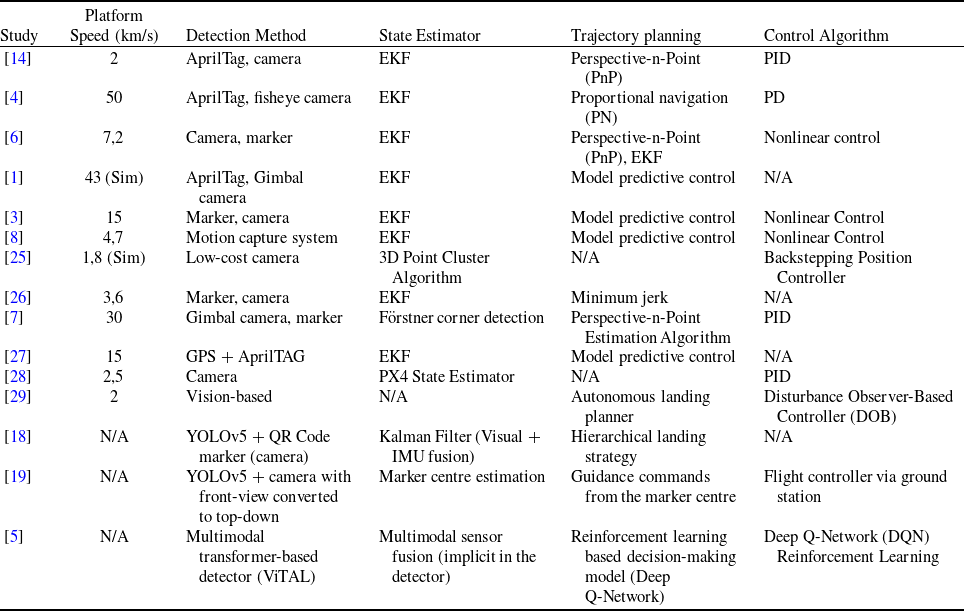
Overall, the literature indicates a clear trend toward hybrid approaches integrating visual perception, inertial sensing, robust control and machine learning to improve UAV landing accuracy and reliability. Despite significant progress, challenges remain particularly in ensuring generalisation across environments, enabling night-time operation, supporting long-range detection and meeting onboard computational constraints. Addressing these gaps, the present study employs GPS data from both the UAV and the moving platform to eliminate range limitations and enable dynamic trajectory updates based on the platform’s direction and speed. The system enhances flight endurance and mission efficiency by adopting a minimum energy consumption strategy. This work contributes to the field by expanding the applicability of autonomous landings in industrial and commercial contexts and offers a comprehensive comparison of existing methods in terms of platform speed, detection, state estimation, trajectory planning and control, as summarised in Table 1.
Methods used in existing studies

3.0 Methodology
This section details the development phases of the autonomous quadrotor landing system and the corresponding methodologies implemented throughout the process.
3.1 Operation procedures
For the autonomous landing of a quadrotor UAV on a moving platform, a system is designed to establish communication with the platform, acquire its position data, estimate its velocity and heading, track its movement and enable a safe landing. The autonomous landing process is structured into the following four stages:
UAV Position Detection: Determining the UAV’s position on the Earth’s surface using Global Positioning System (GPS) data.
Landing Platform Position Detection: This stage involves identifying the position of the landing platform using the same or complementary methods as the previous stage.
Rendezvous Trajectory Generation: Calculating a rendezvous point based on the relative speed, heading and distance between the UAV and the moving platform; generating a trajectory to this point while continuously tracking the platform’s motion.
Precision Landing: Executing a vision-based landing procedure using image markers to guide the UAV precisely onto the moving platform.
3.2 System design
Designing an autonomous landing system for UAVs on moving platforms requires careful consideration of multiple factors identified in the literature. Researchers often employ visual markers and onboard cameras to determine the landing position in GPS-denied environments. When GPS is available, an integrated approach is commonly adopted, combining inertial measurement unit (IMU), GPS, cameras and visual markers. In this study, the UAV and the moving platform utilise GPS and IMU data to enhance navigation and extend operational range. An H-shaped visual marker is placed on the platform for precise landing, and a downward-facing camera is mounted on the UAV.
The proposed system architecture consists of two primary components: a flight control board and an onboard computer. Together, these elements coordinate the UAV’s autonomous landing on a moving platform. The flight control board includes a position estimator that fuses data from the UAV’s GPS and IMU sensors to determine its real-time position. This information and image data from the onboard camera detecting the H marker are transmitted via a cable interface to the onboard computer.
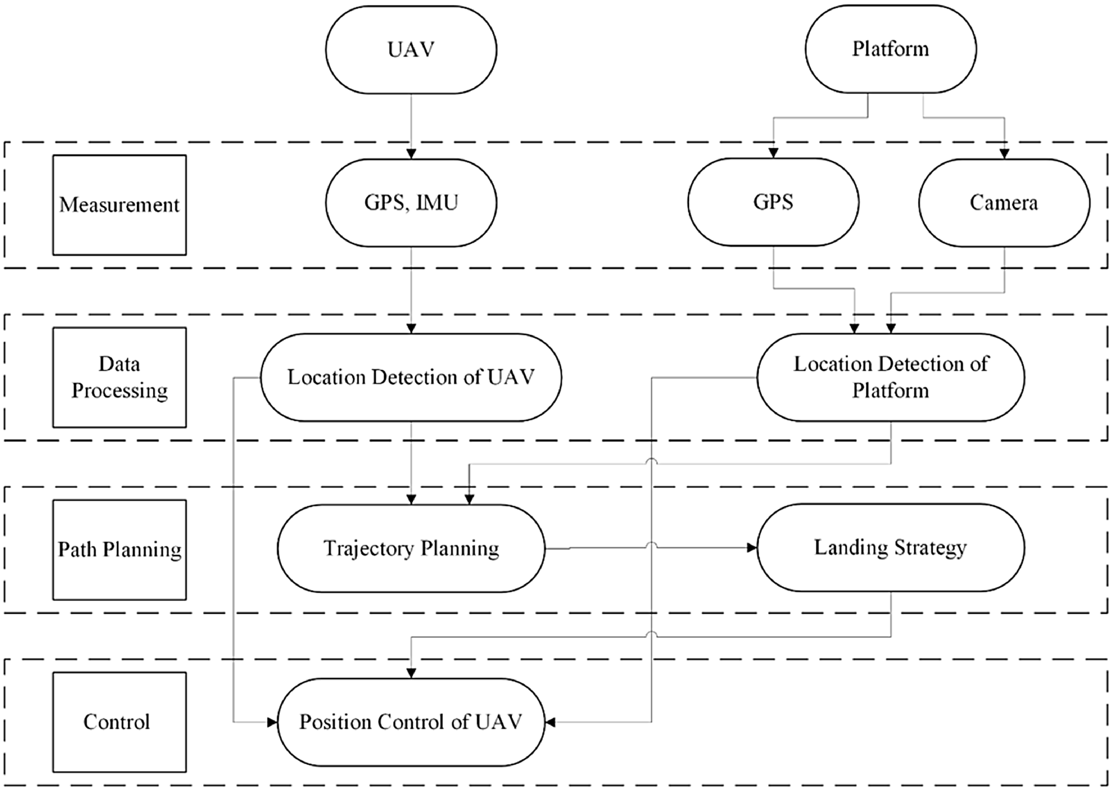
The motor controller on the flight control board regulates the UAV’s motors to either maintain a stable position or follow a predefined trajectory. The onboard computer integrates positional and orientation data from both the UAV and the moving platform to generate a dynamic trajectory for the landing phase. When the H marker is detected, its position is computed and fused with existing data to refine the landing trajectory. A velocity controller then computes the appropriate speed based on the distance to the rendezvous point. This speed command is relayed to the motor controller to guide the UAV through a controlled landing sequence. The overall system design is illustrated in Figure 1.
Autonomous system design for landing a UAV on a moving platform.

The algorithm determines a meeting point using the UAV and ground vehicle positions. If marker data is available, a Kalman filter refines the estimate. When the UAV is within 20 m, it begins descending. If not, it requires position data. Without marker detection, the UAV ascends until the marker is found. Once detected within tolerance, it proceeds to land; otherwise, the process repeats to ensure a safe and accurate landing (see Appendix).
3.3 System architecture
The developed autonomous landing system is structured into four main layers: Measurement, Data Processing, Path Planning, and Control. Unlike traditional methods that rely on cameras, visual markers or motion capture systems – thus limiting UAV operations to short-range and indoor environments due to the absence of GPS integration – the proposed system employs GPS data from both the UAV and the moving platform. This integration significantly extends the operational range and enables outdoor, real-time autonomous landings on moving platforms.
Each layer is designed to perform specific functions that contribute to the landing system’s overall precision and efficiency. The architecture leverages real-time localisation, dynamic trajectory planning and continuous feedback control to achieve reliable performance even under non-ideal conditions (see Fig. 2).
The developed system architecture and its layers.

3.3.1 Measurement layer
In the measurement layer, GPS and IMU data from both the UAV and the moving platform are collected and transmitted to the UAV via wireless telemetry. This real-time data exchange forms the basis for precise localisation and dynamic coordination. The quality of communication is influenced by the selected frequency band and environmental conditions, such as obstacles or interference.
An onboard downward-facing camera is employed to support the final approach and touchdown phase. This visual aid enhances landing accuracy by compensating for potential errors in GPS-based positioning, especially during the last few meters of descent.
The collected data are then processed in the next layer to estimate inter-vehicle distance, identify the landing strip, and determine both vehicles’ relative positions and velocities. These estimations are critical for generating safe and energy-efficient approach trajectories in the subsequent planning layer.
3.3.2 Data processing layer
This layer processes positional data from the measurement layer to determine the UAV and ground vehicle locations for trajectory planning. It calculates the distance between vehicles and detects landing strips from camera images.
Conversion from Geographic to Local Coordinate Systems
Positional data from sensors – latitude, longitude, altitude – are transformed for effective processing. These values are based on the WGS-84 ellipsoid standard in GPS and global navigation systems [Reference Oktal and Yaman30]. The data are converted from geographic coordinates to the Earth-centred, Earth-fixed (ECEF) system, which uses Earth’s centre as the origin. This transformation simplifies quaternion orientation data into three-dimensional Euler angles, making it more practical for further processing and integration into various systems.
N: Radius of Curvature at a Specific Latitude
a: Semi-Major Axis of the Ellipsoid (6378137.0 m)
f: Flattening of the Ellipsoid (1/298.257223563)
e 2: Square of the Eccentricity of the Ellipsoid (f * (2 − f))
 $\phi$
: Latitude in Radians
 $\lambda$
: Longitude in Radians
h: Height in Meters
 \begin{align}N = \frac{a}{{\sqrt {1 - {e^2}{\rm{si}}{{\rm{n}}^2}\left( \phi \right)} }}\end{align}
 \begin{align}X = \left( {N + h} \right){\rm{cos}}\left( \phi \right){\rm{cos}}\left( \lambda \right)\end{align}
 \begin{align}Y = \left( {N + h} \right){\rm{cos}}\left( \phi \right){\rm{sin}}\left( \lambda \right)\end{align}
 \begin{align}Z = \left[ {\left( {1 - {e^2}} \right)N + h} \right]{\rm{sin}}\left( \phi \right)\end{align}
ECEF coordinates are converted into the East-North-Up (ENU) system for local applications. ENU defines local directions – east, north and up – relative to a reference point. A transformation matrix facilitates this, allowing ECEF data to be locally analysed
 $({X_{{\rm{ref}}}},{Y_{{\rm{ref}}}},{Z_{{\rm{ref}}}})$
. Equations (5), (6) and (7) provide the necessary calculations for this conversion, ensuring precise data application across systems.
 \begin{align}{\rm{\Delta }}X = X - {X_{{\rm{ref\;}}}}\end{align}
 \begin{align}{\rm{\Delta }}Y = Y - {Y_{{\rm{ref\;}}}}\end{align}
 \begin{align}{\rm{\Delta }}Z = Z - {Z_{{\rm{ref\;}}}}\end{align}
The transformation matrix (T) for converting ECEF coordinates to ENU coordinates is provided in Equation (8).
 \begin{align}T = \left[ {\begin{array}{*{20}{c}}{ - {\rm{sin}}\left( {{\lambda _{{\rm{ref\;}}}}} \right)}&{{\rm{cos}}\left( {{\lambda _{{\rm{ref\;}}}}} \right)}&0\\{ - {\rm{sin}}\left( {{\phi _{{\rm{ref\;}}}}} \right){\rm{cos}}\left( {{\lambda _{{\rm{ref\;}}}}} \right)}&{ - {\rm{sin}}\left( {{\phi _{{\rm{ref\;}}}}} \right){\rm{sin}}\left( {{\lambda _{{\rm{ref\;}}}}} \right)}&{{\rm{cos}}\left( {{\phi _{{\rm{ref\;}}}}} \right)}\\{{\rm{cos}}\left( {{\phi _{{\rm{ref\;}}}}} \right){\rm{cos}}\left( {{\lambda _{{\rm{ref\;}}}}} \right)}&{{\rm{cos}}\left( {{\phi _{{\rm{ref\;}}}}} \right){\rm{sin}}\left( {{\lambda _{{\rm{ref\;}}}}} \right)}&{{\rm{sin}}\left( {{\phi _{{\rm{ref\;}}}}} \right)}\end{array}} \right]\end{align}
ENU coordinates are calculated by multiplying the transformation matrix by the difference matrices (Equation 9).
 \begin{align}{{\rm{p}}_{{\rm{enu\;}}}} = T \cdot \left[ {\begin{array}{*{20}{l}}{{\rm{\Delta }}X}\\{{\rm{\Delta }}Y}\\{{\rm{\Delta }}Z}\end{array}} \right]\end{align}
Euler angles and position data for each vehicle are utilised to compute yaw angles, which are essential for analysing orientation and motion performance. Yaw angles indicate deviations from a reference point or target, supporting accurate trajectory and orientation control. Additionally, position data enables precise distance calculations between vehicles, facilitating coordinated movement. Consequently, yaw angles enhance both navigational accuracy and operational efficiency, allowing vehicles to complete their tasks synchronised and effectively.
Calculating the distance between vehicles from location data
In aerospace and robotics applications, distances between two points are commonly calculated using metrics such as Euclidean, Manhattan, Minkowski and Hamming, with the choice depending on data dimensionality and application context. Euclidean distance, favoured for its simplicity and intuitive geometric interpretation, is particularly suitable for low-dimensional data [Reference Amato, Bayazit, Dale, Jones and Vallejo31]. This study uses Euclidean distance to compute inter-vehicle distances in aviation scenarios by applying the Pythagorean theorem in Cartesian coordinates, as shown in Equation (10). This approach ensures precise navigation and accurate vehicle coordination.
 \begin{align}D\left( {x,y} \right) = \sqrt {{\mathop \sum \limits_{i = 1}^n {{( {{x_i} - {y_i}} )}^2}} )} \end{align}
Given the minimal impact of UAV altitude on distances, calculations have excluded the Z component, adapting Equation (10) to a two-dimensional format as Equation (11) for horizontal distance measurements.
 \begin{align}{d_{UAV - GV}} = \sqrt {{{\left( {{X_{UAV}} - {X_{GV}}} \right)}^2} + {{\left( {{Y_{UAV}} - {Y_{GV}}} \right)}^2}} \end{align}
Detection of the landing platform and obtaining location information
Visual object detection is widely used to identify and localise objects within images. This study employs the You Only Look Once (YOLO) algorithm, known for its efficient, real-time detection by processing images in a single forward pass. YOLO divides the image into grids and predicts multiple bounding boxes and class probabilities per cell, making it popular in surveillance and autonomous driving applications.
The latest YOLOv8 version [32] was used to detect the landing platform. A simulated dataset of 400 images, featuring variations in UAV altitude, marker positions and occlusions, was created – 360 for training and 40 for validation. The trained model achieved excellent results: mAP@0.5 of 0.995, precision 0.99811, recall 1.0 and F1 score 0.99.
For real-time integration, the ultralytics_ros package [Reference Mori33] processed robot operating system (ROS) image messages, publishing detection results on the /yolo_image topic (see Fig. 3).
Detected marker.

The centre coordinates of the detected object are published on the /yolo_result topic. The input image has a resolution of 640×480 pixels, with the camera’s focal point at (320, 240). For precise landing, the UAV calculates the offset between the detected marker centre and the focal point by subtracting (320, 240) from the detected coordinates. This offset represents the marker’s relative position to the UAV and is critical for accurate localisation and targeted landing.
 \begin{align}x' = \left( {x - 320} \right)\end{align}
 \begin{align}y' = \left( {y - 240} \right)\end{align}
Altitude affects UAV object detection by changing the camera’s field of view, causing pixel measurements to correspond to varying ground areas. Consequently, marker offsets in pixels differ with altitude. To compensate, an altitude-inverse scaling factor converts YOLO-derived pixel coordinates into accurate real-world UAV-relative positions, ensuring precise localisation and navigation.
 \begin{align}x' = \left( {x - 320} \right){\rm{\;}}x\;{\rm{scaleFactor}}\end{align}
 \begin{align}y' = \left( {y - 240} \right)x\;{\rm{scaleFactor}}\end{align}
Measurements were taken at UAV altitudes of 2, 3, 4, and 5 m to calculate the scaling factor. The marker was fixed at coordinates (1,1), with the UAV positioned at (0,0) facing the positive X-axis. The simulation ground, shown in Figure 4, is marked with red, green and blue lines representing the X, Y, and Z axes, respectively, with each grid line indicating 1 m.
At an altitude of 2 m, the detected centre of the marker on the image was at coordinates (119, 45.6). Given the marker’s actual position at (1, 1), the scaling factor was calculated as 0.005 using Equation (17) or (18). This process was repeated for altitudes of 3, 4, and 5 m, with the results summarised in Table 2. It is important to note that, due to the simulation environment, the UAV’s orientation – and thus the camera’s – may not always align with the local coordinate frame, requiring a coordinate transformation matrix to adjust the results accordingly.
Marker coordinates and scaling factors on the image according to UAV altitude

A measurement environment was created to calculate the scaling factor.

These measurements’ scaling factor values of 0.005, 0.010, 0.015 and 0.020 were obtained sequentially. These four data points were used to develop a linear regression model that describes the relationship between UAV altitude (independent variable) and scaling factor (dependent variable). The model consists of an intercept and a slope coefficient multiplied by altitude. Using Equation (16), scaling factor values can be interpolated for intermediate altitudes beyond the measured points. The constants k and m in the Equation are calculated from two known altitude-scaling factor pairs.
 \begin{align}scaleFactor = \;k\; - \;m\;x\;altitude\end{align}
 \begin{align}k = \frac{{\mathop \sum \nolimits_{i = 0}^n (altitud{e_i}scaleFacto{r_i})}}{n}\end{align}
k: Initial scaling factor
m: Slope coefficient expressing the proportional decrease between the height of the UAV and the scaling factor
altitude: The altitude of the UAV.
Because the global position of the detected marker point is unknown at varying altitudes, a coordinate frame transformation is required to express the marker’s position relative to the UAV. This transformation accounts for the camera’s position relative to the UAV and the UAV’s position on the map. The transformation matrix translates the marker coordinates detected by the camera into the UAV’s coordinate system.
Typically, this transformation involves a rotation matrix that aligns the camera’s local coordinate system with the UAV’s. This step is essential since the camera axes may not be directly aligned with the UAV axes, and maintaining correct orientation is critical. The marker’s position, initially represented in the camera coordinate system as (x camera, y camera), is converted into the UAV coordinate system via this rotation matrix.
Equation (18) shows the rotation matrix R(θ), which rotates a vector counterclockwise by an angle θ. This matrix is adjusted based on the camera’s mounting angle relative to the UAV, ensuring that the images captured are accurately integrated into the UAV’s frame, thereby enabling precise navigation and control.
 \begin{align}R\left( \theta \right) = \left[ {\begin{array}{*{20}{c}}{{\rm{cos}}\left( \theta \right)}&{ - {\rm{sin}}\left( \theta \right)}\\{{\rm{sin}}\left( \theta \right)}&{{\rm{cos}}\left( \theta \right)}\end{array}} \right]\end{align}
The position vector of an object detected by the camera is given in Equation (19).
 \begin{align}{p_{{\rm{camera\;}}}} = \left[ {\begin{array}{*{20}{l}}{{x_{{\rm{camera\;}}}}}\\{{y_{{\rm{camera\;}}}}}\end{array}} \right]\end{align}
The camera uses the transformation matrix to transform the position in its coordinate system to the coordinate system of the UAV (Equation 20).
 \begin{align}{p_{{\rm{UAV}}}} = R\left( \theta \right) \cdot {p_{{\rm{camera\;}}}}\end{align}
To quantify the marker’s positional error detected by the camera, the root mean square error (RMSE) method is used. RMSE calculates the square root of the average squared deviations between actual and estimated coordinates. This statistical metric combines errors in X and Y directions into a single value representing the overall location error magnitude. Equation (21) formulates the unified error vector by aggregating deviations from both axes, facilitating clearer error analysis.
In these equations,
 ${x_i},{y_i}$
denote the actual coordinates, while
 $x_i^{\prime},y_i^{\prime}$
represent the estimated coordinates. Equation (22) calculates the mean squared error (MSE), and Equation (23) computes the RMSE.
 \begin{align}{e_{xy,i}} = \sqrt {{{\left( {x_i^{\prime} - {x_i}} \right)}^2} + {{\left( {y_i^{\prime} - {y_i}} \right)}^2}} \end{align}
 \begin{align}{\rm{MS}}{{\rm{E}}_{xy}} = {1 \over n}\mathop \sum \limits_{i = 1}^n e_{xy,i}^2\end{align}
 \begin{align}{\rm{RMS}}{{\rm{E}}_{xy}} = \sqrt {{\rm{MS}}{{\rm{E}}_{xy}}} \end{align}
3.3.3 Path planning layer
The path planning layer has two phases: alignment and approach. In alignment, the UAV updates its position using Kalman filters with an inertial measurement unit (IMU) and GPS data to follow a safe path. During approach, it adjusts altitude and speed to match the moving platform, tracking markers for precise navigation. The UAV descends when within 20 m of the platform; otherwise, it repositions or gains altitude to locate the marker, ensuring a safe landing.
Trajectory planning using a Kalman filter
Trajectory planning for UAV landings on moving platforms integrates algorithms, filtering techniques and machine learning to accommodate target behaviour, environmental conditions, sensor data and system constraints. This approach combines model-based predictions – using kinematic and dynamic models – with sensor-based predictions relying on real-time inputs from cameras or LiDAR, enabling precise manoeuvers in dynamic environments.
The Kalman filter plays a central role by filtering noisy measurements and continuously updating estimates of the target’s position and velocity for real-time trajectory corrections. As a recursive linear estimator, it operates through:
Prediction phase: Estimating future states using system models and control inputs (Equation 24), updating state covariance with process noise (Equation 25).
Measurement prediction: Projecting predicted states into observation space (Equation 26).
Innovation calculation: Computing prediction error (Equation 27) and covariance (Equation 28).
Update phase: Calculating Kalman gain (Equation 29) to balance predicted and observed states, updating the state estimate (Equation 30), and refining covariance (Equation 31).
These recursive steps ensure robust and accurate trajectory planning and target tracking, which are critical for UAV autonomous landings in aerospace applications.
 \begin{align}{x_k} = F \cdot {x_{k - 1}} + B \cdot {u_k} + {w_k}\end{align}
 \begin{align}{P_k} = F \cdot {P_{k - 1}} \cdot {F^T} + Q\end{align}
 \begin{align}\grave{z}_{k} = H \cdot {x_k}\end{align}
 \begin{align}{y_k} = {z_k} - {\hat z_k}\end{align}
 \begin{align}{S_k} = H \cdot {P_k} \cdot {H^T} + R\end{align}
 \begin{align}{K_k} = {P_k} \cdot {H^T} \cdot S_k^{ - 1}\end{align}
 \begin{align}{x_k} = {x_k} + {K_k} \cdot {y_k}\end{align}
 \begin{align}{P_k} = \left( {I - {K_k} \cdot H} \right) \cdot {P_k}\end{align}
 ${x_k}$
: State vector, the state vector at time k represents the predicted state.
 $F$
: State transition matrix, used to predict the next state from the current state.
 ${x_{k - 1}}$
: Actual state at time k − 1.
 $B$
: Control input matrix, used to model external control inputs.
 ${u_k}$
: Control input at time k.
 ${w_k}$
: Continuous process error, a continuous random variable with continuous Gaussian distribution.
 ${P_k}$
: State covariance matrix at time k, represents the uncertainty of the prediction.
 $Q$
: Continuous process error covariance matrix.
 $\grave{z}_{k}$
: Prediction of the measurement at time k.
H: Observation matrix, describes the transformation from the state vector to the measurement vector.
 $R$
: Measurement noise covariance matrix.
I: Identity matrix.
The six-dimensional state vector consists of the UAV’s position (x, y, z), the ground vehicle’s position (x, y) and its yaw angle. In contrast, the two-dimensional observation vector includes the vehicle’s x and y coordinates. The state transition matrix predicts future states based on position changes over time, and the observation matrix relates measurements to the state. The computation error covariance matrix reflects estimation uncertainty, initially set high, while the observation error covariance matrix represents measurement accuracy. These components improve prediction accuracy and support effective UAV–ground vehicle coordination.
Adjusting target orientation to track GV location
In UAV-based ground-vehicle (GV) tracking, determining the UAV’s desired orientation requires computing the angular displacement between the UAV and the GV. Specifically, the desired yaw angle
 $ \varPsi $
desired
defines the heading the UAV must adopt to face the GV’s current position. This angle is calculated using the relative positions of the UAV and GV through the arctangent function, as given in Equation (32):
 \begin{align}{\psi _{{\rm{desired}}}} = {\rm{arctan}}\left( {\frac{{{y_{GV}} - {y_{UAV}}}}{{{x_{GV}} - {x_{UAV}}}}} \right)\end{align}
 ${x_{GV}}$
,
 ${y_{GV}}$
: The x and y coordinates of the ground vehicle
 ${x_{{\rm{UAV}}}},{y_{{\rm{UAV}}}}$
: The x and y coordinates of the UAV
 ${\psi _{{\rm{desired}}}}$
: Shows the target orientation angle.
Equation (33) converts the orientation angle to quaternion form. This transformation ensures that the UAV is correctly oriented towards the target angle.
 \begin{align} q_{\rm{desired}} = {\rm{arctan}}\left( {{\rm{sin}}\left( {\frac{{{\psi _{{\rm{desired}}}}}}{2}} \right),{\rm{cos}}\left( {\frac{{{\psi _{{\rm{desired}}}}}}{2}} \right)} \right)\end{align}
3.3.4 Control layer
The control layer ensures that UAVs and GVs follow planned trajectories by continuously monitoring and adjusting their positions, speeds and directions to enable accurate and synchronised rendezvous. Sensor data, transmitted via wireless telemetry, supports real-time control processes through algorithms such as feedback control, model-based control, fuzzy logic and neural networks. This study employs a proportional-integral-derivative (PID) controller to enhance energy efficiency and performance. It generates control signals based on the error between the desired and current states, using three adjustable gains: proportional (
 ${k_p}$
), which accelerates response but may leave steady-state error; derivative (
 ${k_d}$
), which stabilises output by reacting to the error rate; and integral (
 ${k_i}$
), which eliminates persistent errors by considering their accumulation over time. These components (Equation 34) enable precise and reliable coordination between UAVs and ground vehicles along designated paths.
 \begin{align}u(t) = {k_p} \cdot e(t) + {k_i} \cdot \int_0^t e(\tau)d\tau + {k_d} \cdot {{de(t)} \over {dt}}\end{align}
In this Equation:
 $u(t)$
: Control signal
 $e(t) = r(t) - y(t)$
: Error signal (difference between target value
 $r(t)$
and current value
 $y(t)$
 $\int _0^t e(\tau)d\tau $
: Error accumulation
 $\frac{{\left( t \right)}}{{dt}}$
: Error change rate
The implementation of PID controller involves four main steps: calculating the error between the desired setpoint and the current state; computing the integral of this error to address persistent deviations; determining the derivative to anticipate changes and reduce oscillations; and finally, generating the control signal by combining these components, each scaled by their respective gains (
 ${k_p},{k_i},{k_d}$
). This process enables precise and stable trajectory control, improving the performance of UAV and ground vehicle operations.
 \begin{align}e(t) = r(t) - y(t)\end{align}
 \begin{align}I(t) = I(t-1) + e(t) \cdot {\rm{\Delta }}t\end{align}
 \begin{align}D(t) = \frac{{e(t) - e(t-1)}}{{{\rm{\Delta }}t}}\end{align}
 \begin{align}u(t) = {k_p} \cdot e(t) + {k_i} \cdot I(t) + {k_d} \cdot D(t)\end{align}
The PID controller algorithmically adjusts systems to reach setpoints by iteratively calculating error, integral and derivative terms, updating the control signal to maintain stability, which is crucial for precision in UAV and ground vehicle control systems.
The PID controller calculates the error between current and target positions to determine velocity commands (
 ${v_x}$
,
 ${v_y}$
), guiding the UAV towards the target. Equation (39) applies
 ${v_x}$
along the x-axis, considering the UAV’s orientation.
 \begin{align}x_{{\rm{UAV\_trt}}} = {x_{{\rm{UAV\_curr}}}} + \left( {{\rm{cos}}\left( {{\rm{UAV\_yaw}}} \right) \cdot {v_x} - {\rm{sin}}\left( {{\rm{UAV\_yaw}}} \right) \cdot {v_y}} \right)\end{align}
 \begin{align}{y_{{\rm{UAV\_trt}}}} = {y_{{\rm{UAV\_curr}}}} + \left( {{\rm{sin}}\left( {{\rm{UAV\_yaw}}} \right) \cdot {v_x} + {\rm{cos}}\left( {{\rm{UAV\_yaw}}} \right) \cdot {v_y}} \right)\end{align}
This formula converts the velocity command
 ${v_y}$
into x and y components based on the UAV’s yaw angle, ensuring accurate and stable movement toward the target position.
3.3.5 Simulation environment and communication
The simulation environment, built on Ubuntu 20.04, integrates ROS, Gazebo, PX4 flight control board, and QGroundControl. The IRIS quadrotor UAV and Ackerman ground vehicle models from the Gazebo library were utilised. The IRIS UAV [2], designed for aerial imaging, supports autonomous takeoff, landing and GPS-based missions via PX4, measuring 550 mm in length, 100 mm in height, weighing 1582 g with battery, with a flight time of 10–15 minutes and payload capacity up to 425 g. Effective communication between Gazebo, PX4, QGroundControl and the UAV–UGV system is essential for precise autonomous landing. ROS manages telemetry simulation between UAV and UGV within Gazebo, interfaces with PX4 through MAVLink, and enables real-time sensor data and command exchange. PX4 processes sensor inputs for flight control and relays data to QGroundControl for live monitoring. The ground vehicle also operates via a ROS-based system, facilitating coordinated interactions within the simulation environment.
4.0 Simulation scenarios
This section presents a two-phase analysis to evaluate the proposed autonomous landing method’s performance and robustness. The first phase compares the new method with traditional landing techniques to assess its effectiveness. In the second phase, three simulation scenarios are designed to test the UAV’s performance under varying environmental and operational conditions, such as wind and fog, thereby examining the system’s adaptability and resilience in realistic settings.
The first part analyses autonomous landing on a ground vehicle moving in a straight line, focusing on the UAV’s ability to follow the vehicle, detect the landing strip and perform accurate trajectory planning and tracking. In the second part, the developed system is compared to traditional methods using metrics including energy consumption, trajectory duration, landing phase times, total mission time and distance covered.
Scenario 1: This scenario evaluates the UAV’s adaptability in following a ground vehicle executing a 90-degree turn. It focuses on how effectively the trajectory planning algorithm allows the UAV to maintain accurate tracking and adapt to sudden changes in the path, demonstrating system stability and flexibility.
Scenario 2: Building on Scenario 1, variable wind conditions are introduced to assess the performance of the speed and trajectory controller. This scenario examines the UAV’s ability to maintain stability and complete an autonomous landing under dynamic wind speeds and directions.
Scenario 3: Dense fog is added to Scenario 2 to evaluate the robustness of the landing strip detection method. This test investigates the impact of reduced visibility on marker detection accuracy and the UAV’s capability to perform reliable landings in low-visibility conditions.
Throughout the simulations, the UAV and ground vehicle maintain maximum speeds of 12 m/s (43.2 km/h) and 6.4 m/s (23 km/h), respectively, with control managed via the PIXHAWK flight controller. At an altitude of 20 m, the UAV – initially positioned at (0,0) – can detect markers within a ±20 m range in both axes, achieving an Intersection over Union (IoU) of ∼0.5. As the altitude decreases to 10 m, the detection range narrows to ±10 m, with the IoU improving to 0.75. At 5 m, the range contracts to ±5 m, with IoU reaching 0.8.
These results confirm that detection accuracy improves while the UAV’s field of view narrows at lower altitudes. For instance, at 20 m, a 0.5 m² marker can be detected within a 400 m² area with IoU ≥ 0.5, whereas at 5 m, it can be detected within a 25 m² area with IoU ∼0.9.
To evaluate marker detection accuracy, landing markers were placed at (3,3), (–3,3), (3,–3), and (–3,–3), with the UAV hovering at 5 m. For each marker, 1,000 position estimations were performed under simulated wind, yielding an average RMSE of 0.056, confirming the system’s high precision under environmental disturbances.
4.1 Autonomous landing of UAV
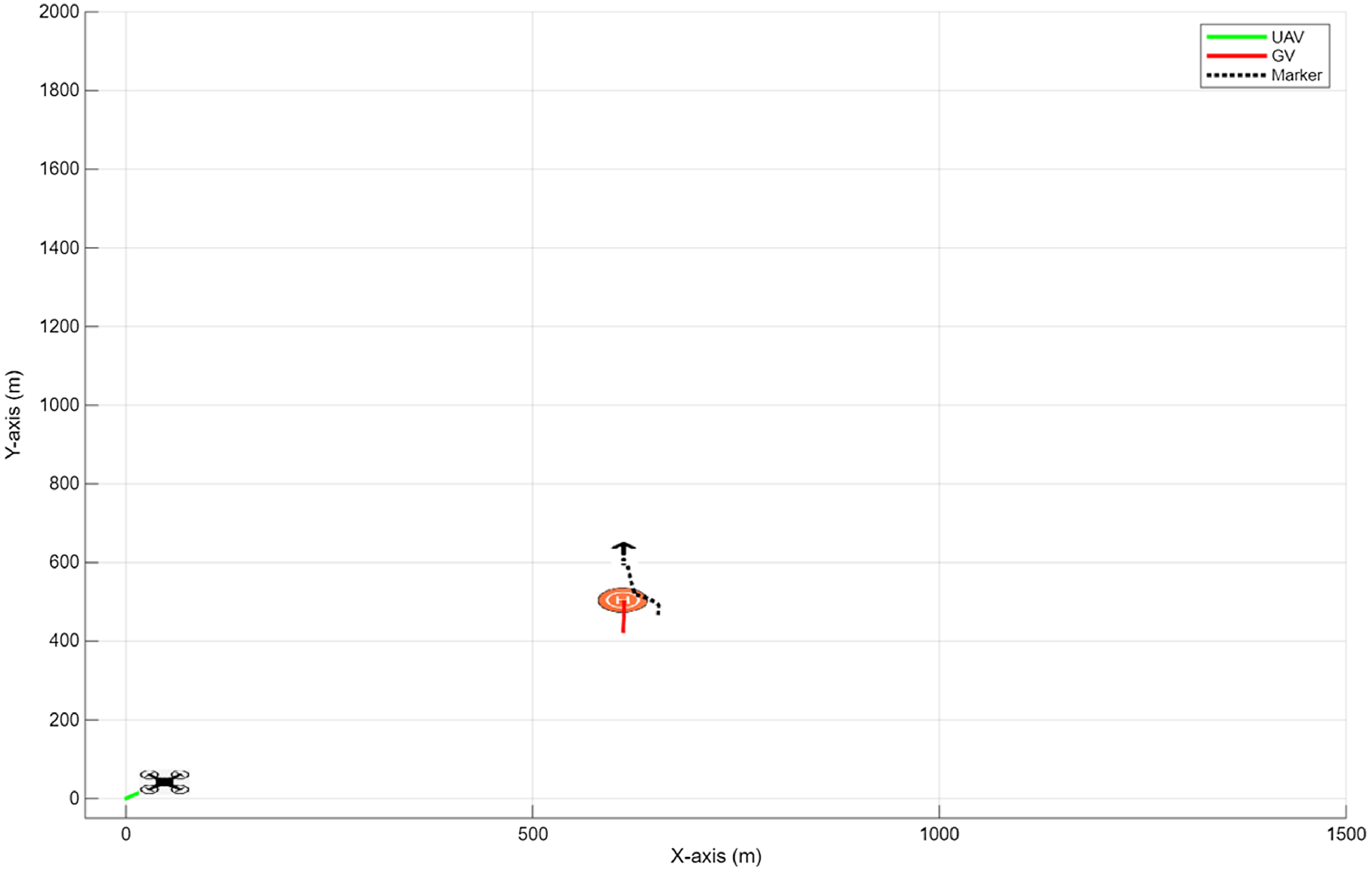
In the simulation environment, the ground vehicle moves at a speed of 6.4 m/s (23 km/h) along the positive Y-axis, starting from the position (646, 724), marked as point H on the graph. Meanwhile, the UAV is positioned at (0,0), hovering at an altitude of 10 m, and indicated as UAV on the graph. The UAV can achieve a maximum speed of 12 m/s (43.2 km/h). The distance between the UAV and the ground vehicle is set at 970 m. Upon initiating the process, trajectory points generated using a Kalman filter begin to appear, shown by a black upward arrow. The first trajectory point generated is (684,772). Due to the lack of positional history for both vehicles, the initial error rate is high, as illustrated in Figure 5.
Representation of the trajectory points generated at the initial time.

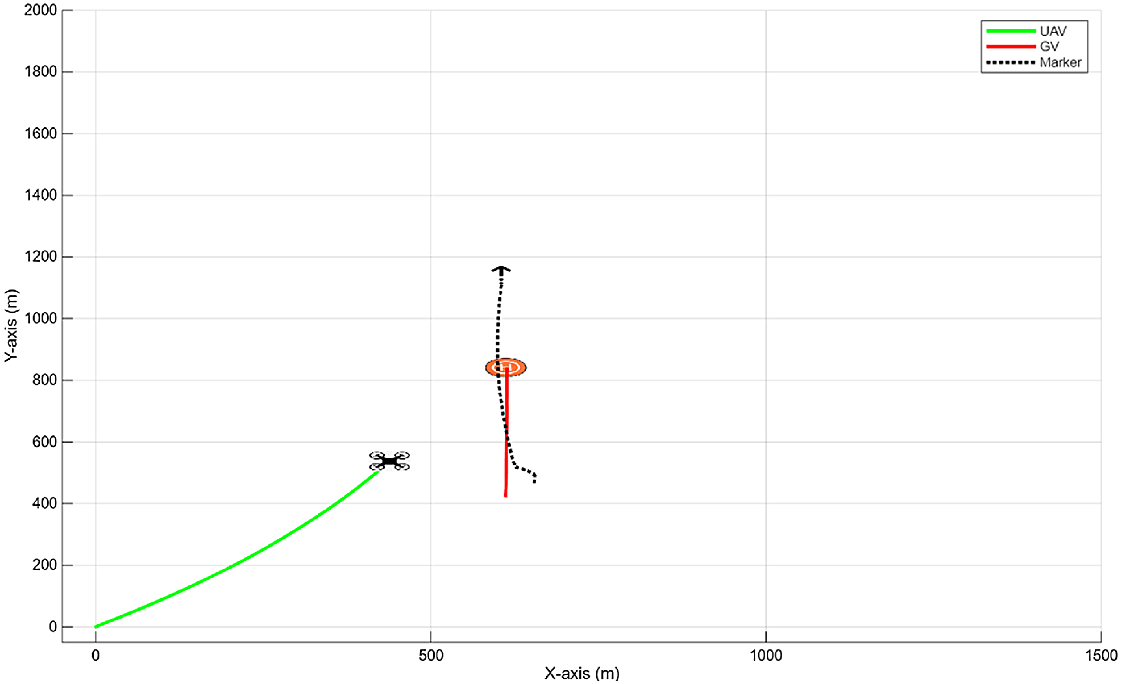
The Kalman filter continuously updates trajectory points, using the direction, speed and position of the ground vehicle and the position of the UAV as a reference. These updates ensure the trajectory aligns with the ground vehicle’s path and potential forward movement, as depicted in Figure 6.
The UAV’s trajectory tracking phase.

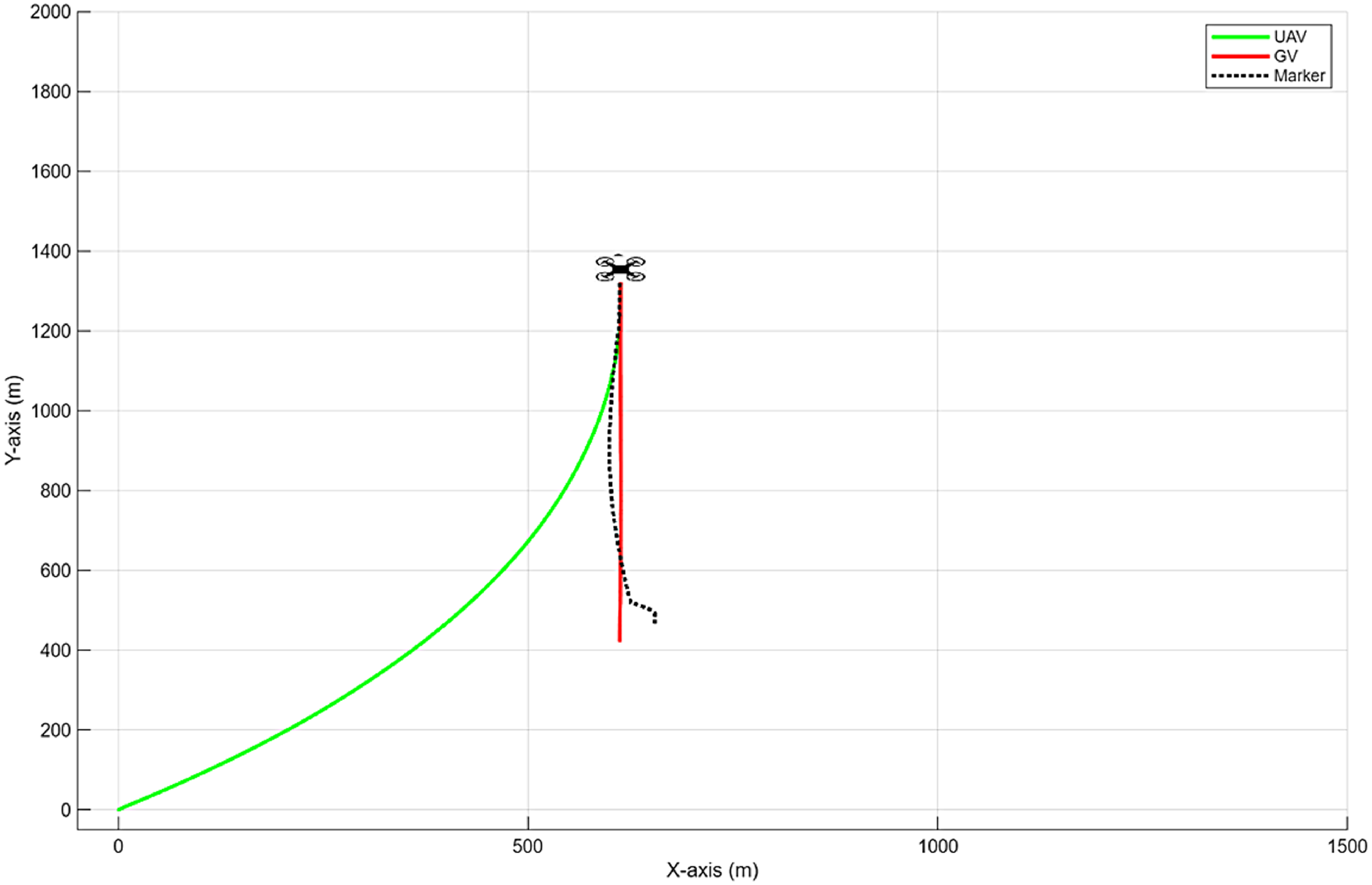
The UAV successfully landed on the ground vehicle after 178 s of flight (Fig. 7).
Completion of autonomous landing.

As illustrated in Figure 8a, the GV maintains a constant speed of 6.4 m/s (23 km/h). When the task begins at the 225th second in the simulation, the UAV accelerates to 11 m/s (40 km/h) to close the gap with the ground vehicle. As the distance decreases, the PID controller reduces the UAV’s speed, matching the speed of the ground vehicle upon landing.
(a) Speed of vehicles. (b) Altitude of UAV.

In Figure 8b, the UAV is limited to a cruising altitude of 10 m in the simulation environment. As it proceeds, the UAV maintains this altitude, gradually decreasing as it approaches the ground vehicle to complete the landing phase. The final altitude of the UAV aligns with the marker’s altitude, which is 1 m.
4.2 Comparison of the traditional method and the developed method
In the traditional method, the UAV targets the position of the ground vehicle and moves directly towards it. When the marker is detected within specific tolerance values via the camera, the UAV reduces altitude to execute the landing. In contrast, the developed method involves creating a rendezvous point along the trajectory of the moving ground vehicle and gradually decreasing altitude for precise landing when the distance between the vehicles is less than 20 m.
The ground vehicle is initially positioned at (646,724) while the UAVs begin at (0,0), separated by 970 m. UAV1, using the traditional method (TM), lands on the ground vehicle at (673,1924). Meanwhile, UAV2, which implements the developed method (DM), flies a total of 1883 m and lands at (672,1770), showing a reduction of 154 m compared to UAV1, as demonstrated in Figure 9.
Autonomous landing of UAVs with the traditional and the developed method.

UAV1 takes 168 s for the trajectory flight to reach the target and initiates landing, while UAV2 accomplishes this in 157 s (Figure 10a). UAV1 completes the autonomous landing in 23 s, whereas UAV2 does so in 11 s (Figure 10b), resulting in a total autonomous landing duration of 191 s for UAV1 and 168 s for UAV2.
(a) Speed of vehicles. (b) Altitude of UAVs.

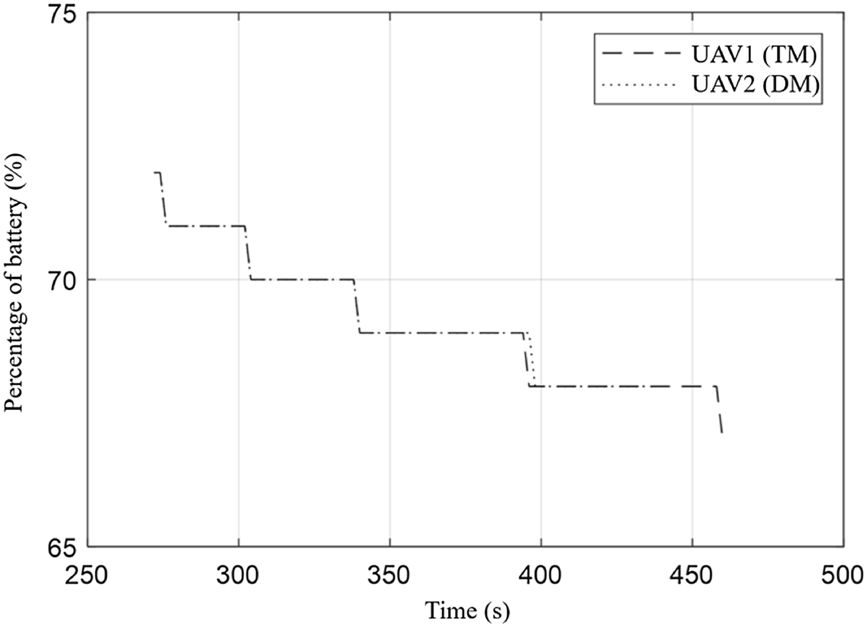
Both UAVs are equipped with 11.1V (3S LiPo) 3500 mA batteries. They commence the autonomous landing phase with 72% battery capacity. UAV1 concludes the operation with 67% battery remaining, while UAV2 finishes with 68% (Fig. 11).
Battery percentages of UAVs during operation.

4.3 Scenario 1 – Autonomous landing of the UAV during the platform’s change of direction
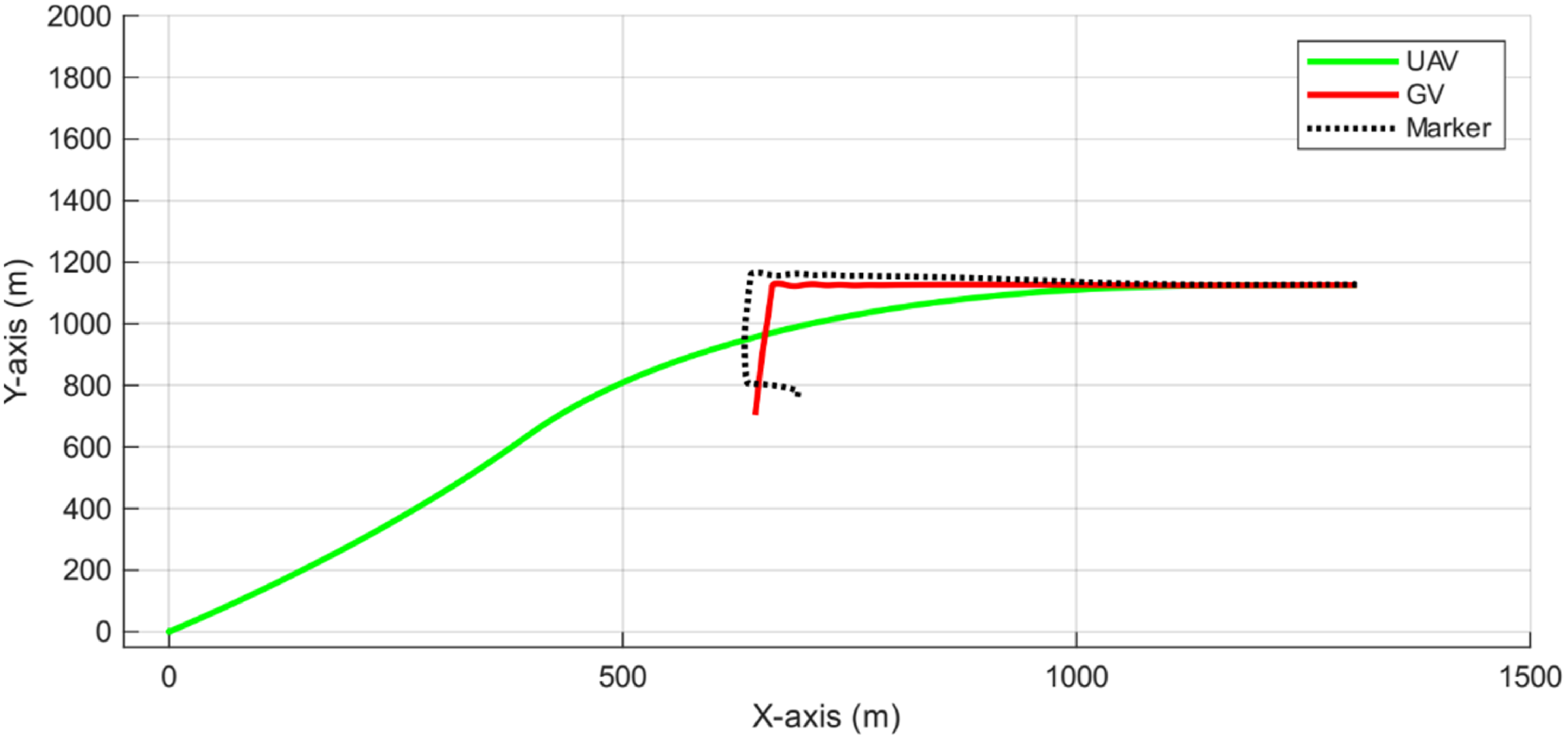
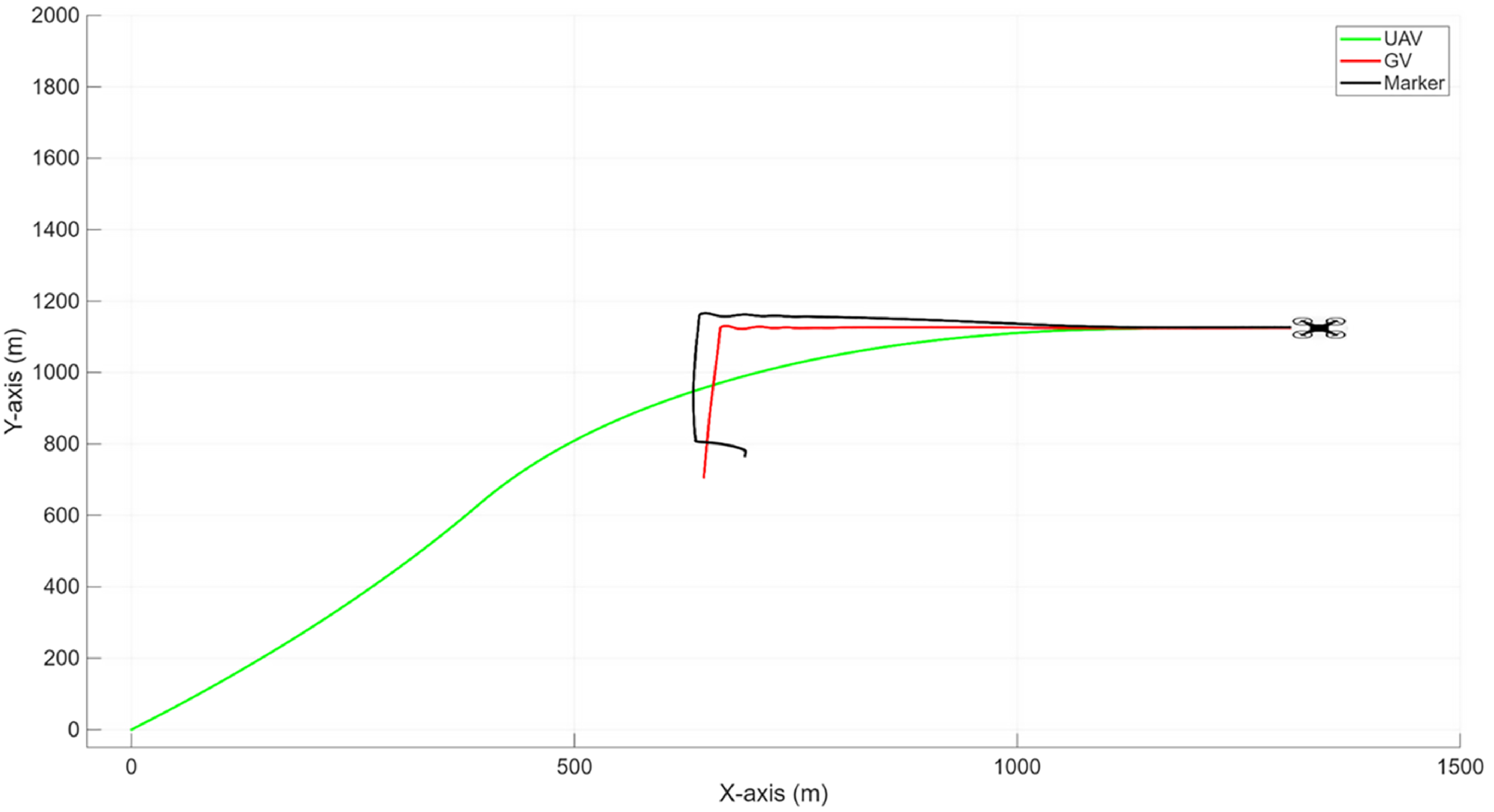
In Scenario 1, the situation considered involves the UAV’s autonomous landing as it moves along its trajectory, while the ground vehicle undergoes a 90° change in direction. At the start of the simulation environment, the ground vehicle is at position (646,724), moving positively along the Y-axis at a speed of 6.4 m/s (23 km/h). The UAV is in standby mode at position (0,0) at an altitude of 10 m, with a maximum speed capability of 12 m/s (43.2 km/h). The initial distance between them is 970 m.
When the ground vehicle reaches position (676,1129) and the UAV is at (369,594), with a separation of 616 m between them, the ground vehicle changes direction by 90° and begins moving positively along the X-axis. As a result of Scenario 1, the UAV successfully executes an autonomous landing following the trajectory depicted in Figure 12. After a 150-s flight, the UAV completes its autonomous landing at the ground vehicle in 385 s.
Scenario 1: Completion of autonomous landing.

As observed in Figure 13a, despite a reduction in speed during the ground vehicle’s change of direction, its speed remained recorded at 6.4 m/s. On the other hand, the UAV maintained a speed up to a maximum of 12 m/s during the approach phase. Subsequently, fluctuations in the UAV’s speed were noted due to the manoeuvers performed.
(a) Scenario 1: Speed of vehicles. (b) Scenario 1: Altitude of UAV.

As depicted in Figure 13b, the UAV maintained an altitude averaging 10 m until the approach phase. During the approach, the altitude gradually decreased, enabling the UAV to land, ultimately reaching the altitude of the marker on the ground vehicle, which remained at 1 m.
4.4 Scenario 2 – Autonomous landing of the UAV under the influence of variable wind direction and speed
In Scenario 2, the operation outlined in Scenario 1 has been modified to incorporate variable wind conditions, with speeds up to a maximum of 6 m/s (21.6 km/h) in varying directions. Initially positioned at (646, 723), the ground vehicle moves along the positive Y-axis at 6.4 m/s (23 km/h). The UAV is positioned at (0,0) at an altitude of 10 m and is in standby mode, with a maximum speed capacity of 12 m/s (43.2 km/h). The effect of wind on the UAV and the wind compensation applied by the UAV are shown in Figure 14. As in the other scenarios, the distance between the UAV and the ground vehicle is 970 m.
Representation of the wind’s effect on the UAV.

As depicted in Figure 15, under these challenging wind conditions, the UAV completed its landing on the moving ground vehicle in 157 s.
Scenario 2: Completion of autonomous landing.

As depicted in Figure 16a, the UAV constantly adjusts its speed to maintain its position on the trajectory against the wind. Figure 16b provides the altitude of the UAV for Scenario 2.
(a) Scenario 2: Speed of vehicles. (b) Scenario 2: Altitude of UAV.

4.5 Scenario 3 – Detection and localisation of the marker in a foggy simulation environment
In this scenario, the operation outlined in Scenario 2 is evaluated with the addition of fog to assess the UAV’s performance. Fog significantly reduces visibility and introduces challenges for detection and sensing systems. This scenario evaluates how effectively the method designed for low visibility conditions can identify the landing strip.
In the simulation environment, the visibility range is limited to a maximum of 7 m, which increases the difficulty due to fog conditions. The UAV begins detecting the marker at an average altitude of 5 m. However, the IoU threshold of 0.5 is surpassed at a 5-m altitude, where the average IoU value recorded is 0.58, and the RMSE is 0.150 (Fig. 17). Under simulation conditions without fog at the same altitude, the IoU value is 0.72, while the RMSE value is 0.066.
Illustrates the image of the ground vehicle detected by the UAV at a 5-m altitude under foggy weather conditions.

As shown in Figure 18, despite these challenging conditions, the UAV executed a landing on the moving platform.
Autonomous landing of the UAV under adverse weather conditions of fog and wind.

At the 733rd second of the simulation, the UAV initiated its flight and successfully landed on the ground vehicle after a flight duration of 160 s. As expected, the UAV continuously adjusted its speed to manage wind conditions (Fig. 19a). The changes in the UAV’s altitude are shown in Figure 19b.
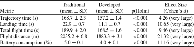
Statistical comparison of performance metrics between the traditional and developed autonomous landing approaches (30 runs, mean ± SD, p-values and effect sizes)

Flight durations obtained in scenarios

(a) Scenario 3: Speed of vehicles. (b) Scenario 3: Altitude of UAV.

4.6 Evaluation of simulation results
To evaluate the performance of the developed autonomous landing system, a comparative statistical analysis was conducted against the traditional approach. All test flights were repeated 30 times in a controlled environment free from wind, fog or external disturbances that could cause trajectory deviations. The evaluation criteria included Trajectory Time (s), Landing Time (s), Total Flight Time (s), Flight Distance (m) and Battery Consumption (%).
The comparative results are presented in Table 3, where values are reported as mean ± standard deviation (SD). In addition to descriptive statistics, Holm-corrected p-values are provided to confirm the statistical significance of the improvements, and Cohen’s d effect sizes quantify the magnitude of the observed differences.
With the proposed method, considering a 970 m distance between the UAV and the ground vehicle, an average UAV speed of 12 m/s, and a ground vehicle speed of 6.4 m/s, the trajectory tracking time before the landing phase was reduced from 23 ± 0.7 s to 11 ± 0.7 s, while the total autonomous landing duration decreased from 190 ± 2.0 s to 168 ± 1.6 s. These improvements represent a 12% reduction in total flight duration, accompanied by significantly shorter landing phases and lower energy consumption. Statistical analysis confirmed that all improvements are highly significant (p < 0.001), with huge effect sizes (Cohen’s d > 4), demonstrating that the developed approach provides both robust and practically meaningful gains compared to the traditional method.
Three scenarios were simulated to evaluate the system’s performance under variable wind and fog conditions, with the total UAV landing durations presented in Table 4. Despite the challenging environmental factors, the flight durations remained equal or lower in certain scenarios due to the manoeuvering of the ground vehicle, which deviated from a linear trajectory along the Y-axis.
In Scenario 1, the UAV performed an autonomous landing while the ground vehicle executed a 90° manoeuver. Following trajectory correction, landing successfully occurred after 150 s of flight. This scenario served as a baseline for Scenario 2 and Scenario 3, where additional environmental factors were incrementally introduced.
In Scenario 2, variable wind conditions increased the approach and landing duration to 157 s. The wind made navigation and platform landing more challenging, extending the flight duration. In Scenario 3, fog conditions further increased the flight duration to 160 s. The presence of fog reduced visibility, making it more difficult for the UAV to detect the landing marker.
Under normal conditions, the UAV detects the platform at an altitude of 10 m. Experiments were conducted with maximum detection ranges of 10 m and 7 m to assess the impact of reduced visibility. At 7 m visibility, the UAV detected the platform at 5 m altitude and successfully landed despite variable wind conditions. However, when the maximum visibility reduced to 5 m, the UAV detected the platform only at 3 m altitude, resulting in an unsuccessful landing attempt.
These results demonstrate the effectiveness of the proposed autonomous landing system under varying environmental conditions and highlight its adaptability to dynamic scenarios.
5.0 Conclusion
This study presents a comprehensive framework for the autonomous landing of rotary-wing UAVs on moving platforms by integrating trajectory-based planning, multi-sensor data fusion and deep learning-based visual detection. The proposed system addresses one of the key challenges in UAV autonomy – accurate and efficient landing on dynamically moving ground vehicles – by leveraging a novel Kalman filter-based trajectory prediction mechanism in conjunction with real-time object recognition through the YOLO v8 model.
Simulation results demonstrate that the system can significantly reduce flight duration and energy consumption while maintaining high landing accuracy. Compared to traditional direct navigation methods, the developed approach reduced the total autonomous landing time by 12% (from 191 s to 168 s), shortened the trajectory by 154 m, and exhibited more efficient battery utilisation. These improvements are achieved through continuous trajectory point updates based on the UAV’s and ground vehicle’s motion parameters, ensuring synchronisation with a predicted rendezvous point rather than the vehicle’s instantaneous location.
Three rigorous simulation scenarios were designed to validate the system’s robustness under real-world environmental complexities:
Scenario 1 involved a sudden 90° directional change in the ground vehicle’s trajectory. The UAV successfully recalibrated its path mid-flight and completed a precise landing after a 150-s flight segment, demonstrating strong adaptability in dynamic environments.
Scenario 2 introduced variable wind conditions up to 6 m/s. Despite external disturbances, the UAV maintained stable control through adaptive velocity adjustments and successfully landed in 157 s, validating the system’s environmental resilience.
Scenario 3 added limited visibility due to simulated fog, reducing the UAV’s visual detection range. Even under these degraded sensing conditions, the system successfully landed in 160 s, with acceptable IoU (0.58) and RMSE (0.150) values for marker localisation. However, the results also indicate a performance threshold, as further reduced visibility (5 m detection range) led to failed landings, emphasising the importance of sensor fusion in adverse conditions.
The findings underscore the effectiveness of combining predictive trajectory planning with perception-aware control for precision landing. Unlike traditional methods that rely solely on instantaneous GPS targeting and final-stage image recognition, the proposed system continuously anticipates the ground vehicle’s future position, generating more efficient 3D descent trajectories that include altitude adaptation.
The proposed system is modular and platform-independent, enabling integration with diverse UAV architectures and ground vehicles. It is particularly well-suited for applications requiring dynamic platform cooperation, such as mobile surveillance, autonomous logistics and emergency response missions.
Future work will focus on real-world flight validation under GPS-denied environments, integration of onboard simultaneous localisation and mapping (SLAM)-based navigation, and reinforcement learning for real-time trajectory adaptation. Moreover, additional robustness enhancements will be explored by fusing radar or thermal sensing for poor-visibility scenarios.
Acknowledgements
This study was supported by the Scientific Research Projects Commission (BAP) of Eskişehir Technical University under project number 22DRP222.
Appendix
Flowchart of the UAV’s landing algorithm on a moving platform