
Introduction
Photocathodic protection (PCP) is an environmentally benign and sustainable corrosion-resistant alternative, with superior photoelectric performance, compared to the traditional sacrificial anode and impressed current cathodic protection.[Reference Sun, Na, Cui, Yuan, Wang, Jian, Jian and Jing1,Reference Li, Wang, Wei and Hou2] Electronic transmission for PCP involves the bulk transfer of photogenerated electrons to the metal substrate coupled with the photoanode film. This reduces the Fermi level of the metal below its standard corrosion redox potential, thus preventing corrosion.[Reference Zhou, Zeng and Zhong3–Reference Liu, Hou, Zhao, Ma and Hou7]
Recent studies on the photoelectrochemical (PEC) performance of TiO2, an abundant and nontoxic photocatalyst, for the PCP of metals suggest that it effectively prolongs the protection time of stainless steel.[Reference Wang, Wei, Zhang, Sun, Li and Zhang8–Reference Hakimizad, Raeissi, Golozar, Lu, Blawert and Zheludkevich10] Due to a large bandgap, TiO2 can only absorb the UV wavelengths of sunlight (~4% of sunlight falls within this range), limiting the effectiveness of protection from TiO2 photoanodes under the sunlight.[Reference Ning, Ge, Wang, Li, Li, Liu and Huang11–Reference Gurusamy, Kulanthaisamy, Hari, Ananthi and Boobalan13] Rapid recombination of the photogenerated electron–hole (e−–h+) pairs[Reference Cao, Nasori, Wang, Wen, Xu, Mi and Lei14] in the TiO2 renders it unable to work effectively in low-light levels as well and therefore, crucial to enhance the visible-light absorption range of TiO2 and store the energy of photogenerated carriers to demonstrate the better protection performance. Prior research has been done on the modification of TiO2 films by building a heterojunction structure to improve the visible-light absorption and separation efficiency of photoinduced holes (h+) and electrons (e−).[Reference Cao, Nasori, Wang, Wen, Xu, Mi and Lei14–Reference Bu and Chen17] Strategies to extend the TiO2 photoabsorption range into the visible region include surface modification using noble metal as a co-catalyst, doping with transition metal and nonmetallic elements, and coupling with narrowband semiconducting quantum dots (SQDs) such as Ag2S,[Reference Liu, Liu, Yang, Ma, Li, Yin, Sato, Sekino and Wang18] CdS (E g = 2.4 eV),[Reference Lin, Lai and Hu16,Reference Li, Lin, Li and Lin19] PbS (E g = 0.3 eV),[Reference Zhang, Xu, Gong, Tao, Sun, Lv, Chen, Jiang, He and Wang20,Reference Etgar, Park, Barolo, Nazeeruddin, Viscardi and Graetzel21] and WO3.[Reference Tatsuma, Takeda, Saitoh, Ohko and Fujishima22] QD nanocrystals inject electrons into the TiO2 nanotube arrays (NTAs) upon excitation via visible light, thereby enabling their use as photosensitive electrodes. This strategy still suffers from the low quantum efficiencies due to either a wide bandgap (CdS E g = 2.4 eV) or the discontinuous band edges of the adjacent layer (PbS).
In this study, we propose to enhance the visible-light absorption and durability of sensitized TiO2 NTA photoelectrodes using low-bandgap lead sulfide (PbS) and cadmium sulfide (CdS) QDs. The cascade structure of CdS/PbS/TiO2 features an arrangement of energy levels between CdS and PbS that form a step-like structure of band gaps. This reduces the energy needed to induce electron separation and hole recovery, thus increasing the number of available photoelectrons. CdS and PbS demonstrate excellent band alignment with TiO2,[Reference Li, Lin, Chen, Zhang, Xing, Chen, Jiao and Mei23–Reference Dong, Wu, Zhang, Lu, Zhang, Wang, Ma and Wang25] thus promoting the light harvesting of the films in the visible region. However, few investigations on the application of CdS/PbS cosensitized TiO2 NTAs films for PCP of metals, have been made so far.
The successive ionic layer absorption and reaction (SILAR) method was used to prepare the heterojunction QDs decorating TiO2 NTA composite films, and the influencing parameters in the preparation of CdS and PbS-sensitized TiO2 NTAs were systematically investigated. The microstructures and chemical structures were then analyzed using a scanning electron microscope (SEM) and x-ray diffraction (XRD) respectively. PCP performance was conducted, in which the 304SS is coupled with the photoanode film in a 3.5% NaCl solution under illumination and dark states. The PCP mechanism for 304SS using the photoanode was discussed. With the cascade structure of PbS/CdS/TiO2 photoanode, more than 3 months of protection on 304SS can be achieved, approaching an unprecedented record in the field.
Experimental
Synthesis of CdS/PbS/TiO2 NTAs composite films
TiO2 NTAs were first prepared by the anodic oxidation method at 20 V for 1 h in a traditional two-electrode electrolytic cell at room temperature. Anodizing electrolytic solution was prepared from 0.1 mol/L H3PO4 + 0.5 wt% NH4F in deionized water. The prepared samples then were annealed for 3 h at 500°C in a muffle furnace.
CdS and PbS SQDs were assembled uniformly onto the TiO2 NTAs by the SILAR method.[Reference Guijarro, Lanavillarreal, Lutz, Haque and Gómez26,Reference Parize, Cossuet, Appert, Chaixpluchery, Roussel, Rapenne and Consonni27] The mixed solution of ethanol and water with the ratio of 4:1 was used as a solvent in order to advance the infiltration of the precursor solution into the TiO2 nanotube by decreasing the surface tension of the electrolyte solution. In the experiments, each immersion lasted for 15 s under the ultrasonic power of 80 W and ultrasound-assisted technology was used to expel air from the inside of nanotubes and make solvents more accessible. The solutions comprising of 0.01 mol/L Cd(NO3)2, 0.01 mol/L Na2S and 0.01 mol/L Pb(NO3)2, 0.01 mol/L Na2S were used as precursor solutions of CdS and PbS respectively. In the preparation of 15CCdS/9CPbS/TiO2, the TiO2 samples were immersed in the solution of 0.01 mol/L Cd(NO3)2 for 15 s, rinsed with a solvent, dried in the ambient air, and then immersed in the 0.01 mol/L Na2S for the formation of cadmium sulfides. After sulfide formation, the electrode was cleared and dried with the same protocol to allow the final formation of the CdS layer. This deposition process was repeated for 15 times. After the deposition of CdS, the cation precursor Cd(NO3)2 was changed to Pb(NO3)2, and the same protocol was used to deposit PbS. The prepared sample was marked as 15CCdS/9CPbS/TiO2. Meanwhile, 15CCdS/TiO2 and 9CPbS/TiO2 were prepared as control samples. The above samples were dried at 80°C in the drying box (DH-201) for 30 min and then heated at 300°C for 2 h with a ramping rate of 2°C/min.
Characterization of chemical composition and morphology
The microstructure of 304SS under long-term PCP was recorded by a metallurgical microscope (Nikon, ECLIPSE, MA200). The microstructure of the photoanode films was observed using an SEM (QUANTA650, FEI). The crystallographic structure of the photoanode films was analyzed by XRD (Rigaku SmartLab, Japan) with Cu Kα radiation.
PEC and PCP tests
The photocurrent response i−t was conducted by an electrochemical workstation (IM6, Germany) in a conventional three-electrode corrosion cell system with the 0.2 mol/L Na2SO3 + 0.1 mol/L Na2S electrolyte solution as the sacrificial electrolyte. The working electrode was a photoanode film (the exposed area was 10 × 10 mm2); the reference electrode and the counter electrode were saturated calomel electrode (SCE) and a platinum gauze, respectively. Xenon lamp was used as the source of simulated sunlight (100 mW/cm2).
In the PCP test system, the solution in the photolysis cell contains 0.1 mol/L Na2SO3 + 0.2 mol/L Na2S, and the corrosion cell contains 3.5% NaCl solution. The two cells were connected by a U-type salt bridge. The working areas of 304SS are same as the photoanode film 10 × 10 mm2. Open circuit potential (OCP), potentiodynamic polarization (PDP), and electrical impedance spectroscopy (EIS) tests were carried out under both illumination and dark conditions. The PDP tests were performed in the range of −500 mV to +1 V relative to OCP. The frequency of EIS tests was in the range of 0.01 Hz–10 kHz with the voltage amplitude of 10 mV.
Results and discussion
Surface characterization of photoanode films
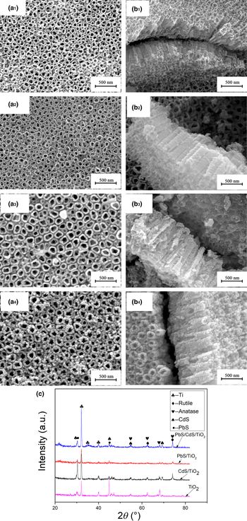
The morphology of the photoanode films was first examined shown in Fig. 1. Highly ordered TiO2 NTAs could be clearly observed with an average inner diameter of ~100 nm, length of ~700 nm, and a wall thickness of ~20 nm, as shown in Figs. 1(a1) and 1(b1). The bottom of the TiO2 NTAs was closed with a uniform compact outline, thus indicating successful preparation of the NTAs. After the deposition of CdS layers, an increase in the wall thickness of the nanotubes was observed, and a large number of CdS SQDs can be seen to uniformly decorate the surface as well as the interior of the 15CCdS/TiO2 NTAs [Figs. 1(a2) and 1(b2)]. Similar phenomena were observed for the deposition of the PbS layer on TiO2 NTAs [Figs. 1(a3) and 1(b3)]. With the further decoration of PbS on 15CCdS/TiO2 NTAs, it can be seen that the wall thickness further enhanced; the NTAs film were uniformly decorated by CdS and PbS QDs, which were found inside and outside of the nanotubes [Figs. 1(a4) and 1(b4)]. These results confirm that a composite heterojunction of TiO2 nanotubes/PbS and CdS layers were successfully deposited in tandem.
SEM images of the photoanode films: (a1) surface image of TiO2 NTAs; (b1) cross-sectional image of TiO2 NTAs; (a2) surface image of 15CCdS/TiO2 NTAs; (b2) cross-sectional image of 15CCdS/TiO2 NTAs; (a3) surface image of 9CPbS/TiO2; (b3) cross-sectional image of 9CPbS/TiO2; (a4) surface image of 15CCdS/9CPbS/TiO2; (b4) cross-sectional image of 15CCdS/9CPbS/TiO2; and (c) XRD patterns.

XRD results are shown in Fig. 1(c). All annealed TiO2 NTAs films have 2θ peaks at 54.18°, 62.42°, and 75.2°, which fit well with anatase TiO2 (JCPDS Card No. 02-0504).[Reference Boonserm, Kruehong, Seithtanabutara and Artnaseaw28] The diffraction peak belonging to CdS characteristic peaks which reside at 28.2°, 43.7°, 55°, and 70.9° are also observed (JCPDS Card No. 41-1049).[Reference Liu, Hou, Wang, Xu, Lei, Shen, Yang and Yang29] PbS was also observed in the 15CCdS/9CPbS/TiO2 sample (JCPDS Card No. 78-1901).[Reference Lee, Ahn, Youn, Kim, Suh and Oh30] These results show that we have successfully synthesized the targeted PbS/CdS/TiO2 tandem structure with a highly crystalline structure.
Energy-dispersive x-ray spectra (EDX) results (detailed in Supplementary Table S1) shown that the atomic percentages of Cd and S are 2.39% and 2.42% in CdS/TiO2 NTAs, respectively, for the PbS/TiO2 NTAs, the atomic contents of Pb and S are 2.78% and 2.24%, respectively, for 15CCdS/9CPbS/TiO2, the atomic percentages are 5.30%, 3.79%, and 7.23%, respectively, and the ratio of cation to anion is 1:1. The SEM images demonstrate that the CdS and PbS SQDs were uniformly distributed on surface and inner cross-section of TiO2 NTAs, by the SILAR.
PEC performance analysis
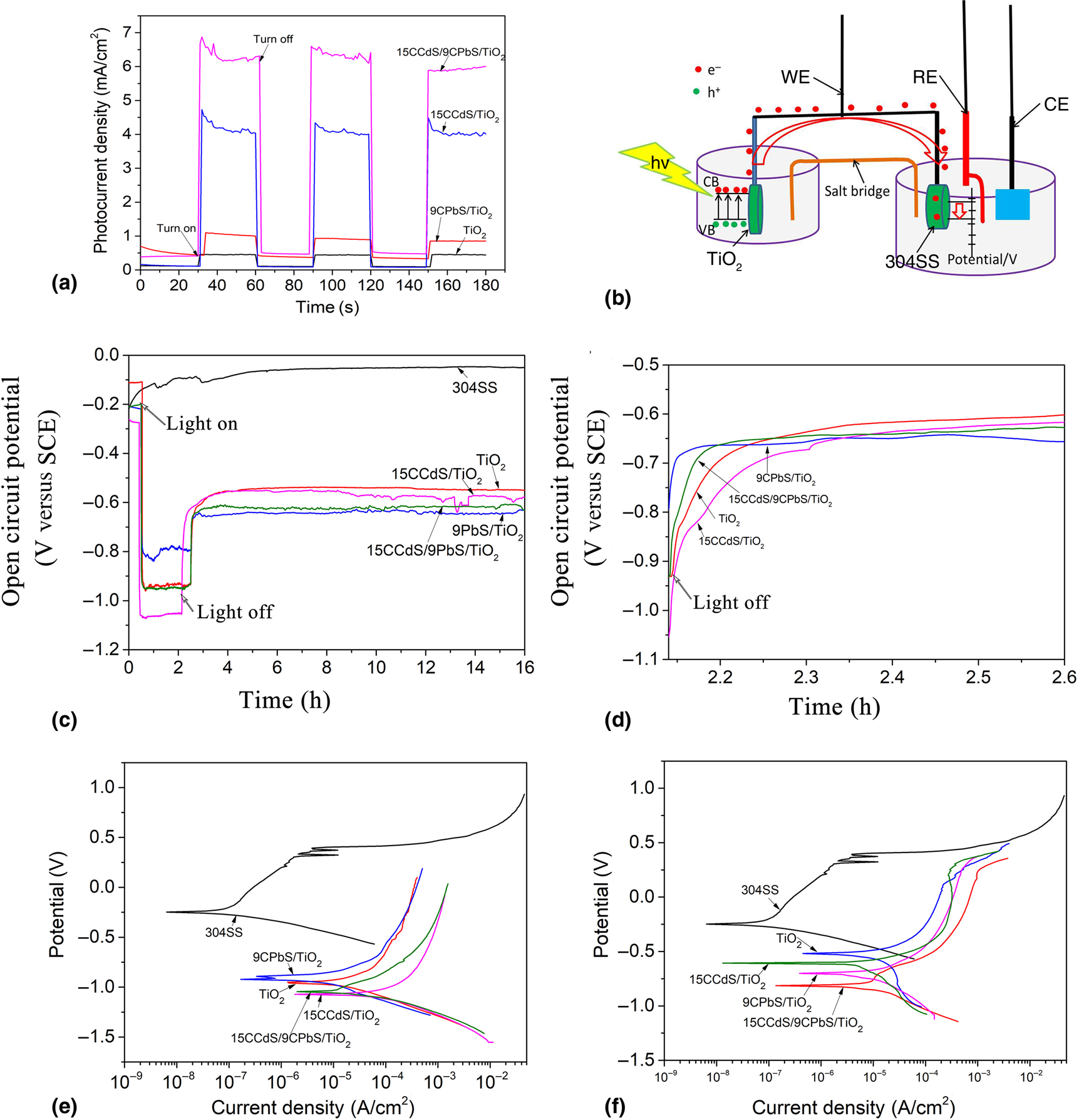
The PEC performance of the prepared photoanodes was tested firstly. In order to observe the durability of photocurrent response, the PEC experiments were carried out by the chopped light with an individual period of 30 sata 0 V versus SCE [Fig. 2(a)]. The corresponding photocurrent density values of TiO2 NTAs, 15CCdS/TiO2, 9CPbS/TiO2, and 15CCdS/9CPbS/TiO2 were determined to be 0.4, 0.9, 4.1, and 6.0 mA/cm2, respectively. Pure TiO2 NTAs demonstrated the lowest photocurrent density value, due to its slow visible-light absorption, while better performance was observed for CdS or PbS sensitized TiO2 NTAs. Interestingly, the photocurrent density of the 9CPbS/TiO2 NTAs film was inferior to that of the 15CCdS/TiO2 NTAs film, since CdS QDs enhanced charge separation and carrier injection. The 15CCdS/9CPbS/TiO2 film showed the highest photocurrent density due to the consistent band edges of CdS and PbS in multivariate heterojunction, thus leading to superior PEC performance. The fast photoresponse under periodic off/on cycles corresponding to a negligible photocurrent density in the dark condition and an instantaneous high value in the presence of simulated sunlight, demonstrated photocurrent generation in the highly durable photoanode.
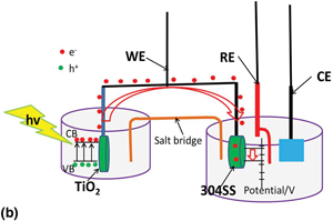
(a) Photocurrent response in the chopped light of the photoanode films; (b) schematic diagrams of the PCP test system; photocurrent response in the chopped light of the photoanode films; OCP curves of 304SS in 3.5% NaCl solution coupled with photoanode films: (c) complete OCP curves under illumination and darkness; (d) the trend of potential rise after removal of sunlight illumination; PDP curves of 304SS in 3.5% NaCl solution coupled with the photoanode films: (e) under solar light illumination; (f) under dark conditions

Open Circuit Potential (OCP) analysis of 304SS coupled with photoanodes
A schematic diagram of the PCP system, which consists of CdS/PbS/TiO2 and 304SS, is shown in Fig. 2(b). The photogenerated electrons produced by CdS/PbS/TiO2 can be effectively transmitted to 304SS, which reduces the potential of 304SS and achieves PCP.
OCP plots of 304SS in 3.5% NaCl solution coupled with the photoanode film under simulated solar illumination and the dark state are shown in Figs. 2(c) and 2(d). The data were collected for 16 h in total with the first 2 h in solar illumination and remaining 14 h under the dark state. It can be seen that the OCP of 304SS is about −0.1 V versus SCE all the time, but when 304SS was coupled with the photoanode films, the OCP drastically shifted to the negative axis under illumination. The photogenerated voltage of TiO2, 15CCdS/TiO2, 9CPbS/TiO2, and 15CCdS/9CPbS/TiO2 under sunlight illumination are −0.95, −1.08, −0.82, and −0.96 V, respectively. When the sunlight was removed, the OCPs slightly increased due to the loss of photogenerated voltage, but the OCPs became stable at −0.55, −0.60, −0.66 and −0.63 V for more than 2 h. This is due to the fact that photoanode films/salt bridges/stainless steels form a capacitor which can store photogenerated electrons. Such a structure can maintain a stable negative Fermi level of photoanodes and thus protect 304SS for a long time even in lower illumination conditions. The stored potential and electricity can secure a more negative potential of 304SS than self-corrosion potential for more than 14 h in the dark, indicating that these films have excellent ability to store photogenerated electrons and have great potential in the application of PCP.
As the final stable potential of the system is affected by the structures of the photoanodes, it is not the only criterion for evaluating the performance of PCP. Another important criterion is the trend of potential shift after the removal of the illumination [Fig. 2(d)]. The potentials of all 304SS films rise gradually, indicating that the photoanodes are slowly releasing the stored electrons. The potential increase of 304SS was gentle when coupled with 15CCdS/TiO2, indicating that photogenerated electrons can be released slowly under the action of heterojunction created between semiconductor CdS and TiO2. When 304SS was coupled with 15CCdS/9CPbS/TiO2, the potential increased slowly. The final stable potential was also lower, indicating that the photoanode film 15CCdS/9CPbS/TiO2 has a better ability to store photogenerated electrons. In comparison, the potential increases more quickly when 304SS was coupled with 9CPbS/TiO2. This shows that the heterojunction of PbS and TiO2 does not improve the electron storage ability of the photoanode film, so the performance of PCP was poor. It can be summarized that the band alignment between PbS and TiO2 was not ideal which can be improved by the introduction of CdS SQDs.
Potentiodynamic polarization (PDP) analysis
PDP curves of the bare 304SS and 304SS coupled with the photoanode film system are shown obtained in the presence [Fig. 2(e)] and absence [Fig. 2(f)] of simulated sunlight. PDP curves clearly show that the potential of 304SS has an obvious negative shift when coupled with photoanode films, similar to the results of OCP. The potential of 304SS decreased significantly when coupled with 15CCdS/TiO2 and 15CCdS/9CPbS/TiO2 either in the illumination or in the dark conditions. The corresponding corrosion current density of the 304SS when coupled with photoanode films was larger and increased further when 304SS was coupled with the 15CCdS/TiO2 and 15CCdS/9CPbS/TiO2 films in both illumination and dark conditions. The more negative corrosion potential of 304SS showed better corrosion resistance and the larger current density may be attributed to the creation of the photogenerated electrons from the photoanode film.[Reference Zhou, Zeng and Zhong3] The enhancement of electrochemical reaction at the SQD/TiO2 interface resulted from the polarization effects.
The fitting results of PDP curves of the 304SS and the 304SS coupled with photoanode films are shown in Supplementary material, Table S2. The change in potential and the current density value compared with that of bare 304SS were more significant when 304SS coupled with 15CCdS/TiO2 and 15CCdS/9CPbS/TiO2 under illumination. The potential and current density values of 304SS when coupled with 15CCdS/TiO2 and 15CCdS/9CPbS/TiO2 films were −1.09 and −1.07 V, 97.7 and 55.1 µA/cm2, respectively, indicating that the photoanode films have better PCP performance for 304SS, due to the fact that 15CCdS/TiO2 NTAs and 15CCdS/9CPbS/TiO2 NTAs demonstrated better PEC performance. The separation and transmission mechanism between electrons and holes in semiconductor heterojunctions can explain this problem reasonably and has been discussed in detail in the PEC performance section. Under dark conditions, 15CCdS/TiO2 and 15CCdS/9CPbS/TiO2films coupled with 304SS still have larger current density values (9.0 and 10.1 µA/cm2) than others, and the corresponding potential value was also more negative, indicating that the 15CCdS/TiO2 NTAs and 15CCdS/9CPbS/TiO2 NTAs can reflect the better PCP performance regardless of illumination and dark conditions.
The voltage range of the 304SS in the OCP and PDP measurement were −1.09 to −0.52 V. It is necessary to investigate whether polarization occurs within this voltage range (detailed results shown in Supplementary Fig. S2). It can be seen that in this voltage range, the current density increases gradually from −0.3 to −0.03 mA/cm2 in the range of voltage scanning and then stabilizes. There was no polarization phenomenon with a sharp change of current density. It shows that the charge transfer layer between solution and interface will not be destroyed in this voltage range, and 304SS was always in the cathodic protection state.
Electrochemical Impedance Spectroscopy (EIS) analysis
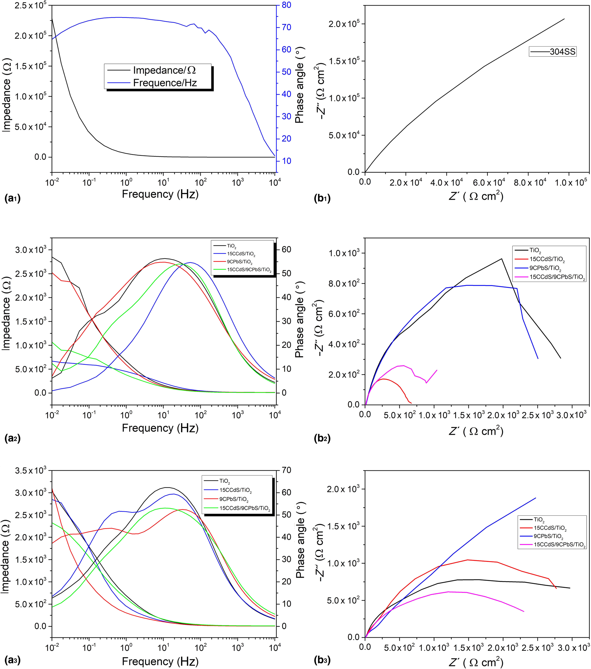
In nondestructive conditions, EIS tests can obtain significant quantitative and qualitative data regarding corrosion performance. Figure 3 series (a) show the Bode plots of the 304SS and the 304SS coupled with photoanode films. The 304SS has the highest impedance value in the low-frequency region shown in Fig. 3(a1). When the 304SS was coupled with photoanode films [Figs. 3(a2) and 3(a3)], the impedance value was lower by nearly four orders of magnitude than that of 304SS. The impedance of 15CCdS/TiO2 and 15CCdS/9CPbS/TiO2 are also relatively small both in illumination and dark conditions. It can be explained that under the simulated sunlight, the photogenerated electron accumulation inside the nanotubes increases the photocurrent density. This leads to their transmission to the 304SS, further increasing the charge density of 304SS in the PCP state. The Faraday electrode's release speed may be accelerated, increasing the capacitance of the membrane and that of the double layer.[Reference Zhu, Xu, Hu, Zhang, Du and Lin6,Reference Li, Lin, Li and Lin19] In the dark condition, the overall trend is similar to the illumination condition as shown in Fig. 3(a3), as well as 304SS coupled with 15CCdS/TiO2 and 15CCdS/9CPbS/TiO2 have the lower impedance value under illumination than in the dark condition. Since the photogenerated electrons transferred in the dark state are stored in the photoanode film, the number of photogenerated electrons must be less than under continuous sunlight illumination. The smaller impedance value may be due to the continuous transmission of electrons from the photoanode film and the structure of this connection in the dark state like in bio-sensitized solar cells and bio-nano interfaces.[Reference Das, Wu, Song, Hou, Koch, Somasundaran and Priya31,Reference Das, Asmara, Patra, S, Bista, Somasundaran, Rusydi, Barbiellini and Venkatesan32]
EIS curves of 304SS and 304SS coupled with photoanode films in 3.5% Nacl solution: (a1) Bode curves of 304SS; (b1) Nyquist curve of 304SS; (a2) Bode curves of 304SS coupled with photoanode films under sunlight illumination; (b2) Nyquist curves of 304SS coupled with photoanode films under sunlight illumination; (a3) Bode curves of 304SS coupled with photoanode films under the dark state; and (b3) Nyquist curves of 304SS coupled with photoanode films under the dark state.

Nyquist curves of the 304SS and 304SS coupled with photoanode films are shown in Fig. 3 series (b), and Figs. 3(b1)–3(b3) are 304SS, 304SS coupled with photoanode films under sunlight illumination and the dark state, respectively. It can be seen from the Nyquist curves that the capacitive anti-arc of the 304SS coupled with the photoanode film is concentrated into a circular arc without obvious tailing. It is due to that the 304SS is in the PCP state, the surface electron density is high, the Faraday resistance significantly reduced and the Faraday reaction and the mass transfer process are faster.[Reference Li, Lin, Li and Lin19] The 304SS coupled with 15CCdS/TiO2 and 15CCdS/9CPbS/TiO2 has the smaller arc radius both in sunlight illumination and dark conditions, indicating that there is more electron transfer from the photoanode film to 304SS, giving the electrode interface higher reactivity and the better PCP performance. The overall trend that has appeared in the Nyquist curves are consistent with Bode curves.
Fitting circuit Rs-(Rct|Q2) was used to extract the fitting data of 304SS, and Rs-(Rf|Q1-(Rct|Q2)) corresponding the data of 304SS coupled with photoanode films (detailed circuit diagrams are shown in Supplementary Fig. S3). Rs is the solution resistance, the resistance and capacitance of the membrane electrode in the high-frequency region are expressed as Rf and Q1, respectively, while Rct and Q2 represent the low-frequency charge transfer resistance and double-layer capacitance respectively.
The corresponding fitting results are detailed in Supplementary material, Table S3. It can be seen that the Rct value under illumination is significantly lower than in the dark state, which can be explained by the fact that the photoanode film produces photoelectrons which are transferred to 304SS. This increases the electrochemical reaction rate and the current rate. At the same time, it can be seen that under the dark conditions, the Rct values of 304SS coupled with 15CCdS/TiO2 and 15CCdS/9CPbS/TiO2 NTAs films were smaller than that of other systems, due to the continuous transmission of photoelectrons under the dark state. Combined with the OCP results, the composite films of 15CCdS/TiO2 NTAs and 15CCdS/9CPbS/TiO2 NTAs display improved PCP performance. Corresponding Rs and Rf values of 304SS coupled with 15CCdS/TiO2 and 15CCdS/9CPbS/TiO2 were relatively smaller than that of other photoanode films in the illumination or dark conditions.
In summary, the potential trend of 304SS and the final stable potential show that 15CCdS/TiO2 and 15CCdS/9CPbS/TiO2 have the best PCP performance.
Microstructure analysis
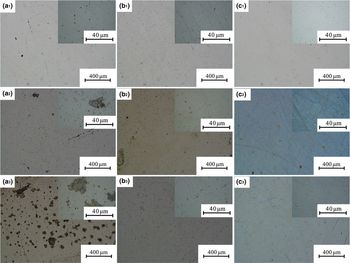
In order to study the protective performance of the 304SS under PCP over long periods, the immersion experiments of 304SS coupled with the 15CCdS/9CPbS/TiO2 film were carried out for 3 months. Two hours of illumination was given at the beginning of each month, while at the same time the immersion experiments of bare 304SS and 304SS coupled with the photoanode film in the dark state were carried out for comparison. The morphologies of the samples after 3-month illumination are shown in Fig. 4. The series (a) (bare 304SS) images show some pitting corrosion appeared after one month of immersion which gradually expanded after 2 months. When the immersion time reached 3 months, the corrosion pits increased in size significantly (about 30 µm). Series (b) of Fig. 4 shows the images of the 304SS coupled with the 15CCdS/9CPbS/TiO2 photoanode film under different immersion times in dark conditions. As can be seen from the images, a small amount of pitting corrosion occurred in 304SS in 1 month. The number of pits increased slightly and the size of individual pits expanded with the increase in immersion time until 3 months. Compared with the bare 304SS, the corrosion in the coupled system is not obvious, indicating that the 304SS is better protected. This is due to the potential difference between 304SS and the photoanode film as the potential of 304SS in the system can be effectively controlled. Series (c) of Fig. 4 shows the 304SS coupled with the 15CCdS/9CPbS/TiO2 photoanode film under illumination. It can be seen from the images that 304SS is almost not corroded. There are only several small pits after 2-month immersion time, less than in series (b), indicating that 304SS has obtained the desired PCP. The photoanode film prepared in the experiment can protect 304SS for long time periods (3 months), which also show the durability and stability of the photoanode films.
Microstructure of the bare 304SS and 304SS under PCP lasted 3 months: Series (a) is the 304SS under different immersion time: (a1) 1 month, (a2) 2 months, and (a3) 3 months; Series (b) is the 304SS coupled with the 15CCdS/9CPbS/TiO2 photoanode film under different immersion time in dark conditions: (b1) 1 month, (b2) 2 months, and (b3) 3 months; and Series (c) is the 304SS coupled with the 15CCdS/9CPbS/TiO2 photoanode film under different immersion time and every month given 2 h sunlight illumination: (c1) 1 month, (c2) 2 months, and (c3) 3 months.

Conclusion
15CCdS/9CPbS/TiO2 films were successfully fabricated using the SILAR technique by depositing CdS and PbS QDs on the TiO2 nanotubes in our current study. The PEC performance of the composite photoanode film and the cathodic protection effect have been enhanced when 304SS was coupled with the composite photoanode film. Specific conclusions are as follows:
1) Composite photoanode films were successfully prepared by the SILAR, the QDs evenly distributed inside and outside of TiO2 NTAs, and the TiO2, CdS, and PbS exist as crystals in the composite photoanode films.
2) The PEC performance of the co-composite photoanode film (15CCdS/9CPbS/TiO2) has been significantly improved with the highest photocurrent density of 6 mA/cm2, 15 times higher than that of pure TiO2 NTA films.
3) The composite photoanode films (15CCdS/TiO2 and 15CCdS/9CPbS/TiO2) enhances PCP performance for 304SS. The photoanode film prepared in the experiment can protect 304SS for a long time (3 months), which also show the durability and stability of the photoanode films.
Supplementary material
The supplementary material for this article can be found at https://doi.org/10.1557/mrc.2019.151.
Acknowledgments
The authors are grateful for the financial supports from Beijing Natural Science Foundation (No. 3192013) and the Beijing Key Laboratory of Pipeline Critical Technology and Equipment for Deepwater Oil & Gas Development (BIPT 2018001).