1. Introduction
In a missile test range, multiple radars operating in different frequencies are deployed to provide the trajectory information of the flight vehicles under test. In modern scenarios, various types of intermediate-range ballistic missiles (IRBM), inter-continental ballistic missiles (ICBM), cruise missiles, and anti-satellite missile flight experiments are conducted from test ranges, and these exercises demand precise trajectory generation by the tracking radars. The tracking radars calculate the range of the targets based on the rectilinear propagation of the radar waves in free space.
Depending on the operating frequency of the radars and the class of the missile being tracked, the radar data suffers from various kinds of errors due to atmospheric effects on the electromagnetic signals used by the radar. These errors are mainly categorised as ionospheric delay and tropospheric error. Refraction of the radar signals in the troposphere depends on the elevation angle of the radar antenna and the prevailing meteorological conditions. Some studies on tropospheric refraction for C-band tracking radars have been presented (Varaprasad et al., Reference Varaprasad, Bhaskara Rao and Rao2012), and the results can also be extended in the case of the S-band operation. For the S-band tracking radars, in addition to the tropospheric error, the contribution of ionospheric delay is also prominent, and it should be considered with importance as it affects the target range calculations in real time.
The ionosphere is a layer of charged particles that stretches from approximately 45 km to 965 km from the surface of the Earth and is characterised by the total electron content (TEC) value (Datta-Barua et al., Reference Datta-Barua, Doherty, Delay, Dehel and Klobuchar2003; NASA, 2020). TEC has diurnal and seasonal variations due to several factors directly affecting the kinematic density of the electrons in the layer. The actual value of TEC calculated from any point on the surface of the Earth depends on geographical location, local time, season, and associated solar and magnetic activities (Teunissen and Montenbruck, Reference Teunissen and Montenbruck2017). Standard models, e.g., Klobuchar (Klobuchar, Reference Klobuchar1987, Reference Klobuchar1996), global ionosphere map (GIM) (Mannucci et al., Reference Mannucci, Wilson, Yuan, Ho, Lindqwister and Runge1998), GRAPHIC (Misra and Enge, Reference Misra and Enge2006), GIVE (Dasgupta et al., Reference Dasgupta, Paul and Das2007), NeQuick (Nava et al., Reference Nava, Coisson and Radicella2008), WARTEK (Andrei et al., Reference Andrei, Chen, Kuusniemi, Hernandez-Pajares, Juan and Salazar2009), Petrie (Petrie et al., Reference Petrie, Hernández-Pajares, Spalla, Moore and King2011), etc. help to theoretically predict the TEC values to a reasonably good accuracy, and therefore can be utilised for the ionospheric delay calculations. These models are used for the signals from satellite-based navigation systems generally transmitting the signal in the L-band of radio frequency signals. The models have their relative merits and demerits and have varying accuracies at different geographical locations. Extensive research to calculate the ionospheric delay in S- and C-bands was done for radars during the pre-GNSS era using meteorological parameters (Schmid, Reference Schmid1966). However, these calculations are complex, predictive, and do not use the information on the status of the ionosphere during the time of launch of missiles and hence were not very fruitful. Hunt first used the GNSS signals in the L-band to calculate the TEC (Hunt et al., Reference Hunt, Close, Coster, Stevens, Schuett and Vardaro2000) and combined TEC values, and refined the data using dual frequency radars (Hunt et al., Reference Hunt, Rich and Ginet2012) for the prediction of ionospheric error for radars in the test range. The models provide a theoretical prediction of associated delays for the S-band tracking radar and can be used to correct the trajectory of the missile under test. However, to date, no experimental study has been done to use the GNSS S-band signals directly to calculate the ionosphere error of the radars operating in the S-band.
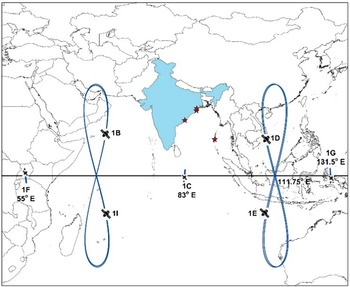
Currently, multiple satellite-based navigation systems are in operation, both global (GPS, GLONASS, Galileo, and Beidou) and regional (e.g., Navigation with Indian Constellation [NavIC] and Quasi Zenith Satellite System [QZSS]). These systems are generically designated as the Global Navigation Satellite System (GNSS). The use of GNSS for ionospheric monitoring is an established and popular technique (Akala et al., Reference Akala, Doherty, Valladares, Carrano and Sheehan2011; Goswami et al., Reference Goswami, Paul and Paul2017); several detailed and very recent reviews of the technique can be found in the literature (Su et al., Reference Su, Jin and Hoque2019; Yuan et al., Reference Yuan, Jin and Hoque2020; Jin et al., Reference Jin, Gao, Yuan, Guo, Calabia, Ruan and Luo2021, Reference Jin, Wang and Dardanelli2022). NavIC is a regional satellite-based navigation system designed, deployed, and maintained by the Indian Space Research Organization (ISRO). The NavIC constellation consists of seven satellites placed in high Earth orbits (HEO). Three of these satellites (named NavIC 1C, 1F, 1G) are in geostationary Earth orbit (GEO) and four satellites (named NavIC 1B, 1D, 1E, 1I) are placed in inclined geosynchronous orbit (IGSO) (Department of Space, 2020) as shown in Figure 1. NavIC signals are transmitted in L5 (1176 · 45 MHz) and S-bands (2492 · 028 MHz) of the radio frequency (RF) spectrum. Signals from all seven satellites are always received from any point in India excluding an extremely small part in the northeast, where at least six satellites are always visible (Dan et al., Reference Dan, Santra, Mahato and Bose2020). This typical constellation structure of NavIC with satellites placed in HEO offers unique advantages for ionospheric studies (Sharma et al., Reference Sharma, Gurav, Bose, Gaikwad, Chavan, Santra, Kamble and Vhatkar2019) from the service region and research has been done on the use of NavIC signals for atmospheric studies (Bhardwaj et al., Reference Bhardwaj, Vidyarthi, Jassal and Shukla2017). NavIC satellites continuously transmit the S-band signal, which is unique for the constellation and is not present in the case of other constellations. Therefore, NavIC presents an exclusive scope for continuous monitoring of the ionosphere using this S-band signal together with the standard L-band-based monitoring in its service area. This unique feature of NavIC S-band signal availability is exploited in this present study. Here the results obtained through the monitoring of NavIC signals are extended to mitigate the effects of the ionosphere on S-band tracking radars in real time to improve the target trajectory predictions experimentally instead of model-based theoretical predictions. Works on ionospheric study have been done exclusively for NavIC by various researchers (Venkata Ratnam et al., Reference Venkata Ratnam, Raghavendra Vishnu and Sree Harsha2018; Desai and Shah, Reference Desai and Shah2019, Reference Desai and Shah2020, Bhardwaj et al., Reference Bhardwaj, Vidyarthi, Jassal and Sukla2020; Dey et al., Reference Dey, Joshi, Chhibba and Sharma2021) but they were primarily are restricted to ionospheric research. This research paper is based on the results of experiments using the S-band NavIC signal for real-time improvement of S-band tracking radar performance in a missile test range.
S-band radar locations (brown stars) and NavIC satellite footprints

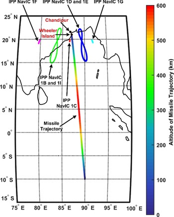
In this paper, we investigate the potential of the S-band NavIC data collected from a missile test range situated at Chandipur, Odisha, India, using conventional methods to calculate the TEC from the location, and to use the results in computing the associated ionospheric delay for the S-band tracking radars for improvement of the real-time tracking accuracy. The applicability of the method is typically suitable for the flight azimuth angles of the ballistic and anti-satellite missiles launched from the test range, as these coincide with the azimuthal look angle of the geostationary NavIC 1C satellite. This typical situation offers the benefit of a similar ionospheric pierce point (IPP) location both for the NavIC satellite and for the tracking radar signals, as shown in Figure 2. The flight azimuth directions of the missiles launched from this test range towards the Indian Ocean are also shown in the figure. NavIC 1C is a geostationary satellite; therefore, the corresponding IPP from Chandipur remains approximately fixed. This fixed IPP location is closer to that of the radar under consideration in comparison with the other NavIC GEO satellites, and therefore the S-band signal from the NavIC 1C satellite is considered for this study. The present work shows that the results of ionospheric probing by the NavIC S-band signal of satellite 1C at the test range from satellite 1C can be conveniently used for the improvement of the real-time missile trajectory estimation by the S-band radar at the site.
NavIC IPP with respect to the test range location and missile flight azimuth

2. Effect of ionosphere on S-band radar signal
The ionosphere is a dispersive medium for RF waves and the refractive index of the medium is a function of the frequency. The refractive indices are also functions of the electron density of the medium, and the Earth's magnetic field. RF signals undergo group delay as they pass through the ionosphere and the signals experience significant refraction. The delay of the signal depends on the number of free electrons present along its path. This results in a delay for the pseudo-range (increased value) and an ionospheric phase advance for carrier phase measurements (decreased value) (Teunissen and Montenbruck, Reference Teunissen and Montenbruck2017).
As per International Telecommunication Union recommendations (ITU Recommendation, 2013), the ionospheric group delay is expressed as

In the case of radar, f denotes the tracking radar frequency, and NT denotes the TEC (electrons per square metre).The group delay can be expressed in metres by multiplying by the speed of light, i.e., by 3 × 10⁸ m/s, and we obtain the equation shown below, which is also used by Hunt et al. (Reference Hunt, Close, Coster, Stevens, Schuett and Vardaro2000).

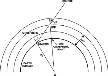
where l represents the one-way signal path length, and ne is the electron density along the path of the electromagnetic signal, integrated from the target to the radar antenna phase centre. More precisely, ne is called slant TECs, which represents the total number of electrons in a cylindrical column of length l and unit cross-section (1 m2), and it is measured in the unit of 1016 electrons per square metre. A two-dimensional ionospheric single-layer model is used (Petrie et al., Reference Petrie, Hernández-Pajares, Spalla, Moore and King2011) to convert the slant TEC values (TECs) to vertical TEC values (TECv) using a simple mapping function. The model assumes that the ionosphere is compressed into a thin shell at the peak ionospheric height of 350 km as shown in Figure 3. The height of the thin shell is taken as the altitude of the IPP and is calculated as described by (Sharma et al., Reference Sharma, Gurav, Bose, Gaikwad, Chavan, Santra, Kamble and Vhatkar2019). The collocated radar and NavIC receiver are shown as ‘station’ in the figure, the ‘source’ is the missile under test which is aligned with the direction of the NavIC 1C geostationary satellite.
Ionospheric single layer model. (‘Station’ is the location of the radar and the NavIC receiver, ‘Source’ is the instantaneous position of the missile under test that is aligned with the NavIC 1C geostationary satellite, ‘IPP’ is the point where the RF signal from the source pierces the ionosphere)
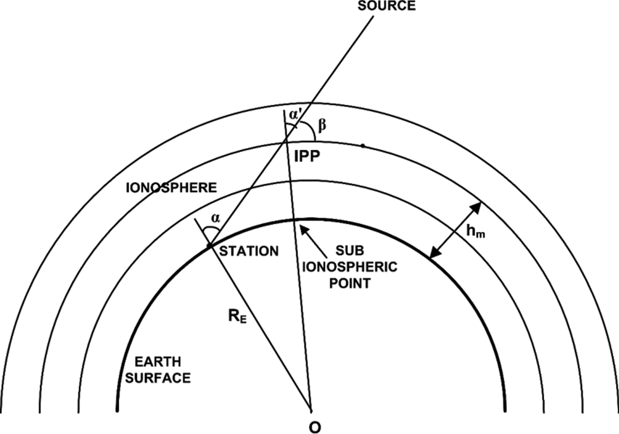
For any observation location, the TEC through a particular IPP is obtained as TECv = TECscos ($\alpha ^{\prime}$ ), where

RE is the mean radius of the Earth and hm represents the height of the maximum electron density from the surface of the Earth, α and $\alpha ^{\prime}$ are the zenith angles at the observation station and the IPP, respectively. In general, the value of hm is taken as the height corresponding to the maximum electron density at the F2 layer peak (Varaprasad et al., Reference Varaprasad, Bhaskara Rao and Rao2012). The peak altitude ranges from 250–350 km at middle latitudes and from 350–500 km for location at the equatorial latitude of Chandipur (21 · 43994°N, 87 · 0149° E). Typical values for RE and hm at Chandipur are considered to be 6,375 · 3012 km and 450 km respectively on theWGS84 reference ellipsoid (Smith, Reference Smith1987; Petrie et al., Reference Petrie, Hernández-Pajares, Spalla, Moore and King2011). Now from Equation (2) the one-way group delay of the radar signals while passing through the ionospheric plasma can be expressed as

The ionosphere delay (and the TEC) for a particular location can be calculated using different models like GIM, the Klobuchar model, etc. (Klobuchar, Reference Klobuchar1987, Reference Klobuchar1996; Mannucci et al., Reference Mannucci, Wilson, Yuan, Ho, Lindqwister and Runge1998). In this study, TEC is calculated using the ionospheric grid model as this model is used for NavIC (ISRO, 2017).
The objective of the work is achieved in two steps. First, the ionospheric delay in S-band is calculated using the NavIC S-band signal during an active missile test mission in the direction of the missile trajectory from the test range, and then the results are used for the S-band radar signals for different radar antenna elevation angles for correction of missile trajectory estimation. The corresponding methodology and results are presented in the subsequent sections.
3. Correction of tracking radar data using NavIC
The locations of the seven NavIC satellites on the equator or during crossings of the equator are shown in Figure 1, and the IPPs for the NavIC signals from the radar location at Chandipur are shown in Figure 2, together with the missile trajectory. The figures show that the IPP of the NavIC 1C satellite is in the same direction as the flight azimuth of the missile path. NavIC 1C being a geostationary satellite, the IPP and the look angles (elevation, azimuth) remain almost fixed with regard to the radar location, and therefore the NavIC 1C satellite is chosen as the most suitable satellite as the boresight source of S-band signal for calibration of the S-band radar located at Chandipur.
The ionosphere layer has a height of approximately 1,000 km through which the one-way NavIC signal passes while the missiles go up to an altitude of around 800 km. The radar signal tracking the missiles has a two-way journey (transmitted signal and reflected back echo signal) through the ionosphere and therefore experiences a more prominent effect. Therefore, from a practical viewpoint, the one-way 200 km altitude difference between the missile's apogee height and the height of the ionosphere as experienced by the NavIC signal is ignored for all practical purposes as it will contribute a negligible error. To begin with, the TECv from Chandipur is calculated using NavIC 1C data, and then the ionosphere group delay of the signal is calculated corresponding to the radar elevation angles.
3.1 Calculation of TEC at the Chandipur test range site using NavIC1C data
The operational frequency of the S-band tracking radar used at the test range is very close to the NavIC S-band signal; a collocated NavIC S-band-enabled GNSS receiver (ISRO IRNSS-GPS-SBAS receiver, ISRO-IGS NavIC Rx) is used to measure the $\textrm{TE}{\textrm{C}_v}$ and ionospheric delay in S-band.
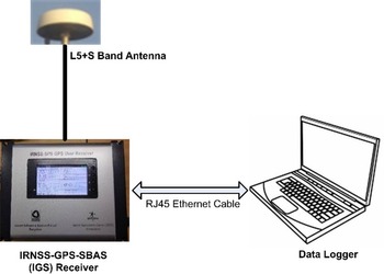
The ISRO-IGS NavIC receiver with the antenna placed with a clear view of the sky is installed at the test range, as shown in Figure 4. The receiver was operated in NavIC S-band only from 18:30 IST on 26 February 2019 to 10:30 IST on 27 February 2019, which includes the time of an active missile launch mission under consideration. From the raw data provided by the IGS receiver and vendor-supplied data extraction utility, ionosphere delay (iono-delay in metres) is obtained. It is to be noted that the calculated iono-delay is based on the ionosphere grid model and the TECs is calculated using Equation (5).

where ${f_s}$ = 2492 · 028 MHz is the NavIC S-band central frequency (ISRO, 2017).
Experimental setup for NavIC S-band data recording at the test range location

The average elevation angle of the NavIC 1C satellite from Chandipur is 64 · 5° and therefore the zenith angle is 25 · 5°. Thus, from Equation (3) we get,

and therefore,

Using Equation (5) the TECs values are obtained, and finally, the vertical TEC values are obtained using Equation (6),

The $\textrm{TE}{\textrm{C}_v}$ values at Chandipur for the NavIC 1C satellite are shown against the local time (IST) in Figure 5 as recorded during the night-time launch mission. The $\textrm{TE}{\textrm{C}_v}$
 values range from 7 total electron content unit (TECU) to 23 TECU. As usual, it is observed that TEC is lower during the quiet time before sunrise and becomes higher when the sun is up at the zenith.
TECν variation with time at the test range obtained using NavIC 1C data, 1 TECU = 1016electrons/m2

3.2 Ionosphere delay variation with the radar elevation angle
Ionosphere delay (ΔL in metres) for different elevation angles of radar is calculated by Equation (4) as $\Delta L = \frac{{40 \cdot 3}}{{{{({{f_{radar}}} )}^2}}}\sec (\theta )\; \textrm{TE}{\textrm{C}_v}$ , where θ represents the radar zenith angle, ${f_{radar}}$
 represents the radar operating frequency (in Hz). If the radar elevation angle is ${E_r}$
 , then using Equation (6)

If the TECs values can be calculated from the NavIC S-band signal from satellite 1C as per Equation (5), then the ΔL values in Equation (7) may be calculated continuously for the tracking radar operating in the same frequency band. Therefore, the results from the NavIC S-band signal monitoring can be directly used to calculate the real-time ionospheric delay for the S-band radars during the actual missile launch, and therefore, for the real-time correction of the target ranges.
Usually, tracking radars in test ranges uses the transponder (or beacon) mode of tracking the missiles. So, there will be two frequencies under consideration, one for the uplink or the transmit frequency, and the other for the downlink from the missile or the receive frequency. Let the frequencies for the transmitted and the received signals from and to the radar be$\; {f_{radar\_Tx}}$ and ${f_{radar\_Rx}}$
 respectively. Then the ionosphere delay during the radar signal transmission is

and the ionosphere delay during the reception of the signal is

Therefore, the total ionosphere delay during the round-trip signal path during the tracking of the missile is

Now, the TECs values calculated using the NavIC 1C signal using Equation (6) are used in Equation (10), and the ionosphere group delays corresponding to the radar elevation angles are calculated. The corresponding results are shown in Figure 6 and the expanded view is shown in Figure 7 for better visualisation of the ionosphere error values. A close inspection of Figures 6 and 7 reveals that the ionosphere delay decreases with increasing radar elevation angle Er. Around 19:00 IST on 26 February 2019, the ionospheric delay saturates beyond 60o elevation angle, during 03:00–05:00 IST, 27 February 2019 beyond the 15° elevation angle the delay saturates. Around 09:00 IST, this delay saturates after a 40° elevation angle. Thus, the time of the missile launch also plays a crucial role in the calculation of the ionospheric delay of the S-band radar signal.
Variation of round-trip ionospheric delay values for the missile trajectory with S-band radar elevation angle calculated using S-band signal from the NavIC 1C satellite. The colour bar on the right side represents different ionosphere delay values (metres)

Expanded view for lower S-band radar signal elevation angles. The colour bar on the right side represents different ionosphere delay values (metres)

Table 1 depicts the actual round-trip ionospheric delay values for a S-band radar during the observation period of the night-time missile launch mission. It may be seen that, at extremely low elevation angles (1° or 2°), the ionosphere delay goes up to 130 m. At radar elevation angles of between 5° and 10°, the delay varies between 10 and 20 m. At 10°–20° elevation angle, the delay ranges from 5 to 10 m. At 20°–30° elevation angle, the delay ranges between 1 and 3 m, and for 30°–55°, the delay ranges from 1 to 2 m. Above 55° elevation angle, irrespective of time, ionosphere delay saturates approximately at 1 · 5 m.
Round-trip ionosphere delay of S-band radar signals as calculated using the S-band signal from NavIC 1C at the Chandipur test range location during an active launch mission

The results shown in Table 1 imply that the ionospheric delay values calculated for the observation period using the NavIC S-band signal can be used to improve the accuracy of the S-band tracking radars by incorporating the delay in the final trajectory calculation. Thus, the NavIC S-band signal can provide the elevation angle and time-dependent ionospheric delay values during missile launch periods, which in turn, can be used to improve the real-time range estimation accuracy of the tracking radars. Along with the conventional applications, NavIC S-band signals may also be used for strategic purposes where very high real-time accuracy is needed.
The NavIC constellation consists of three geostationary satellites, and therefore, real-time ionospheric correction data may be generated through multiple observation locations that cover a large part of the missile trajectory tested from the Chandipur test range.
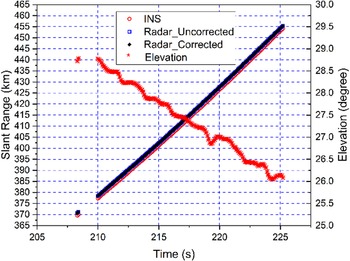
To validate the method proposed in this paper, data from a night-time missile test mission are used together with the in-situ NavIC data. Selected portions of the data have been presented in Table 2 for radar high elevation angle and in Table 3 for radar low elevation angle for comparison. Two small parts of the missile trajectory – one at the beginning of the mission with a high elevation angle and the other at a low radar elevation angle – are used here, as shown in Figures 8 and 9. In the figures, the on-board (inertial navigation system) INS-GNSS fused data as received through the telemetry channel from the missile under test is taken as the reference value for the missile slant range; in the figures, the slant ranges obtained from the INS-GNSS, radar elevation angle, the uncorrected slant range from the radar and the corrected radar slant range using S-band NavIC data are shown with regard to the observation time. It is seen in Figure 8 that, during the initial launch phase of around 215 s of tracking, for a slant range of around 400 km and higher radar elevation angles, the correction values are around 8 m as per the proposed method with regard to the reference INS-GNSS data. However, for the time around 575 s with the missile slant range around 2,200 km with very low radar elevation angles around 2 · 5°, the uncorrected radar slant range data deviates from the INS-GNSS data as shown in Figure 9 and the correction values are calculated to be around 130 m as per the proposed method and the uncorrected radar slant range data is improved to the corrected slant range data. Though the time of travel of the missile in this zone is very short, i.e., for 3–4 s, the analysis is important for correction of the trajectory information as this will improve the target and missile impact point analysis. This experiment validates the applicability of the proposed experimental method for slant range data correction of S-band radars using NavIC signals.
Comparison of radar range data for high radar elevation angles

Comparison of radar range data for low radar elevation angles

Radar slant range correction using the proposed method for high elevation angles during the initial phase of the mission

Radar slant range correction using the proposed method for low radar elevation angles during the subsequent phase of the mission

4. Conclusion
The paper presents a novel experimental approach to improve the real-time tracking accuracy of S-band radar at the Chandipur missile test range by ionospheric delay correction utilising co-located and concurrent NavIC S-band signals. For a particular night-time mission, the associated correction of the radar slant range is shown that validates the proposed method; the method may be extended for any launch mission period. The ionosphere delay decreases as the radar elevation angle increases, and beyond an elevation angle of around 55° the iono-delay values saturate around 1 · 5 m irrespective of the observation time, but for low radar elevation angles, the error values may be more than 100 m. The results clearly show that the ionospheric delay errors for the tracking radars operating in S-band can be corrected to improve the measured trajectory of the targets in real time. Depending on the mission-specific target trajectory, the ionospheric delay correction values can be calculated through co-located and simultaneous NavIC S-band observation. Correction of the radar range errors in real time would help in obtaining a more precise trajectory using S-band radars in case of complex missions like missile versus missile ballistic air defence and anti-satellite missions where the actual kinetic kill is of high importance. This may be an important strategic application of NavIC S-band signals beside the conventional position, navigation and timing (PNT) uses.
Future works in this regard would include studies on the ionospheric delay correction of S-band radar signals using concurrent NavIC signal observation from multiple points around the missile launch site, and the use of compact, low-cost S-band enabled NavIC modules for the purpose.
Acknowledgements
One of the authors (MG) thanks the Director, Integrated Test Range (ITR), Defence Research and Development Organization (DRDO) Chandipur for his constant encouragement and support while carrying out the present research work. The author AB acknowledges the Space Application Center (SAC-ISRO), Ahmedabad for hardware support.
Funding statement
The author AB acknowledges ITR, DRDO, Chandipur (Project Code: RD/ PI-20/ ITR-050) for financial support.
Competing interests
None.