Introduction
The key point of passive radars is the use of external transmitters of communication networks as illuminators of opportunity. A detailed explanation of passive radar principles can be found in [Reference Cherniakov1]. This technology has gained a great interest in latest decades. As a result, a number of passive radar systems for commercial and research purposes were developed up to date. They are based on similar operational principles but exploiting different illuminators of opportunity, such as FM radio, analogue TV, DAB, GSM, WiFi, DVB-T, etc. [2–Reference Kuschel, Heckenbach, O'Hagan and Ummenhofer8]. Third-party transmitters of digital broadcasting services, especially DVB-T, are most promising for target illumination due to expecting detection capabilities of passive radars utilizing signals of digital standards. In the near future, the DVB-T broadcasting services will be inevitably replaced by the next-generation DVB-T2 standard. Therefore, some research groups have already focused their investigations toward possibilities and features of exploitation of DVB-T2 transmitters by passive radars [Reference Kovalev and Veremyev9–Reference Winkler, Klöck and Edrich11].
The transition of the digital broadcasting infrastructure to DVB-T2 in Russia began in 2012, the year when a group of scientists at Saint Petersburg Electrotechnical University (ETU) started researches on the topic of passive radars. As a result of the research project, the experimental model and technical proposal for the design of passive radar system exploiting DVB-T2 for illumination purposes for air surveillance in urban areas were developed. The migration to second-generation digital video broadcasting services in Russia was successfully completed in 2015. By that time, the first experimental prototype of passive radar was developed and tested. Nowadays, a commercial version of two-dimensional (2D) DVB-T2 passive radar is available [12, Reference Vorobev, Barkhatov, Veremyev and Kutuzov13]. The developed passive radar is intended for detection, coordinate estimation and tracking of moving aerial, terrestrial, and sea surface objects in the protected area of important infrastructure and hazardous facilities.
Passive radar systems appear to be feasible candidates for protection of strategic objects and important infrastructure [Reference Kulpa, Malanowski, Misiurewicz and Samczynski14]. The features, technical specification, and detection capabilities of DVB-T2 passive radar developed place it in a line with other systems suitable for protection purposes. A serious threat for security comes from the increased availability and ease of use of unmanned aerial vehicles (drones). The detection and recognition of drones is a challenging task for the radar due to their small size, low radar cross-section, ability to fly slowly at low altitudes. Despite this, the 2D passive radar exploiting DVB-T2 transmitters for illumination demonstrate good performance for drone detection [Reference Barkhatov, Vorobev and Konovalov15]. In order to estimate and prevent a potential risk of drone collision with aircrafts, or its use for terrorist attacks, espionage activities, and others, it is important to have information about the target altitude.
The 2D DVB-T2 passive radar is capable to measure azimuth angle providing only latitude and longitude coordinates.
A possible solution for the realization of a 3D passive radar was introduced in [Reference Poullin and Flécheux16]. The discussed multistatic 3D passive radar using simultaneously three transmitters of DVB-T standard is able to provide 3D localization of the low altitude targets.
A different solution for 3D passive radar operating with a single transmitter of DVB-T2 standard is proposed in this paper. This 3D version of the passive radar extends functionality of the developed 2D passive radar [Reference Vorobev, Barkhatov, Veremyev and Kutuzov13]. A 2D non-equidistant antenna array is considered for exploitation in DVB-T2 passive radar instead of the linear antenna array used in 2D version to provide capability for estimation of elevation and corresponding altitude of the target.
2D passive radar
Specification
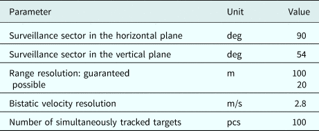
An operational principle of the passive radar is based on a calculation of cross-ambiguity function between the surveillance (echo) and reference signals. The signals of DVB-T2 transmitters with a bandwidth of 8 MHz resulting for the ideal case in range resolution of 20 m are used as an illuminator of opportunity.
A technical specification of the DVB-T2 passive radar is presented in Table 1. The features of the system allow to:
• detect and track moving targets;
• estimate the target range, velocity, and coordinates;
• display the target trajectories on the map;
• create special surveillance and alarm zones of interest;
• organize the remote operator position;
• consolidate the information from several passive radars into a common interface;
• access the history of detected targets and radar system running status;
• perform radar system integration with optical and infrared sensors;
• operate in real-time 24/7 mode in all weather conditions.
Technical specification of 2D passive radar

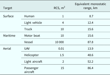
The detection capabilities were investigated during experimental campaign under different scenarios [Reference Barkhatov, Vorobev and Konovalov15]. The detection ranges are represented in Table 2 by equivalent monostatic values obtained for the effective radiated power of 5 kW and signal-to-noise ratio (SNR) of 13 dB under the assumption that the receiver and transmitter are allocated at the same position. As can be seen from Table 2, passive radar is able to detect almost any aerial, terrestrial, or sea surface moving target.
Detection capabilities of 2D passive radar

Configuration
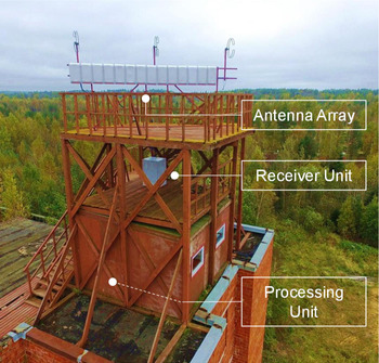
The developed DVB-T2 passive radar includes receiving antenna array, receiver unit, processing unit, software, and spare parts (Fig. 1).
Example of DVB-T2 passive radar arrangement.

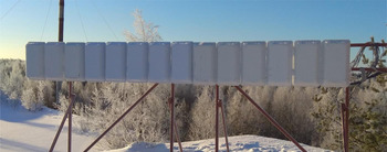
The antenna array receives echo-signals reflected from targets. Additional individual reference antenna element is intended to receive a direct signal of DVB-T2 broadcasting. The basic linear 14-element antenna array, which is shown in Fig. 2, provides a surveillance sector of 90° in azimuth and 54° in elevation. The standard DVB-T/T2 commercially available Antex CIFRA-12 panel antenna is used as the antenna element. The antenna array is mounted on a collapsible frame, which configuration can be determined by the required allocation conditions.
Front view of the linear antenna array.

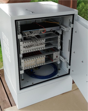
The receiver unit performs filtration, amplification, analog-to-digital conversion, and preliminary digital processing of signals incoming from the antenna array. The pre-processed data are transmitted to the processing unit for further processing. The receiver unit consists of signal receiving block, digital processing block, switch unit, cables and patch cords, automatic shutdown device, thermostats, and thermo cabinet with heating and cooler elements (Fig. 3). Thermo cabinet maintains a constant temperature of the operational environment, which allows outdoor allocation of the receiver unit.
Receiver unit in the thermo cabinet.

The processing unit obtains pre-processed data from the receiver unit and provides operation of the general and specific software of the passive radar system. It consists of an uninterrupted power supply, switch, and computing machine. The parallel processing techniques are realized in the graphics processing units in order to reduce the processing time and ensure a real-time radar operation. The general software performs primary processing with target detection, estimation of target coordinates, trajectories detection, and target tracking. More detailed information about general software is described in [Reference Vorobev, Barkhatov and Kutuzov17, Reference Konovalov18].
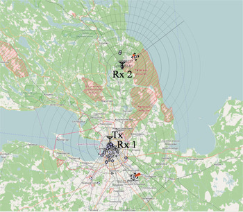
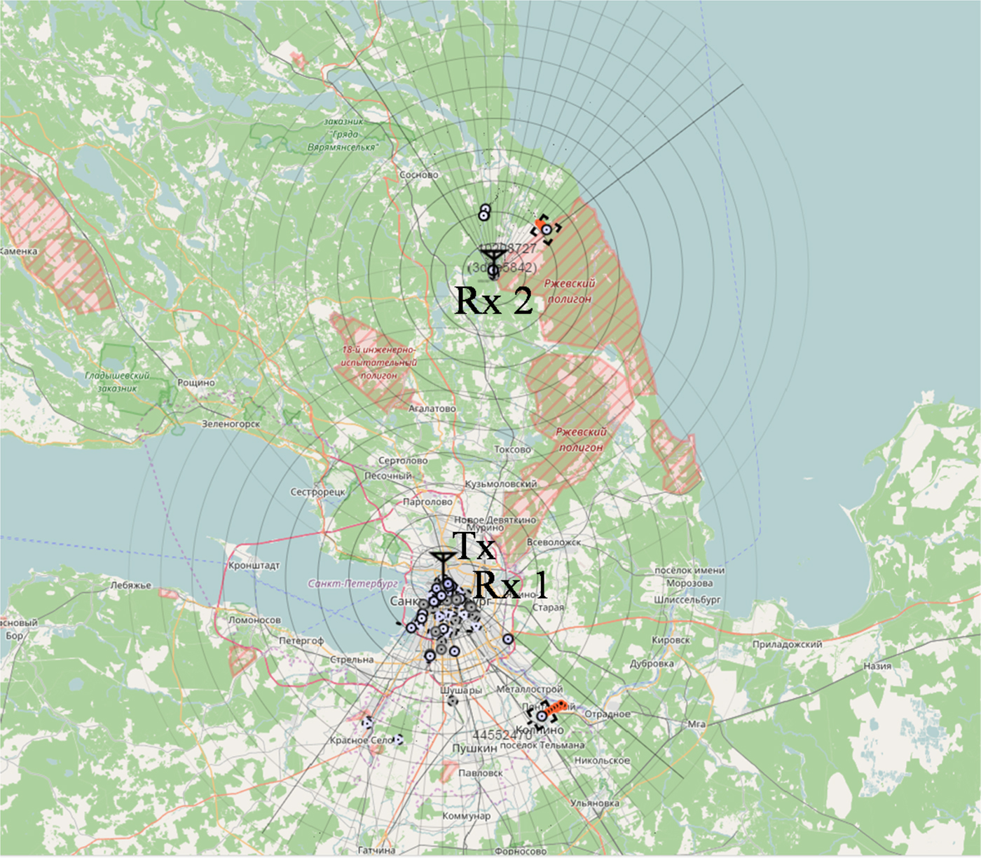
The passive radar can be managed by means of the user interface available over HTTP via Web browser of different desktop and mobile platforms. The main window of the user interface displays a passive radar surveillance area with marks of detected targets on a map as well as parameters of target trajectories. The user interface also contains a history of detected targets and radar system running status. The information from several passive radar systems can be consolidated in a common interface. For example, Fig. 4 shows a common interface of two individual passive radars exploiting the same DVB-T2 transmitter. The first passive radar (Rx 1) is allocated in urban conditions at a distance of 620 m apart from the transmitter, while the second (Rx 2) is 49.2 km far from it.
Common interface of two individual passive radars.
3D passive radar
Motivation for 3D passive radar
The developed 2D passive radar uses a linear antenna array where all antenna elements are arranged in a single row resulting in a lack of estimation of the elevation and consequently of the target altitude. Therefore, the antenna array needs an upgrade to allow altitude measurements and as a result to obtain a three-dimensional (3D) passive radar.
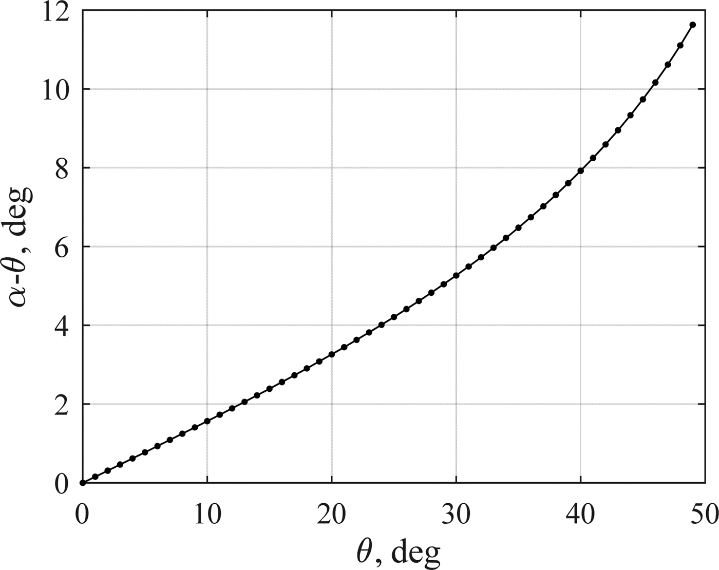
Another drawback of the linear antenna array is a localization error appearing for the target with a large elevation angle. A single-row array allows estimating the angle between the direction to target and the array normal to the plane containing the array and the target. If the elevation angle of the target is large, than the plane in which the angle between normal and direction to target is estimated using a single-row turns out to be strong inclined with respect to the horizontal plane. Meanwhile, the azimuth value estimated in the horizontal plane (with corrections to the sphericity of the Earth) is used for target localization. The estimation of target location based on the assumption that the direction to target is measured in the horizontal plane acquires an additional error if the direction to target, in fact, is measured in the elevation plane. The greater are the deviation from the normal and the elevation of the target, the greater is the difference between the direction to the target in the inclined plane and the azimuth of the target. This can be illustrated in Fig. 5, where the difference between the angles in the horizontal and inclined planes is shown depending on the angle in the inclined plane at an elevation angle of 30°. Here, θ is an angle in the inclined plane (measured angle of the target), α is an azimuth of the target. As can be seen, the error of azimuth measurement can achieve a significant value even at relatively small elevation angles (30° in this example). The range along the earth's surface and the oblique range can also differ markedly. If we do not take into account the sphericity of the earth (which in most cases is admissible), then Rg = Rrcosε, where R g – range along the earth's surface; R r – measured inclined range; ε – elevation.
Difference between the angles in the horizontal and inclined planes depending on the angle in the inclined plane at an elevation angle of 30°.

Another specific drawback of such single-row equidistant array originates from a use of commercially available antenna elements in order to reduce the cost of the radar. It is not always possible to find antenna elements with the dimensions that would provide antenna array pitch lower or equal to the half of the wavelength. For instance, the wavelength on the highest TV channel (60th) with DVB-T2 broadcasting in Russia is 0.38 m, whereas the width of the antenna element used in 2D passive radar is 0.33 m, which is significantly higher than a half of the wavelength. When the array pitch d is higher than the half of the wavelength λ then the sector of unambiguous angle measurement is  $2\arcsin (({\rm \lambda} /d)-1)$. The sector of unambiguous angle measurement is 17.4° for d = 0.33 m and λ = 0.38 m. The lower TV channel with DVB-T2 broadcasting in Russia operates with a wavelength of λ = 0.63 m resulting in the sector of unambiguous angle measurement of 130.8°. In many cases, the echo signals from large targets outside the sector of unambiguous azimuth measurement are still strong enough to be detected by passive radar. This results in impossibility for unambiguous determination which of several possible azimuths corresponds to a given detection. Therefore, the problem of azimuth ambiguity occurs for many detected targets.
Antenna array for 3D passive radar
In order to overcome the discussed drawbacks, the 2D non-equidistant antenna array was developed and investigated (Fig. 6). The antenna array consists of the same Cifra-12 antenna elements as for the 2D passive radar. Other constituent parts of the passive radar (receiver and processing units) remained the same as for the radar with linear single-row array.
Non-equidistant antenna array for 3D passive radar.

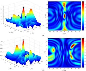
Such non-equidistant spacing of antenna elements is obtained by numerical simulation of the antenna pattern providing minimum achievable level of grating lobes. The examples of normalized patterns of the non-equidistant array simulated for the operational frequency of 586 MHz (central frequency of 35th DVB-T2 channel) are shown below. The pattern for the case when the beam is directed on zero-azimuth and zero-elevation is presented in Fig. 7(a) and for the case when the beam is directed on azimuth of α = 45° and elevation of ε = 35° (Fig. 7(b)). The pattern of such an antenna array still has the grating lobes originated from the element pitch higher than the half of the wavelength (especially in the vertical plane). However, the level of the grating lobes is lower than the main lobe of this antenna array in contrast to the equidistant array.
3D (left) and top view (right) non-equidistant antenna array patterns for the beam directed on zero azimuth and zero elevation (a); for the beam directed on azimuth of α = 45° and elevation of ε = 35° (b).

The passive radar with such a 2D non-equidistant antenna array can be considered as 3D passive radar, since it is able to measure the target coordinates in 3D space. The signal-processing scheme in 3D passive radar is organized as follows. The beams are formed applying Fourier Transformation to signals from eight antenna elements equidistantly allocated in the upper row of the array. The general processing techniques (starting from cancellation of strong copies of the direct signal to detection of the targets using constant false alarm rate algorithm) are applied to each beam. Further, for all the targets detected in the beams, the azimuth and elevation angles are refined using additional signals from eight antenna elements allocated non-equidistantly in the lower row of the array.
We assume that after the target detection by upper eight-element antenna array, there is only one target in a single cell of the range-Doppler surface. Both azimuth and elevation directions are estimated for each of the range-Doppler surface cell where the target was detected. So only the main lobe of the non-equidistant array pattern does matter. In these conditions, the grating lobe level is not important until it is lower than the main lobe level. The numerical simulation has shown that the maximum level of the grating lobes is 2 dB lower than the main lobe. In most cases, this allows estimating unambiguously azimuth and elevation angles of the detected target. According to the results of the numerical statistical simulation performed with the SNR of 3 dB in each antenna element, for 1000 repetitions there was no single case when the grating lobe exceeds the main lobe.
The use of only half of the antenna elements for target detection results in reduction of the detection range and degradation of the angular resolution. At the same time, the described approach significantly reduces the processing time in comparison with the solution when it is necessary to form large number of beams not only in azimuth but also in elevation. Since 3D passive radar exploits eight antenna elements for target detection instead of 14 ones used in 2D radar, its detection capabilities can be derived from Table 2 by dividing the equivalent monostatic range by  $\root 4 \of {14/8} = 1.15$, while the SNR decreases in 1.75 times.
Preliminary experimental results
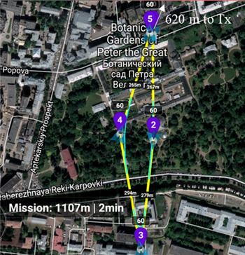
An experiment with the 3D passive radar was conducted to detect a small drone (DJI Phantom 3 quadrocopter) in urban scenario. The antenna array of 3D passive radar was allocated at the roof of ETU building at a distance of 620 m apart from the DVB-T2 transmitter. Figure 8 presents a screenshot from the Litchi application with a track of drone performing an automatic trip outward from the antenna array position (from point 5 to 3 in Fig. 8) and return back (from point 3 to 5). The flight altitude is 60 m from the allocation position of the antenna array. The passive radar and a smartphone used to control the drone were preliminarily synchronized in order to match the data from the drone's log file and data from the passive radar.
Experimental scenario for elevation measurement by 3D passive radar.

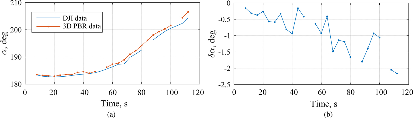
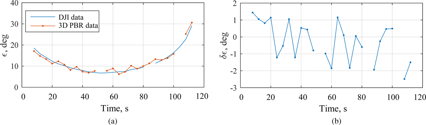
The drone elevation changed from 22.6° to 6.7° during the outward flight and from 6.7° to 29.1° during the return flight. Minimum and maximum azimuth values were 182.9° and 204.4°, respectively. The azimuth values measured by 3D passive radar in comparison with calculated from drone log data and their difference δα are shown in Fig. 9. In the same way, the elevation angles and the difference between measured and calculated values are presented in Fig. 10. The gaps at the plots corresponding to data from passive radar occur because there were no drone detections during some scans (for instance when the Doppler shift of the reflected signal was equal to zero). The gaps in the drone data are mainly because at some moments there were interruptions of the connection between the drone and its control unit. As a result, localization data of the drone was not recorded to the log file.
Azimuth values measured by 3D passive radar and calculated from drone log data (a); difference between measured and calculated azimuth (b).

Elevation values measured by 3D passive radar and calculated from drone log data (a); difference between measured and calculated elevation (b).

Despite the small amount of experimental data, the obtained results seem to be promising. The maximum deviation of the elevation measured by 3D passive radar from the calculated value is about 2°. In order to obtain a statistically reliable estimation of azimuth and elevation errors using the antenna array described above, we plan to conduct a series of experiments. In each experimental campaign, the flight of the drone will be specified in a way that both azimuth and elevation angles vary within a wide range.
Conclusion
The passive radar exploiting third-party DVB-T2 transmitters for illumination purposes was developed. The passive radar is feasible for detection, coordinate estimation and tracking of moving aerial, and terrestrial and sea surface targets. The configuration and technical specification of the 2D passive radar were presented. The use of 2D antenna array with non-equidistantly allocated antenna elements allows the realization of the 3D passive radar for 3D localization of the small low-altitude aerial targets. The first experimental results show the possibility to measure not only azimuth but also elevation and consequently target altitude by the passive radar exploiting low-cost commercially available antennas with the horizontal size greater than a half of the wavelength and the vertical size greater than the wavelength.
Author ORCIDs
Evgenii Vorobev, 0000-0001-6637-2374.
Acknowledgement
The work was financially supported by the Ministry of Education and Science of the Russian Federation under the Project ID RFMEF157817X0242.
 Aleksey Barkhatov received the Engineer Degree from St. Petersburg Electrotechnical University “LETI” (Russia) in 1998. He is currently a Researcher at the Research Institute of Radioelectronic Systems for Emergency Forecasting “Prognoz” of the same University. He authored more than 30 scientific publications. His research interests focused on digital signal processing, spectrum analysis, multistatic radars, and passive coherent location.
 Evgenii Vorobev received the B.S. degree from St. Petersburg Electrotechnical University “LETI” (Russia) in 2012 and double M.S. degree from the same University and Ilmenau University of Technology (Germany) in 2014. He is currently a Ph.D. student at St. Petersburg Electrotechnical University “LETI”. He co-authored more than 20 scientific publications. His research interests include design of passive radar systems, target recognition, and digital signal processing.
 Vladimir Veremyev received the Ph.D. degree from St. Petersburg Electrotechnical University “LETI” (Russia) in 2000. He is currently a Director of the Research Institute of Radioelectronic Systems for Emergency Forecasting “Prognoz”. Since 2003 he is a member of the St. Petersburg Arctic Academy of Sciences. He authored and co-authored over 100 scientific publications, including four monographs. His research interests focused on complex ecological monitoring, complex questions of the radar systems design, and multiband radars for aerial and maritime surveillance.
 Vladimir Kutuzov received the Doctor of Science degree from St. Petersburg Electrotechnical University “LETI” (Russia) in 1997. From 2009 to 2018 he was a Rector of St. Petersburg Electrotechnical University “LETI”. Currently he is a Professor, Head of the Department of Radio Engineering Systems at the same University. He is an author of over 200 scientific publications, including nine patents. His research interests include radar systems design for sea surface surveillance.