


Introduction: The Replicate Coring System as a Control System
The desire was to develop a drill that possesses the capability of drilling out of an existing parent borehole and to do so at the parent borehole’s ‘uphill’ side (see Fig. 1). This implies information and governance in two areas: (1) control, i.e. the drill must know ‘where it is’ in relation to ‘where it should be’ and, if there is a discrepancy, calculate updated set points to correct the error; and (2) actuation, i.e. the drill must possess the capability of positioning and steering itself in a direction determined by the control system. These two fundamental functions form the foundation of the overall system and were therefore part of the basic concept from the outset. On a fundamental level, the control problem can be broken down into control in the horizontal and vertical planes.
Definition of uphill side. Note that deviating on the borehole’s uphill side implies working against gravity.

Forces, Horizontal Plane
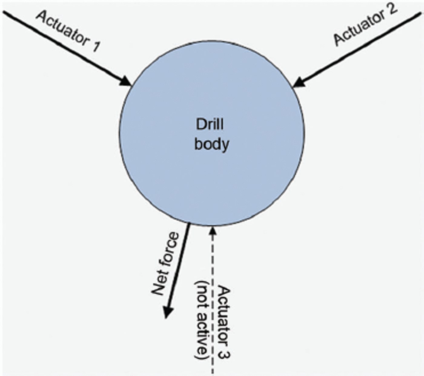
The drill system achieves part of the actuation aspect by means of six mechanical actuators located on the drill body. The six actuators are placed as two sets of three actuators where each set is part of a drill section called an actuator section. Two such actuator sections are used to steer the drill. Each actuator section serves the main purpose of providing one net horizontal force. This is achieved through the combination of two forces as shown in Figure 2.
Cross-sectional view looking from the top down. Two actuators are working to produce one net force in the desired direction.
The mechanical design and aspects thereof are described by Reference Gibson, Johnson, Shturmakov, Mortensen and GoetzGibson and others (2014). The modular design of the actuator section was tailored to suit the existing modularity of the deep ice-sheet coring (DISC) drill (Reference Mason, Shturmakov, Johnson and HamanMason and others, 2007). Each actuator section makes use of three brush-type electric d.c. motors, each of which drives an actuator by means of reducer, lead screw and linkage. Of further importance is that for each such actuator channel a linear variable differential transformer (LVDT) provides feedback to the control system allowing it to receive real-time information on the location of each actuator.
The amount of force required for each of the three actuators can be calculated using Newton’s laws and vector algebra. Taking this approach, a table with required actuator forces for a given angle of net force can be constructed. Figure 3 shows a graphical representation of such a table.
Graphs of required forces from the three actuators. y-axes are normalized, i.e. for a target azimuth of 110°, channel 1 should be at 0% of full force (retracted), channel 2 at 98% and channel 3 at 65%.

The drill circumference is divided into 360°. Thus if a net force in a direction of 110° is desired, actuators 2 and 3 are active while 1 is retracted; 2 and 3 are actuated at 98% and 65% of maximum force, respectively, to achieve the desired direction of net force. An important aspect is that since brush d.c. motors have shaft torque proportional to armature current, the force output from a given actuator channel is proportional to current, albeit with an adjustment factor proportional to the angle of the actuator arm relative to the drill body.
As mentioned, the drill uses two actuator sections, and the net force from each can be selected such that they push the drill toward the borehole’s uphill side. Figure 4 shows an actuator section being tested in the laboratory. A collar was made to simulate the borehole, and early version electronics were in place to drive the actuator section. The table represented graphically in Figure 3 was implemented and used to verify basic operation of the actuator section.
Photograph of an actuator section during a laboratory test. The two actuators nearest the camera are extended with different forces. Marks along the collar edge are used to indicate azimuth.

Forces, Vertical Plane
To push the drill toward the uphill side, the d.c. motor currents are set such that they cause a combination of four forces that ‘land’ the drill at a desired azimuth. This is shown in Figure 5 for two modes of operation: (1) ‘initial angle’, where the actuator sections push in opposite directions; and (2) ‘side push’, where they push in the same direction. It should be understood that Fa and Fb are each made up of two forces from two actuator arms.
Conceptual view of the replicate coring drill in the borehole. Two modes of actuation are shown: initial angle and side push.

Depending on the desired azimuth, amount of desired force, angles of individual actuators and mode of operation, the electronic system must provide appropriate voltage and current to the actuator channel motors. This needs to occur in concert with navigational information from the drill’s navigation module. These topics along with derivative functionality are described in the following sections, which detail several aspects of the replicate coring system control module.
Replicate Coring Control Module (RCM)
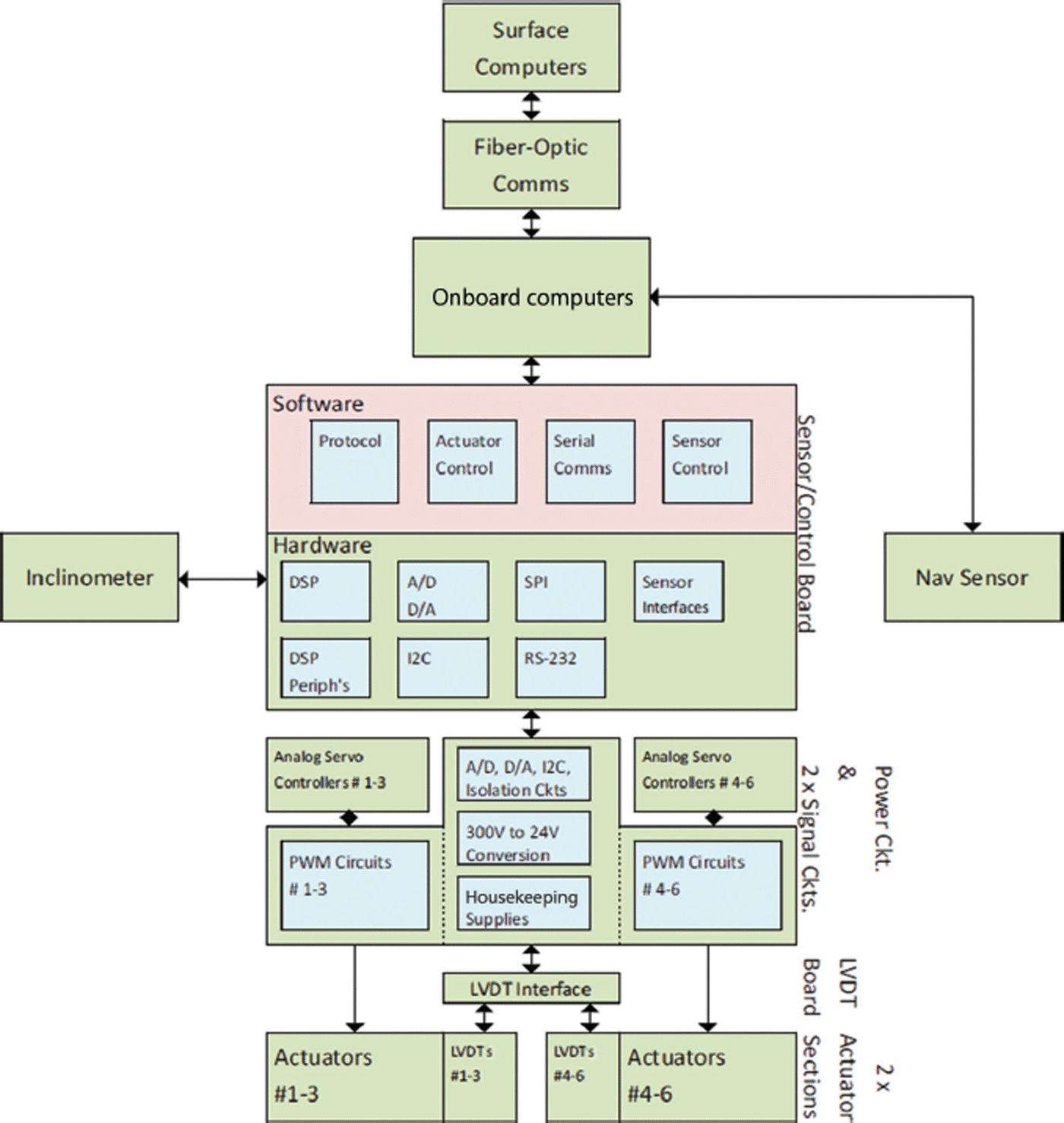
The replicate coring control system can be described in terms of its functional blocks as shown in Figure 6, which provides some indication of the amount of electronics, software, electromechanical and mechanical functions used to achieve effective navigation and adequate pushing forces. It should be mentioned that the block diagram largely reflects the modularity of the system design itself. Modularity proved to be a valuable design aid during the development of the system.
Overall block diagram view of the replicate coring system. Major system members are represented functionally, providing an overview of the system complexity.
Servo channels
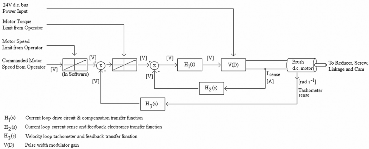
The servo channels are represented in Figure 6 by the analog servo controllers and pulse width modulation (PWM) circuits and, ultimately, the actuators themselves. Each of the six electromechanical actuators requires a dedicated servo channel responsible for closed-loop control of the d.c. motor speed and torque. These two parameters are controlled by controlling the motor armature voltage and current. No tachometer or torque-transducer is used to provide feedback, as this would increase wiring and connector complexity beyond capacity and add further complexity. Instead the decision was made to use d.c. motors because these show close near-linear relation between torque and current, and speed and voltage. Thus, by designing servo controllers to control these two parameters, speed and torque control can be achieved with good accuracy. The overall servo loop was mostly hardware implemented in the interest of alleviating processor load and reducing timing requirements to the RCM processor. Figure 7 shows the block-level design of a single servo channel.
Block diagram of one of the six servo channels. A two-loop design is used; the torque loop was nested within the voltage (or speed) loop. Note that the tachometer sense is simply the motor armature voltage (which is approximately proportional to motor speed).
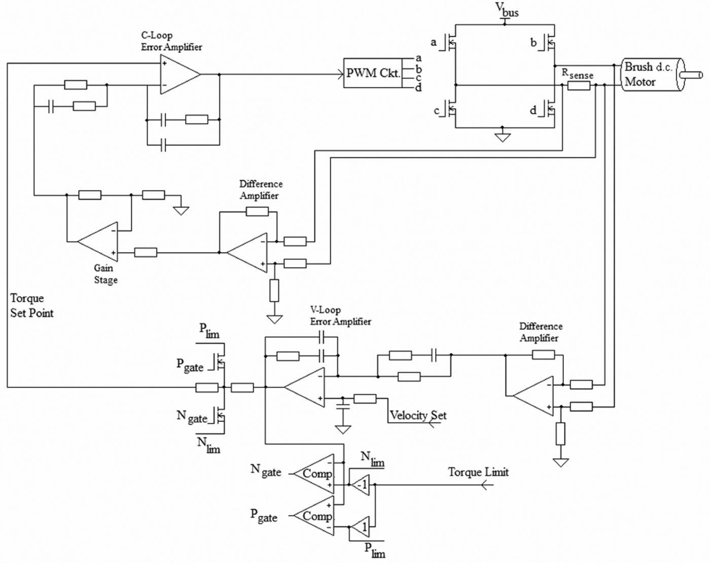
The power stage was implemented using a MOSFET (metal–oxide–semiconductor field effect transistor)-based H-bridge integrated into a single transistor outline package. Analog electronics were used to measure armature voltage and current for speed and torque control. An op-amp-based design allowed closed-loop control of voltage and current. Figure 8 shows the hardware design of a servo channel.
Simplified schematic of a servo controller. The two important control inputs, torque limit and velocity set, are shown. When the operator adjusts the ‘effort’ value this translates into a voltage on torque limit.
In order to maximize the density of the design, the servo channels were split in such a way that the analog servo controls were on one circuit board while the power stages were on a separate ‘mother board’ along with other electronics. The mother board was named the ‘power board’ and the servo control boards named ‘signal boards’.
The operation of the replicate coring system is dependent on each actuator supplying the correct amount of force at any given time. However, due to the lead screw, linkages, etc., in the actuator sections, the setting of d.c. motor currents alone is not adequate to ensure the correct force on the actuators. Any external event that would cause an actuator to be compressed inwards (e.g. from the drill sliding in the borehole into a narrower diameter, a common occurrence during replicate drilling where borehole geometry changes significantly) would not be detectable through the servo motor current. The compression of the actuator would result in a higher than intended force leading to inaccuracy in navigation. To counter this shortcoming, the velocity profile was introduced, effectively resetting the forces regularly by winding the motors inwards briefly before returning them to the desired force and speeds in the outward direction. This concept is shown in Figure 9, where A 1 represents outwards travel and A 2 inwards travel.
The velocity profile used to ensure that the force on an actuator is reset every few seconds, maintaining navigation accuracy.
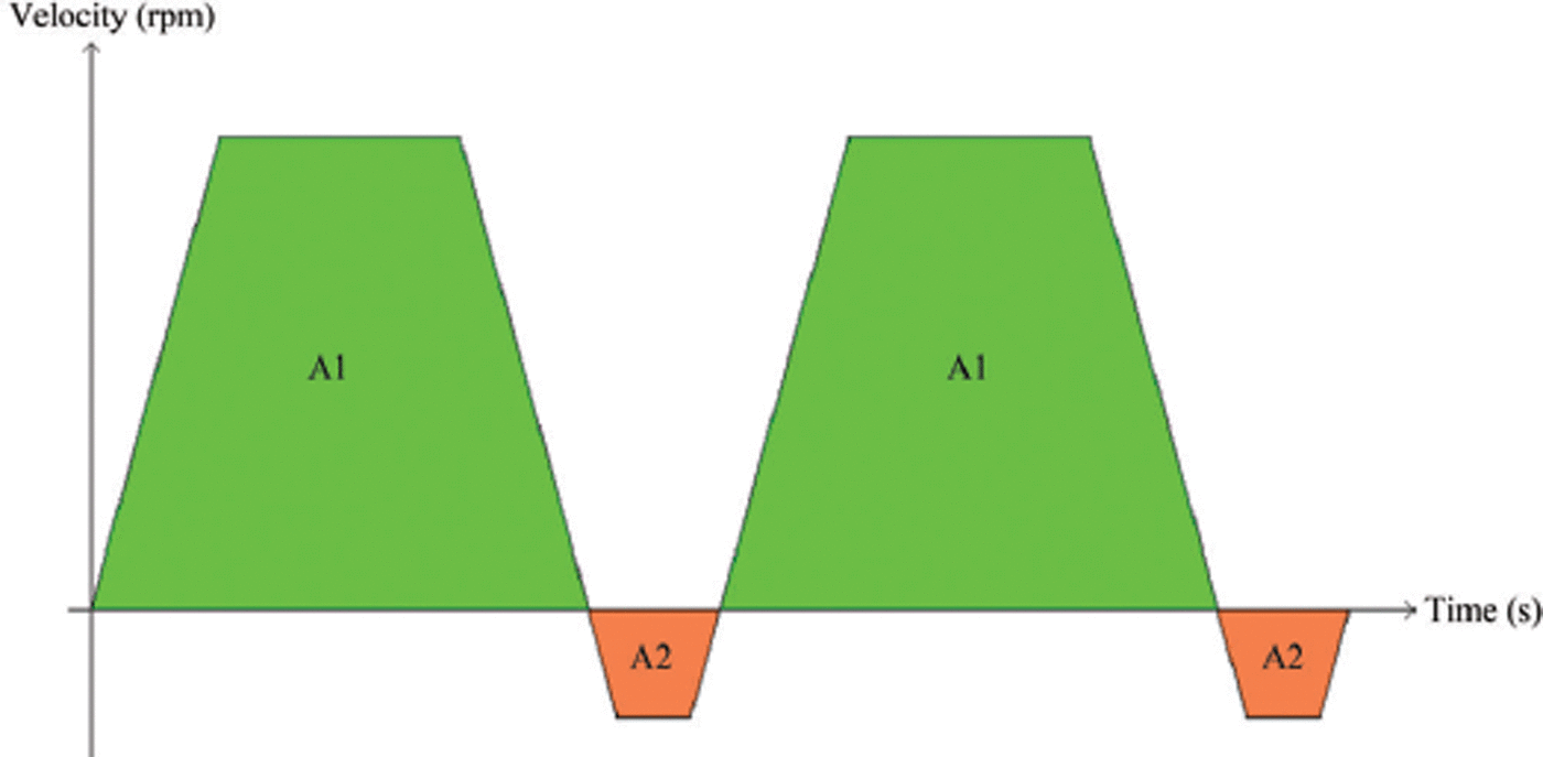
It should be noted that when an actuator is contacting the borehole wall, the inward motion is small enough to not remove the actuator from the wall; merely it briefly reduces the force. Owing to compliance in the mechanical system, the actuator remains in contact with the wall during this brief retraction. In reality, retraction is ∼200 ms while a total period is 2 s. Therefore the duty cycle is typically ∼90%. The disturbance caused by the velocity profile is therefore fairly limited and does not adversely affect overall operation. When an actuator has finished its inward cycle, it will begin its outward cycle using the speed and torque set points calculated previously. These are the set points show in Figure 8 as torque limit and velocity set. During the velocity profile cycling, the torque limit stays constant while velocity set is varied as per the velocity profile.
LVDT channels
Six LVDT channels are used to measure the physical location of each of the six actuator arms. To collect this information in real time, six LVDT drive interfaces had to be established electronically. A circuit board, the LVDT interface, was created specifically for this purpose. Its basic design is shown in Figure 10 and is based on an integrated circuit (IC) from analog devices: AD698.
Block diagram of the RCM LVDT board. The use of switches and an IO (input/output) expander permitted six LVDTs to be interfaced to one AD698 IC.
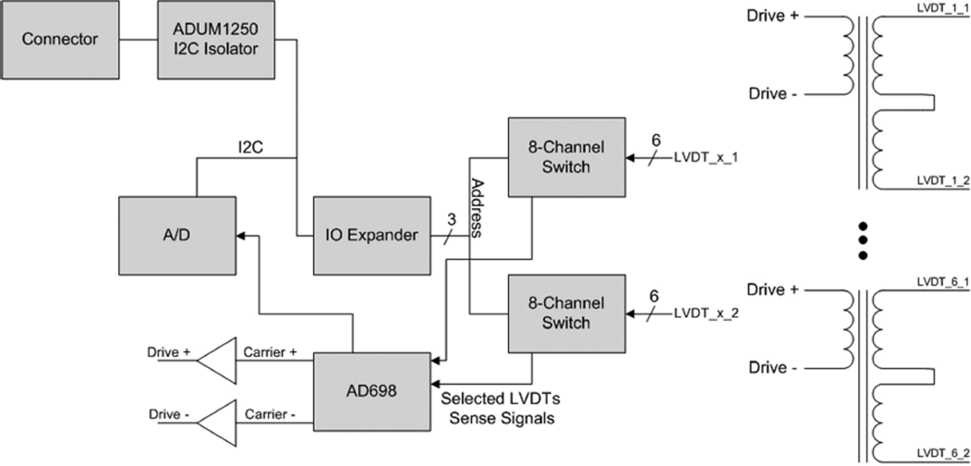
The I2C isolator was introduced to prevent failure propagation in the event of power connecting to an LVDT signal wire as a result of a wiring fault. The LVDT is powered from the control power supply of the DISC system (Reference Mortensen, Sendelbach and ShturmakovMortensen and others, 2007).
Analog-to-digital (A/D) and digital-to-analog (D/A) interface
The power board functionality is shown in Figure 11. It houses an A/D and D/A interface in addition to the six power stages mentioned earlier. The digital interface is required in order to communicate with the sensor/control board housing a digital signal processor (DSP). The digital interface was implemented using 16 A/D channels and 16 D/A channels communicating via an isolated I2C serial interface. The isolation barrier was introduced as a means to block conducted noise between various system modules as well as prevent failure propagation. In particular the switching noise from the six power stages and various power supplies were of concern with regard to noise contamination.
Simplified block diagram of the power board, which serves as a mother board for four other circuit boards.
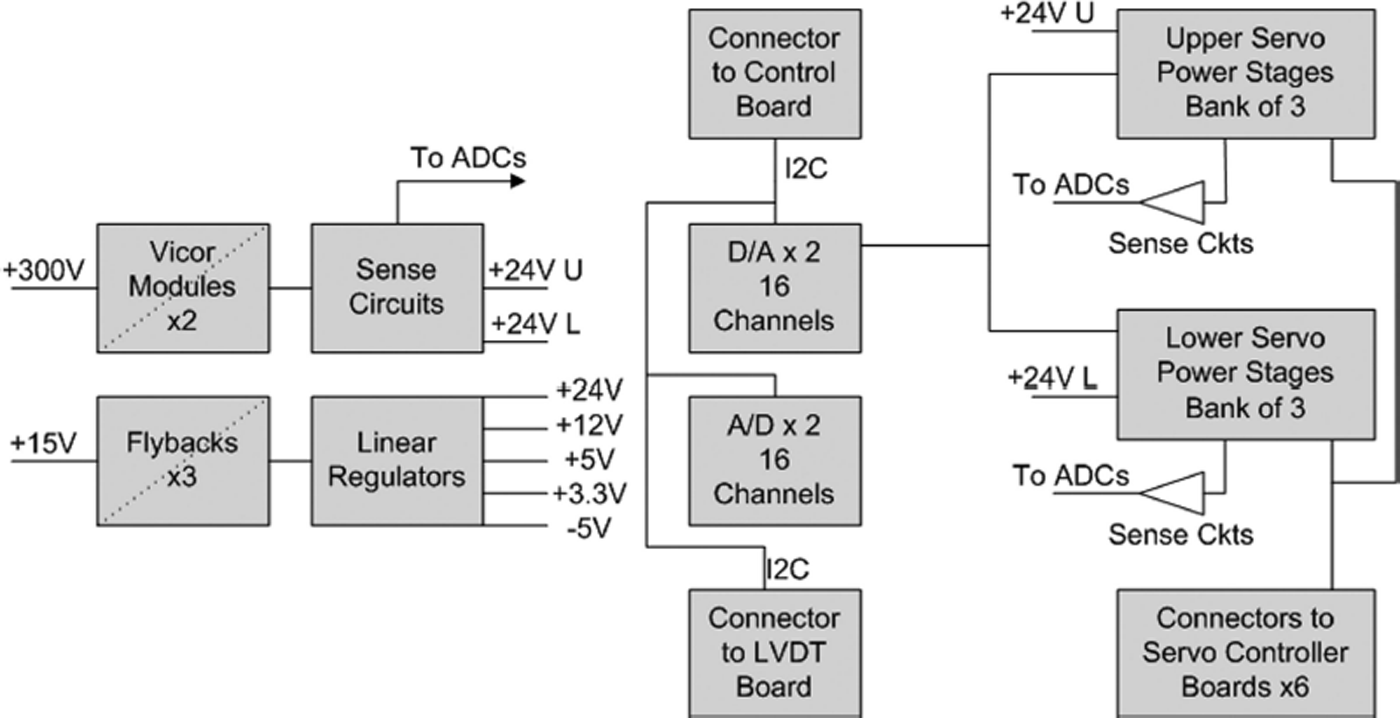
The six power stages were based on a PWM controller of type UHC3525 and an H-bridge of type LMD18200. The H-bridge was supplied in a transistor outline (TO) package and was mounted on the bottom side of the printed-circuit board (PCB) so it could be conduction cooled by the instrument section baseplate. The A/D and D/A interface collected motor currents and voltages as well as voltage and current from the two Vicor modules. The speed and torque set points to the six servo drivers were also channeled through the interface.
Power supplies
The replicate coring system was designed to operate such that the power board, LVDT board and sensor/control board are on separately referenced power supplies. In other words, the power architecture uses multiple grounds for noise and failure propagation control. The power board includes three isolated power supplies: two for 300 V to 24 V conversion and one for low-power housekeeping purposes. The 24V supplies were used to provide power to the six motor drivers. The power supplies were off-the-shelf devices from Vicor and integrated into the power board design as any other part in the design. They were powered from the DISC system’s motor power supply (MPS) (Reference Mortensen, Sendelbach and ShturmakovMortensen and others, 2007) with 300 V d.c. This is a useful feature as it means that the power stages can be turned off by remotely disabling the MPS. This is a useful aid in managing heat build-up during drilling operations. Each of the two Vicor modules is connected to a sensing circuit monitoring the module’s output voltage and current. These data are collected by the A/D and D/A interface and can be accessed via the system’s protocol. Thus this information is available to the operator at the surface, enabling assessment of the system’s ‘health’ and power usage.
The housekeeping power supply was designed as three flyback converters operating in parallel, two of them as current sources and the third as a current source with an outer voltage control loop. This design approach allows the use of small-sized surface mount technology (SMT) parts and avoids any bulky magnetic components that would be difficult or impossible to fit in the limited space available between the power board and the controller board. The output rails are transformer-isolated for noise control, and linear post regulators are used for fine regulation of the rails going to the various consumers on the power board and elsewhere.
Sensor/control board
As can be seen in Figure 6, the RCM includes a board housing a processor along with a multitude of sensor-related electronics. The processor was a Freescale device of type 56F8037, which includes a number of peripheral functions useful for replicate coring control. Among these are A/D, D/A, I2C (a type of serial ‘two-wire’ communications bus), UART (universal asynchronous receiver/transmitter), SPI (serial peripheral interface) and GPIO (general purpose input/output). The sensors and their electronics are mostly the same as for the DISC drill sensor board (Reference Mortensen, Sendelbach and ShturmakovMortensen and others, 2007). However, one new addition included specifically for the purpose of replicate coring is the inclinometer. This is a two-axis device from VTI Technologies (now Murata), part number SCA100T-D01. This device is introduced functionally as part of the sensor/control board but is physically located at the instrument section upper end cap in order for it to be in the horizontal plane during drilling. It is communicated with a SPI bus. Figure 12 shows the inclinometer board mounted for testing on a sine plate. The sine plate along with gauge blocks allow accurate testing of inclinometer inclination.
Inclinometer board in a test mount.

RCM Physical Design
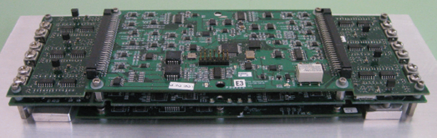
The RCM consists of six circuit boards: power board (or mother board), two signal boards (housing the analog servo controllers), LVDT board, sensor/control board and inclinometer board. The two signal boards (analog servo control) are identical. While the inclinometer board is located separately on the upper end cap, the remaining five boards were designed such that the power board served as the mother board for these boards. The Vicor modules and H-bridges were installed on the bottom side of the power board such that they could be conveniently cooled by the instrument section baseplate. Figure 13 shows how the five circuit boards that make up the RCM were designed to fit together. The Vicor modules and other power electronics were screwed onto the baseplate for heat dissipation.
Photograph of a finished RCM on a test stand. Five circuit boards establish the various functions required to govern and drive the six actuator arms, communications, etc.
Angle, Azimuth and Effort
In order to make the operation of the replicate coring drill more user-friendly, the terms angle, azimuth and effort are used in the user interface. Azimuth refers to the heading that the drill takes with respect to geographic north. For various reasons, as the drill traverses the borehole it tends to spin around its axis as its vertical position changes, therefore changing its local reference frame. The sensors and actuator arms of the drill are rigidly attached to the drill body, causing their reference frame to spin along with the drill. If azimuth were ignored, the drill would only be able to deviate relative to its local reference frame, leading to swerving deviations. Instead, the software continuously reads the drill’s azimuth heading and uses it as an offset term to keep the drill deviation heading in a globally static direction. An onboard navigation module allows the drill orientation in space to be queried regularly. The navigation module is an off-the-shelf device from 3DM (Reference Mortensen, Sendelbach and ShturmakovMortensen and others, 2007).
By having this azimuth correction factor, the user is able to give the drill an angle with respect to a fixed reference frame (north–south–east–west). Therefore the software is set up such that the user inputs an angle between 0° and 360° to the drill and the drill uses its measured azimuth to calculate the required local heading at that specific moment. This process allows the drill to always deviate in the same direction regardless of its local orientation in the borehole, which gives the drill the capability to re-enter existing deviations on separate downhole trips.
In addition to azimuth and angle, drill maneuvers are simplified for the user by means of effort. The user is able to send one effort value for the high set of actuators and one for the low set. The RCM converts these efforts into the actuator forces of section II with all the adjustment factors and standardization that is needed. This process gives the user standardized and finite control of the tilting of the drill without having to worry about specific positions of actuator arms and the requisite adjustment factors.
Software
The replicate coring system is highly dependent on two levels of software: (1) onboard code running the RCM; and (2) a high-level software product integrated into the existing DISC PC-based software running on the surface control computer. The latter includes a graphical user interface (GUI) allowing the operator to control all aspects of the drill, including the replicate coring functionality.
RCM Software
The RCM software was designed as a ‘round robin’, meaning the software executes the same function cyclically at a fixed rate of 20 cycles s−1. Each cycle has the following top-level functions:
-
Read all sensors
-
Parse commands
-
Process actuators
-
Wait until time to start over
These basic functions are described in additional detail below.
Read all sensors
Software was present to read the numerous sensors that are part of the DISC/replicate coring drill. Several sensors are analog and their analog outputs read from A/D converter channels. In most cases, only minimum processing is performed after a sensor has been read. The processing and conversion into physical units is saved for the surface computer with its floating-point processor. Instead, each sensor is described in the RCM protocol with a conversion equation allowing interpretation of the ‘raw’ value from the sensor. Each sensor is readable through a command in the command set.
Parse commands
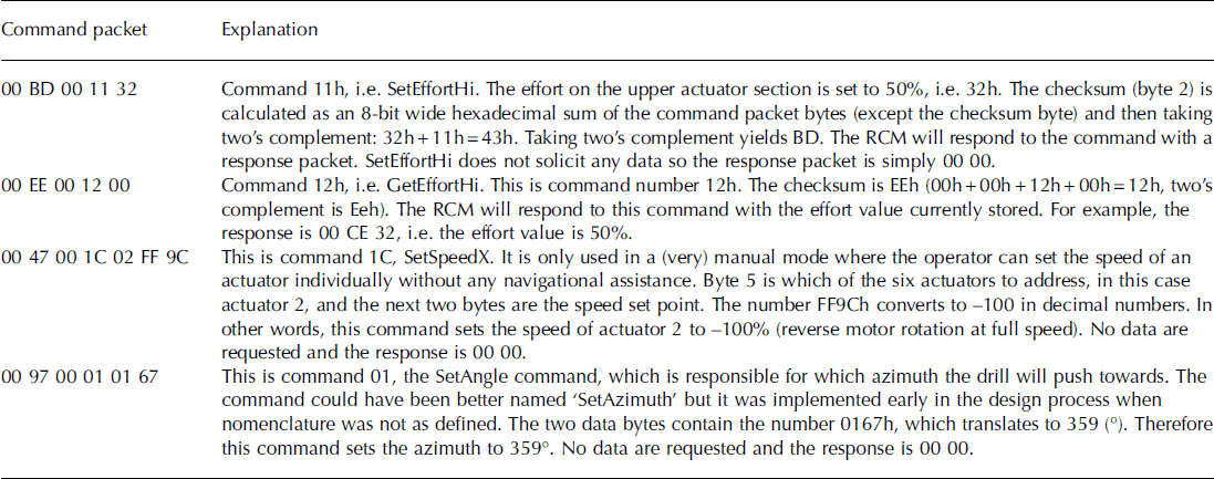
As mentioned, the replicate coring system makes use of a protocol to allow communication. It is through this protocol that angles, effort values, etc., are set. To do this, commands are sent to the RCM where they are error-checked and interpreted. The software is modular in its design, so each command is dispatched to the appropriate module where it is further interpreted and executed. Each command is sent to the RCM as part of a data packet. The packet includes a checksum and other redundant information present for error-checking. A command is passed on to a receiving software module only if the packet has passed error-checking. Beyond the checksum, a command is checked for range and other parameters depending on the command. For example, the SetEffortHi command, which sets the effort for the upper actuator section, might be checked for the range of the effort value, which should fall within 0–100%. Once the actuator software module receives the error-checked command it will process it and calculate the effort values for each of the upper actuator section actuators. For example, an effort value of 0% results in all actuator channels set to a retract speed and torque. It should be understood that 0% tells the software that the operator wants all arms retracted, thus all arms are energized in an inward direction. Conversely, a nonzero value results in the actuator arms moving outward to push at the wall at a commanded force proportional to the SetEffort value sent. In the event of a bogus command being received, the parser will ignore it and take no action. Thus the system depends on the surface computer to ‘double check’ whether a command is properly received. For this reason, each command usually has a ‘complementary’ command that reads back the value. For example, the command SetEffort has a complementary command called GetEffort. GetEffort should return whatever value was last commanded by SetEffort. If there is a difference, the command has not been received properly. The detection of such a difference has a manual component to it as the control room operator has before him or her (on the computer screen) both the parameters he/she has sent to the drill and those that the drill has received. The operator can therefore see any difference that may have occurred. In practice, over the course of drilling seasons, several such incidents were observed. However, no effort was made towards automating this part of the operation. Table 1 shows some of the commands. The commands follow this format: byte 1 is the thread ID and can have any value; byte 2 is a checksum; byte 3 is reserved for future use and is always zero (it was thought that more ID-related information might be required to accommodate multi-threading in the surface computer); byte 4 is the command ID (e.g. SetEffortHi is 11h, GetEffortHi is 12h); and bytes 5–12 are data bytes (some commands require several bytes to be sent to the RCM). Response packets follow this format: byte 1 is the thread ID (the RCM will send back the same ThreadID it received in the command packet it is responding to); byte 2 is the checksum; and bytes 3–10 are data bytes.
Examples of command packets
Process actuators
The main commands that the software actuator nodule receives are: SetEffort, SetAngle and SetRepStatus. SetEffort can be understood as meaning ‘how hard should the drill push?’. Set angle sets the angle (compass bearing) towards which the drill pushes. This angle is in degrees and is dependent of another command, SetAzimuth, which informs the drill how it is rotated relative to north–south–east–west. Combining this information allows the drill to always ‘know’ where a given magnetic heading is relative to the drill’s ‘clocking’ in the borehole.
Actuator processing is also responsible for reading LVDTs and setting the velocity profile used to ascertain the correct force on the actuators. The status register is used to communicate how the operator wishes to run the replicate coring system. It includes flags to set automatic mode (normal mode) or manual mode where each actuator can be set manually using separate SetEffort commands. It also communicates error flags that the RCM software can set if it detects errors of certain types. It is through the status register that the velocity profile, skew table and other control functions are enabled or disabled.
Surface PC-based software and GUI
Full control of the replicate coring drill is available to the user through two surface computers running National Instruments LabVIEW as a GUI. The specific replicate coring programs are add-ons to the previously run DISC programs and therefore maintain the same basic features, with one computer running the winch and one the drill sonde. Winch operations are virtually the same with or without replicate coring functionality, so almost all of the new code resides in the sonde program. All sensors and displays previously available in the DISC program are carried over into the replicate program.
The sonde program operates in conjunction with the ‘round-robin’ nature of the RCM software so that they are continuously communicating to transfer data and commands in both directions. ‘Get’ commands are continuously cycled through the GUI, meaning that it is always polling the RCM for sensor information and getting back the results. ‘Set’ commands are driven by an event queue such that whenever the user clicks a button to send a command to the drill (e.g. SetAngle), a command is sent directly to the RCM.
Standard replicate coring operations are able to occur completely in ‘auto’ mode. This mode is as described above where the primary inputs for the user are high effort, low effort and angle. Additionally, the software is able to run in ‘manual’ mode. This mode allows experienced users to directly control each individual actuator arm for certain advanced maneuvers and troubleshooting procedures.
Operation
The preceding sections have provided a description of the design and workings of the overall system. However, further insight into the general use of the system can be obtained through study of the procedure generally followed when creating a deviation from a parent borehole.
Descent
During the descent phase of the operation the drill is lowered through the borehole to the start depth, i.e. the depth at which the deviation is being created. At this depth the drill descent is stopped. During the entire descent, the replicate coring system is in one of two states (depending on the operator’s preference): off or retracted (i.e. a special ‘inert’ mode where the actuators are all completely withdrawn and held in that state with a small inwards force).
Setting the drill parameters
If no prior deviation drilling has been performed, the parent borehole is in an undisturbed state. At this point it may be necessary to use the drill as a ‘gauge’ to find the uphill side. Gauging for the uphill side is a relatively straightforward process and follows a set sequence. The replicate coring system is activated and set to a heading of 0° (due north). Once the actuators have seated onto the wall (when the LVDT read-outs indicate that the actuators are not moving further out, i.e. seated on the borehole wall), the drill inclination is measured with the inclinometer. The actuators are then all retracted. A next set point of 90° is sent to the drill and a new inclination is measured in a similar manner. This is repeated around the compass until the set point yielding the highest inclination is found. That inclination is entered into the driller’s log as the uphill side of the borehole. This procedure is needed only once per deviation, as on subsequent drill runs the recorded set point is sent to the drill. Since the recorded set point is relative to north, there is no need for any adjustment to account for drill rotation.
If the uphill set point is already determined, by following the above approach, the operator will enter the set point into the surface computer. Several other parameters will need to be set correctly, as described below.
The drill mode is the parameter that selects between side push and initial angle. Which particular mode is desirable depends on the drill configuration and how far progressed the deviation is (performing a deviation requires numerous trips such that the drill can be emptied of chips and reconfigured to suit the changing borehole geometry).
The effort on the upper and lower actuator sections (EfforHi and EffortLo) needs to be calculated beforehand by the lead engineer. This will be based on a model of the drill, taking into account the drill characteristics (length, weight, stiffness) and borehole inclination. The model calculates the points of contact with the borehole wall, drill flexure and force at the drill head. Margin is allowed to account for any modeling inaccuracy, particularly regarding the critical parameter of cutter force. The model accuracy was determined experimentally to be 20-30% on the cutter force parameter.
Duty cycle is used as one of the control parameters for the velocity profile and helps the system maintain the desired combined force of an actuator section. It was determined experimentally that values of 80-90% are successful in controlling the two forces of the actuator sections (Fa and Fb ).
The velocity profile period is set to 2 s. With a 90% duty cycle, this means that the actuators will travel outwards for 1.6s and inwards for 0.4 s.
Drilling
At this point the drill head is pressed against the uphill side of the borehole wall and drilling can be started. The pump and cutter motors are turned on. Since the drill may shift when the motors are started, a little time (∼30s) is allowed. When the operator is satisfied that the drill is running well, the winch will be started, thereby moving the drill in the borehole, and drilling begins. If broach cutters are used, the drill will move upwards, broaching as it goes. If rotating ‘milling’ cutters are used, the motion is downwards. Thus, the start depth is dependent on the type of cutter used.
Assuming broach cutters are used (most frequently broach cutters are used for the first part of a deviation and milling cutters later on), the winch is kept moving upwards until the end depth is reached. The difference between the start depth and the end depth is called the stroke length and is generally 15-20m depending on the maximum anticipated drill length. At the end depth the cutter is stopped, the actuators are retracted and the drill is lowered back down to the start depth for the next stroke.
As the above sequence is repeated, the borehole is enlarged in the direction of the uphill side and extra room is created to allow the drill to be turned away from the parent borehole.
Ascent
When the screen section (also known as the chips chamber) is full, or the deviation is enlarged enough to warrant a drill reconfiguration, the drill is returned to the surface. To do this, the actuators are retracted, the cutter and pump motors are shut off and the winch is commanded to wind the drill cable in. Once on the surface, the drill is readied for the next drill run.
Conclusion
This paper has shown that the replicate coring system spans several engineering disciplines: electrical, mechanical, software and, the most obvious, control. However, magnetic and inertial system members, such as the inclinometer, LVDTs and navigation sensor, also play important roles in the successful operation of the system. The amount of functionality and parts included in the system design may appear daunting; however, the modular design and use of modern miniaturization (surface mount parts, double-sided multilayer circuit boards, MEMS (MicroElectroMechanical Systems)) greatly eased the design process.
The concepts used in the electronic control system and indeed the entire replicate coring system are generally applicable and are therefore conceptually adaptable to other drill systems. There is a possibility that future deep ice-coring projects could benefit from the introduction of similar replicate coring systems adapted to the specific drill used. Proven performance at WAIS Divide showed five deviations completed in one season. If a second deep main borehole had been drilled to collect ice core in addition to that collected from the first bore, a commitment of three to five seasons would have been necessary. The replicate approach reduced this to one season, so by a conservative estimate two to four seasons of work were eliminated leading to cost savings.



