1. Introduction
Research on soft robotics manipulators has received much attention in the past decades, especially in medical applications, due to its advantageous features, such as safer interaction with humans, high adaptability, and affordability. Various designs have been proposed throughout the years for different applications, which usually consist of different segments that can be actuated by either variable-length tendons [Reference Calisti, Giorelli, Levy, Mazzolai, Hochner, Laschi and Dario1, Reference Ito, Homma and Rossiter2] or pressurized fluid [Reference Marchese and Rus3–Reference Bao, Chen, Zhang, Cai, Xu, Yang and Zhang5]. In this work, we focus on fiber-reinforced soft manipulators that are actuated by pressurized fluids, and in particular on tubular-shaped designs with three internal chambers, thus having the capability to control two degrees of freedom (DoFs).
The design of a tubular soft robotics manipulator with three internal chambers of actuation was first proposed by Suzumori et al. [Reference Suzumori, Iikura and Tanaka4]. This design was made with a rubber body capped at the end, wound with fiber, and controlled by a digital pressure regulator. By increasing the internal pressure in the chambers, the manipulator is able to move in three DoFs, which are pitch, yaw, and elongation. This design was later optimized in refs. [Reference Decroly, Mertens, Lambert and Delchambre6–Reference Franco, Ayatullah, Sugiharto, Garriga-Casanovas and Virdyawan9], by adding an inextensible central rod to limit its longitudinal elongation and allowing chamber deformation thus resulting in increased payload capabilities [Reference Garriga-Casanovas, Treratanakulchai, Franco, Zari, Ferrandy and Virdyawan10].
The significance of fiber reinforcement on fluidic actuators has been well studied, especially the helical-shaped winding, as it has been widely used due to its ease of manufacturing. Connolly et al. [Reference Connolly, Polygerinos, Walsh and Bertoldi11], for instance, have explored the effects of helical fiber winding, mainly with respect to the angle, on the motions of single-chamber soft actuators such as extension, radial expansion, and twisting. The study showed how the fiber winding can be tuned to produce a soft actuator with a specific range of motion. Finite element analysis (FEA) has been instrumental in the design of fiber-reinforced soft manipulators [Reference Decroly, Mertens, Lambert and Delchambre6, Reference Connolly, Polygerinos, Walsh and Bertoldi11–Reference Zhang and Oseyemi15]. However, due to the high deformation and non-linear material characteristic of soft manipulators, achieving numerical convergence and accuracy while maintaining low computational time is challenging. Consequently, most existing numerical models only deal with single-chamber manipulators with limited chamber deformation. A soft robotic manipulator with three chambers, required for bending in multiple directions, involves complex geometry and a high amount of non-linear surface contact that occurs inside the manipulator during pressurization, further worsening the simulation convergence.
To the author’s knowledge, no research has been published documenting how various fiber winding parameters would affect the bending motion of a tubular soft robotic manipulator with two actuated DoFs. In this paper, we investigate the effect of the helical fiber winding parameters, such as pitch and intersection position of the winding, on the bending motion of a tubular manipulator with three chambers. We also discuss the effect of other winding types on the bending motion. We achieve this by first developing a finite element simulation of the manipulator movement, which is then validated using experimental data.
The main contributions of the paper include the following: first, a procedure for developing a numerical simulation of three chambers manipulator to optimize its convergence and computation time; second, a study of helical fiber winding parameters to optimize the bending motion of a soft robotic manipulator with three internal chambers; third, a comparison of different winding shapes and their effect on the three chambers manipulator that could serve as alternatives to the helical shape.
The rest of the paper is organized as follows: Section 2 details the finite element modeling of the manipulator. Section 3 presents the manufacturing process of the manipulator, the experimental setup, and the comparative analysis of simulations and experiments. The results are presented in Section 4. Lastly, concluding remarks and future works are described in Section 5.
2. Design and finite element modeling
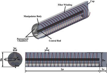
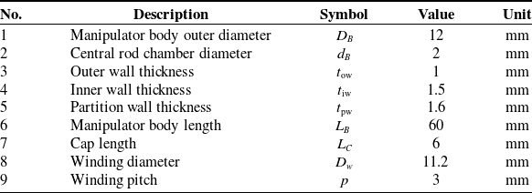
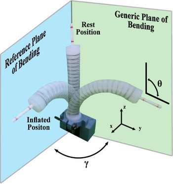
The soft manipulator was designed according to refs. [Reference Garriga-Casanovas, Collison and Rodriguez y Baena7, Reference Garriga-Casanovas, Treratanakulchai, Franco, Zari, Ferrandy and Virdyawan10] to maximize its force while maintaining a small diameter. The design is tubular, with three internal chambers spaced at 120°, allowing bending on any plane. An inextensible cable sleeve is placed at the center of the section and serves to prevent elongation when the chambers are pressurized, thus increasing the maximum bending and force at any given pressure. Additionally, a thread is wound around the external cylindrical surface in both directions (i.e., clockwise and counterclockwise), to prevent radial expansion without producing twisting effects [Reference Suzumori16]. In the initial design, we chose the widely used helical windings with a constant pitch of 3 mm, but in some of the following sections, the winding specifications (e.g., types, pitch, intersection position of the winding) have been varied. The outer diameter of the manipulator is 12 mm, and the total length is 66 mm, which consists of a 6 mm end cap and a 60 mm body section with internal chambers. Figure 1 and Table I summarize the key design parameters of the manipulator while Fig. 2 shows the manipulator’s DoFs.
The design of the manipulator.

Manipulator component specifications.

Two DOFs of the manipulator.

The finite element models were developed in Abaqus/Standard (Simulia™; Dassault Systemes, Velizy-Villacoublay, France). Their purpose is to predict the deformation and bending angle of the manipulator when it is pressurized on each of the different chambers.
The model of the manipulator consists of three main parts: the main body, the fiber winding, and the central rod. All the parts were modeled as 3D Solid Deformable, while the fiber winding was modeled as 3D Wire Deformable. The helical geometry of the winding was created using a modified python script from ref. [17], which receives inputs of winding pitch, winding length, and winding offset to calculate the helical geometry. As the fiber is wound in both directions, a second part mirroring the original winding was also included.
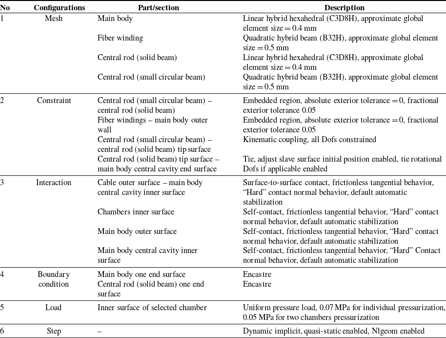
The central rod is characterized by high longitudinal stiffness but low bending stiffness. This has been modeled by embedding a small diameter circular beam with high stiffness inside of a solid beam with low bending stiffness in an assembly and adding corresponding constraints. This was necessary because, unlike other work such as ref. [Reference Bao, Chen, Zhang, Cai, Xu, Yang and Zhang5], the internal chambers in our prototype are highly deformable. Thus, reducing the central rod diameter to limit the bending stiffness might affect the manipulator’s inner deformation. The main limitation of this modeling strategy lies in the solid beam that must be modeled as a non-hollow tube, unlike a cable sleeve. In this work, this limitation was neglected, seeing the potential reduction of computational time and assuming that the impact is insignificant.
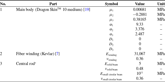
The material of the main body is Dragon Skin™ 10 Medium (Smooth-On, Inc., Pennsylvania, USA), and it was modeled using incompressible isotropic hyperelastic material with 3rd-order Ogden constitutive law [Reference Ogden18]. On the other hand, the fiber winding and the central rod were modeled as an isotropic elastic material. The complete list of material coefficients used in the model is shown in Table II.
Material coefficients for the model.

*Central rod material coefficients were assumed rather than obtained through experiments due to the difficulties in testing the unique characteristics of the material (i.e., high longitudinal stiffness but low bending stiffness). The values used in this work were chosen to achieve a negligible effect on the simulation’s bending stiffness, while still preventing manipulator’s elongation.
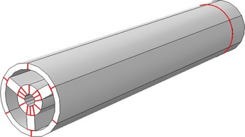
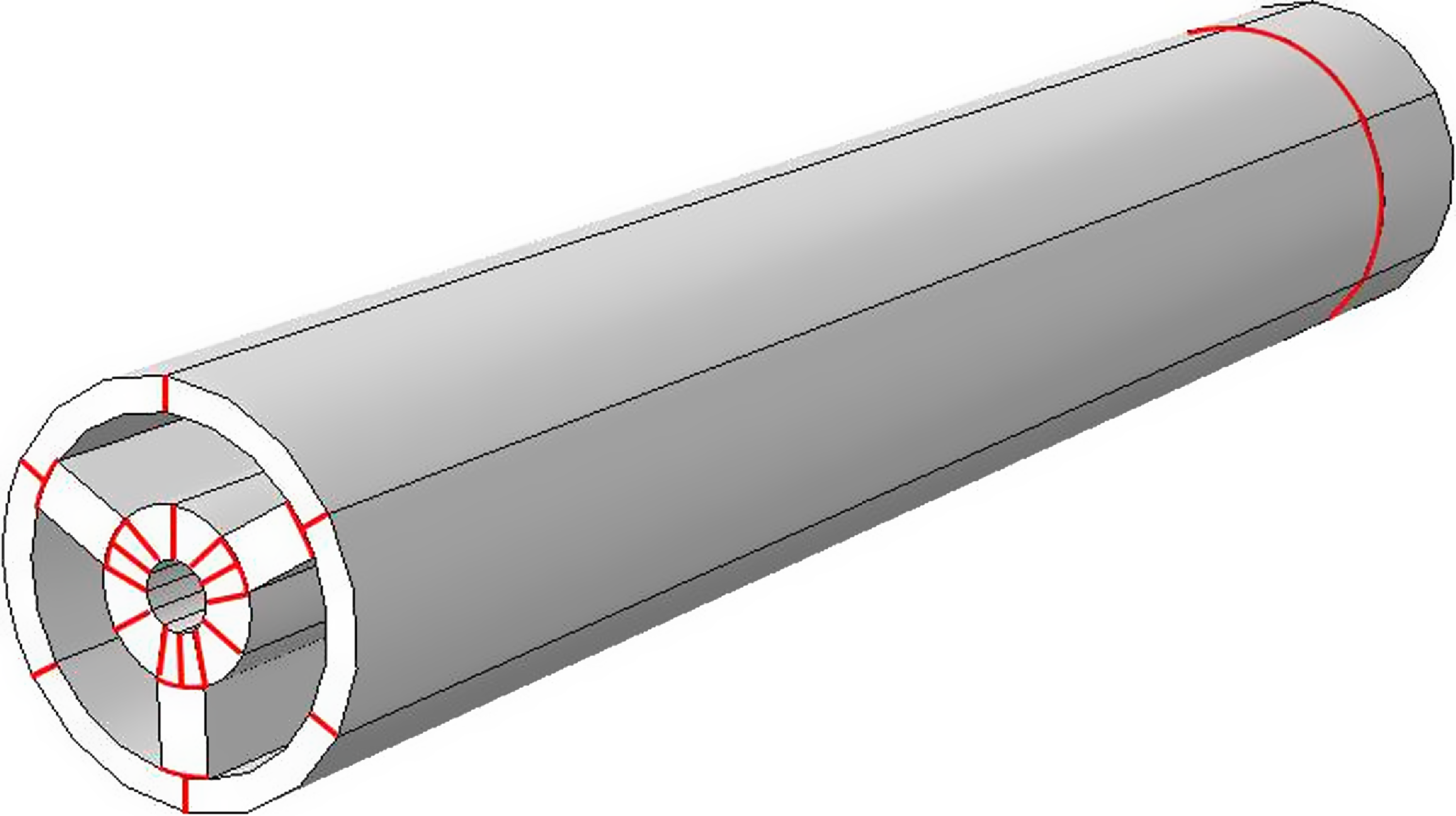
The main body and the central rod were meshed with hexahedral element type to prevent element distortion [Reference Gent20]. The geometry order of the element was set as linear instead of quadratic as this had shown to help the convergence of the simulation without significantly affecting the accuracy of the results. The formulation of the elements was set as a hybrid to allow the inclusion of non-linear effects (C3D8H). The winding and the circular beam embedded in the central rod were meshed with quadratic order and hybrid formulation elements (B32H). Soft robotic manipulator simulation, especially manipulator with three chambers, involves high deformation; therefore, minimizing distortions is crucial to the convergence of the simulation. To further improve the mesh quality in Abaqus, the main body was partitioned into various symmetrical parts (see Fig. 3).
Model partition pattern. Red lines show where each part of the model is separated using Abaqus cell partition feature.
The next step in developing the simulation was to create an assembly by assigning all the parts and then applying the simulation interactions, constraints, boundary conditions, load, and simulation steps. The first two constraints were applied to create the central rod behavior: first, the embedded region with the circular beam as the embedded object and the solid beam as the host region; second, coupling with the tip of the circular beam as the control point and the end surface of the solid beam as the control surface. The third and fourth constraints tie the tip of the central rod and the winding to the main body of the manipulator. The interactions assigned were self-contact of each internal chamber, self-contact of the outer surface of the main body, and surface-to-surface contact with the outer surface of the central rod as the master surface and the internal center chamber of the main body as the slave surface. All interactions were modeled as frictionless tangential contact and “hard contact” normal behavior. An encastre boundary condition was applied at one end of the manipulator, and a uniform load due to the internal pressure was imposed in one of the internal chambers and a ramp amplitude. Finally, the Dynamic Implicit step with Quasi-static application and Nlgeom setting enabled was employed. The Standard General step could also be used, but we have found that the Dynamic Implicit step resulted in better simulation convergence while keeping the inertia effect negligible.
Some works have shown that the inclusion of gravity might affect the simulation result [Reference Xavier, Fleming and Yong21], and in our testing, gravity did contribute to altering the manipulator’s bending angle to a certain extent. However in this work, we neglected the effect of gravity considering the low mass of the prototype, and the computation cost with gravity increased significantly. In addition, the effect of gravity is not relevant to the study of the effect of fiber windings since the soft robotic manipulator typically needs to be able to operate at different orientations and there is no predefined orientation.
The bending angle (θ) was calculated by using the coordinates of two nodes at the end of the manipulator. The manipulator displayed a tendency to skew toward one side at higher pressures, thus changing the bending plane as it is being pressurized. To solve this issue, the bending plane orientation angle (γ) was calculated using the following trigonometric equation:
 \begin{equation}\gamma =\text{atan}2\!\left(\frac{{\Delta} y_{0}}{{\Delta} z_{0}}\right)\end{equation}
where
 ${\Delta} y_{0}$
and
 ${\Delta} z_{0}$
are the displacement of the reference node at the tip of the manipulator for the y-axis and z-axis, respectively. The bending angle (θ) with a changing bending plane orientation (γ) can then be calculated with the following equations:
 \begin{equation}z_{f_{1}}^{\prime}=z_{{f_{1}}}\cos\! \left(\gamma \right)+y_{{f_{1}}}\sin\! (\gamma )\end{equation}
 \begin{equation}z_{f_{2}}^{\prime}=z_{{f_{2}}}\cos\! \left(\gamma \right)+y_{{f_{2}}}\sin\! (\gamma )\end{equation}
 \begin{equation}\theta =\tan ^{-1}\! \left(\frac{z_{f_{1}}^{\prime}-z_{f_{2}}^{\prime}}{x_{{f_{1}}}-x_{{f_{2}}}}\right)\end{equation}
where
 $x_{{f_{1,2}}}$
,
 $y_{{f_{1,2}}}$
, and
 $z_{{f_{1,2}}}$
are the coordinates of the reference node at the end of the manipulator on all axes, and
 $z_{f_{1,2}}^{\prime}$
are the coordinates of the reference node on the z-axis after matrix transformation. The complete list of simulation configurations used in the model is shown in Table III.
Simulation configurations.

3. Fiber winding variations results
The numerical simulation was used to investigate the effect of the fiber winding parameters on the bending motion of a soft robotic manipulator with three internal chambers. It was also used to estimate and compare the stiffness of each chamber when different fiber winding shapes were used. The numerical simulation allowed for a more straightforward and faster investigation compared to the manufacturing and experimental methods. A wider range of fiber winding variations that might be challenging to be fabricated could also be tested.
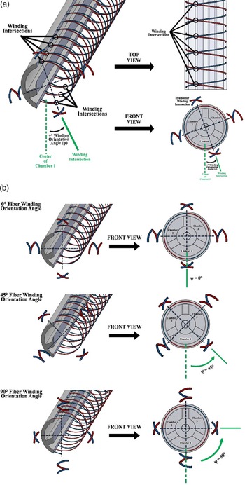
Winding orientation angle (
 $\psi$
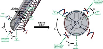
) is defined as the angular distance between the center of the first chamber and the intersection of the two helical windings. This should not be confused with the term winding angle which is often used in other works, as the winding orientation angle is an independent variable that does not effect the winding pitch. In this section, we completed simulations with helical windings that have a constant pitch of 3 mm, but with a range of different fiber winding orientation angles: 0°, 30°, 45°, 60°, and 90°. Pressure will be supplied to each of the three chambers for every winding orientation angle variations; thus, the bending angle will also be measured on three different directions that are spaced at 120° relative to each other. Our definition and convention of fiber winding orientation angle are further explained in Fig. 4. The simulation output is the comparison of the bending angle (θ) in relationship with each chamber’s internal pressure.
Fiber winding orientation angle: (a) definition and convention; (b) examples. In all of the figures, the red color depicts counterclockwise winding, while the blue color depicts clockwise winding. The intersection of both windings is marked with black circles. Winding orientation angles are the angular distance measured from the center of chamber 1 (depicted as green dotted lines) to the winding intersection.

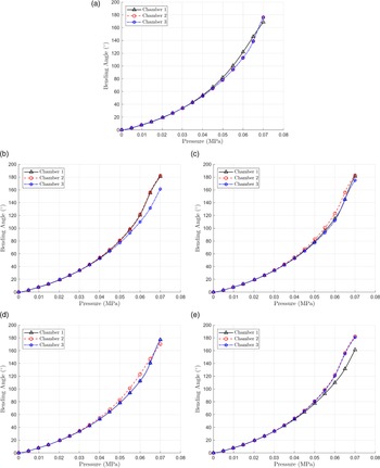
The output data obtained from simulations are shown in Fig. 5. The simulation was able to converge up to the given pressure of 0.07 MPa with the highest bending angle of 180°. The results showed that the fiber winding angle does affect the stiffness of each chamber at higher pressure. For helical windings with a constant pitch, the closer the center of a particular chamber is to the intersection of the windings, the lower the bending stiffness of that chamber is when pressurized. Therefore, the highest bending stiffness is achieved for the first chamber, when the fiber winding orientation (
 $\psi$
) is 90° and the smallest bending stiffness is at 0°, since in these configurations, the winding intersection will be the furthest from the center of the first chamber at 90° and the closest at 0°. The cause of this behavior can be related to the distribution of the windings, as the density of different fiber winding orientation angles is the same. One possible reason for this is that when the fiber winding orientation angle is set at 0°, the distribution of windings allows the pressurized chamber’s outer wall to balloon symmetrically. This leads to a greater magnitude of force vectors resultant, which in turn produces greater elongation of the outer wall and a higher bending angle. This relationship can be explained with the following equation:
 \begin{equation}R_{n}=\frac{\psi _{n}^{\prime}}{180-\psi _{n}^{\prime}}\end{equation}
where
 $R_{n}$
is a variable directly proportional to the bending stiffness of particular chamber n, and
 $\psi _{n}^{\prime}$
is the angular distance between the center of the particular chamber n to the closest intersection of the two helical windings (shown in Fig. 6). With this relationship, the bending stiffness of a particular chamber n is at its maximum when
 $R_{n}=1$
(
 $\psi _{n}^{\prime}=90^{\circ}$
) and the minimum corresponds to
 $R_{n}=0$
(
 $\psi _{n}^{\prime}=0^{\circ}$
).
Bending angle vs. pressure simulation of each chamber in different fiber winding orientation angles: (a) 0°; (b) 30°; (c) 45°; (d) 60°; (e) 90°.

The angular distance between the center of the particular chamber n to the closest intersection of the two helical windings (
 $\psi _{n}^{\prime}$
).

The difference in each chamber is significant only at higher bending angles (i.e., around 70° for all tested fiber orientation angles); thus, a manipulator designed to operate at lower pressure might neglect this difference. A theoretical optimized value of
 $\psi _{n}^{\prime}$
, would be when the resulting
 $R_{n}$
of each chamber is approximately the same. As the section of the manipulator with three chambers is symmetrical, the optimized value can be calculated by dividing the problem into two different cases:
 $0^{\circ}\leq \psi _{1}^{\prime}\leq 30^{\circ}$
and
 $30^{\circ}\lt \psi _{1}^{\prime}\leq 60^{\circ}$
. We would also be able to define the relation between
 $\psi _{1}^{\prime}$
with
 $\psi _{2}^{\prime}$
and
 $\psi _{3}^{\prime}$
as:
 \begin{equation}\psi _{2}^{\prime}=\begin{cases} \psi _{1}^{\prime}+60^{\circ},&\text{for }0^{\circ}\leq \psi _{1}^{\prime}\leq 30^{\circ}\\ 120^{\circ}-\psi _{1}^{\prime},&\text{for }30^{\circ}\lt \psi _{1}^{\prime}\leq 60^{\circ} \end{cases}\end{equation}
 \begin{equation}\psi _{3}^{\prime}=60^{\circ} -\psi _{1}^{\prime},\text{ for }0^{\circ}\leq \psi _{1}^{\prime}\leq 60^{\circ}\end{equation}
With these in mind, we would have
 \begin{equation}{R}_{1}=\frac{\psi _{1}^{\prime}}{180^{\circ}-\psi _{1}^{\prime}},\text{ for }0^{\circ}\leq \psi _{1}^{\prime}\leq 60^{\circ}\end{equation}
 \begin{equation}{R}_{2}=\begin{cases} \dfrac{\psi _{1}^{\prime}+60^{\circ}}{120^{\circ}-\psi _{1}^{\prime}},\text{ for }0^{\circ}\leq \psi _{1}^{\prime}\leq 30^{\circ}\\[9pt] \dfrac{120^{\circ}-\psi _{1}^{\prime}}{60^{\circ}+\psi _{1}^{\prime}},\text{ for }30^{\circ}\lt \psi _{1}^{\prime}\leq 60^{\circ} \end{cases}\end{equation}
 \begin{equation}{R}_{3}=\frac{60^{\circ} -\psi _{1}^{\prime}}{120+\psi _{1}^{\prime}},\text{ for }0^{\circ}\leq \psi _{1}^{\prime}\leq 60^{\circ}\end{equation}
and to obtain the optimized angle (
 $\psi _{\text{optimal}}$
), the difference between each
 $R_{n}$
(Δ1 = |R
2 −R
1| + |R
3 −R
1|,
 ${\Delta} 2=|\mathit{R}1-\mathit{R}2| + |\mathit{R}3-\mathit{R}2|$
, Δ3 = |R
1 −R
3| + |R
2 −R
3|) should be at a minimum. This results in three possible
 ${\psi _{1}^{\prime}}_{\text{optimal}}$
, which are first,
 ${\psi _{1}^{\prime}}_{\text{optimal}}=0^{\circ}$
, which would result in two chambers having the same stiffness but one chamber having a smaller stiffness (R
1 = 0, R
2
= R
3 = 0.5); second,
 ${\psi _{1}^{\prime}}_{\text{optimal}}=30^{\circ}$
, which would result in two chambers having the same stiffness but one chamber having a larger stiffness (R
1
= R
3 = 0.2, R
2 = 1); or third,
 ${\psi _{1}^{\prime}}_{\text{optimal}}=12^{\circ}$
, which would result in all three chambers having relatively small differences in stiffness (R
1 = 0.07, R
2 = 0.67, R
3 = 0.37). The second option is inferior to the first option in terms of stiffness, thus the preferred options are
 ${\psi _{1}^{\prime}}_{\text{optimal}}=0^{\circ}$
(
 ${\psi _{2}^{\prime}}_{\text{optimal}}={\psi _{3}^{\prime}}_{\text{optimal}}=60^{\circ}$
) and
 ${\psi _{1}^{\prime}}_{\text{optimal}}=12^{\circ}$
(
 ${\psi _{2}^{\prime}}_{\text{optimal}}=72^{\circ}$
and
 ${\psi _{3}^{\prime}}_{\text{optimal}}=48^{\circ}$
).
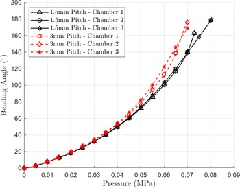
Another possible alternative is to reduce the pitch of the helical windings, which would also increase the overall bending stiffness of the manipulator. Through numerical simulations of various pitch variations, we have found that with the increase of overall bending stiffness, the difference between chambers is reduced, as shown in Fig. 7. This alternative might serve as a reasonable tradeoff for cases that prioritize the similarity among the chambers rather than higher bending angles.
Bending angle vs. pressure simulation of each chamber in different pitch variations.

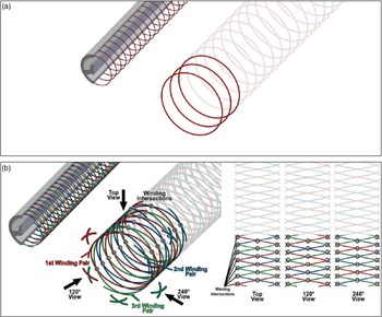
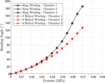
Another alternative is to use other types of winding instead of helical, such as ring windings or six helical windings, shown in Fig. 8. The ring windings do not have the asymmetric nature of double helical windings, but the corresponding manufacturing process is much more complex. Six helical windings that include three pairs of double helical windings spaced at 120° would prevent asymmetry but would also complicate the manufacturing process, especially in a miniaturized manipulator, and they would increase the stiffness significantly. Both alternatives were also tested through numerical simulations, resulting in the same bending stiffness of each chamber, as shown in Fig. 9.
Other types of winding: (a) ring winding; (b) six helical winding. Figure (b) includes a two-dimensional view of the six helical windings from the top, at 120°, and 240°. These views showcase the symmetrical shape of the six helical windings in different sections that cover each of the chambers.

Bending angle vs. pressure simulation of each chamber in different winding types.

4. Experimental validation
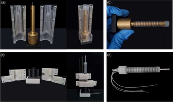
The prototype was manufactured using a similar method described in [Reference Virdyawan, Ayatullah, Sugiharto, Franco, Garriga-Casanovas, Mahyuddin, Rodriguez y Baena and Indrawanto22], with a four-part mold comprised of a two-part outer mold, an inner mold, and a base mold (see Fig. 10a) and another set of molds that accommodate the routing of the silicone tubes and the cable sleeve (see Fig. 10b). In contrast to the approach in [Reference Virdyawan, Ayatullah, Sugiharto, Franco, Garriga-Casanovas, Mahyuddin, Rodriguez y Baena and Indrawanto22], the two-part outer mold used in this work features grooves on its inner surface to create a path on the prototype. Using this path as a guide, an inextensible thread was then wound by hand around the outer face of the prototype (see Fig. 10c), to produce a perfect helical winding in both directions with a regular pitch and constant position of winding intersections (see Fig. 10d). The prototype has the same dimension specifications and materials as the finite element model developed in Section 2 (summarized in Fig. 1, Table I, and Table II). The central rod used was a hollow braided cable sleeve that was fixed at both ends of the prototypes during casting.
(a) Four-part mold set; (b) fiber winding process; (c) final sealing mold set; (d) final prototype.

An experiment was conducted to measure the bending angle of the prototype, and the data were used to validate the finite element model. A simple pneumatic actuation system and an experimental setup were developed. The actuation system consists of a pressure regulator, needle valves, pressure gauges, and exhaust orifices, as depicted in Fig. 11a. The pressure regulator was used to supply a constant air pressure to the rest of the system, while the needle valve allows manual airflow adjustment. An exhaust orifice and a pressure gauge were installed in parallel to the output connector, so that the output pressure can be regulated to the prescribed value by adjusting the airflow through the needle valve and reading the output pressure from the pressure gauge [Reference Virdyawan, Ayatullah, Sugiharto, Franco, Garriga-Casanovas, Mahyuddin, Rodriguez y Baena and Indrawanto22]. In this work, we used digital pressure gauges (PSAN-01CA-RC1/8, Autonics Sensors & Controllers, South Korea) with a display range of 0 to 0.1 MPa and a resolution of 0.001 MPa.
(a) Pneumatic actuation system; (b) experimental setup.

For the experiment setup, a clamp was used to fix the bottom end of the manipulator vertically while allowing the movement of the manipulator on three different axes. This configuration replicated the boundary conditions of the numerical simulation. Two markers were added at the tip of the manipulator, and three digital cameras (GoPro Hero5, GoPro, Inc., California, USA) were positioned at the platform’s front, side, and top (shown in Fig. 11b). The front and side cameras were used to measure the bending angle (θ), while front and top cameras were used to measure the orientation (γ) of the bending plane. Both camera pairs had been previously stereo-calibrated using image pairs of a checkerboard. A triangulation algorithm was used to track both of the marker coordinates in three axes, which were later used to calculate the bending plane orientation angle (γ) and the bending angle (θ) using Eq. (1) and Eq. (4), respectively.
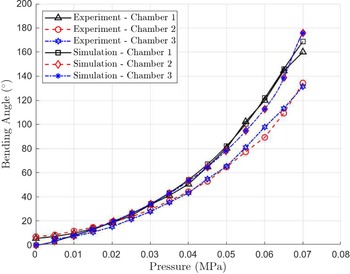
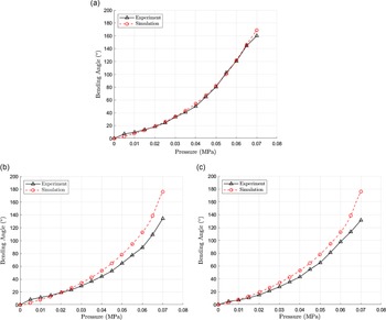
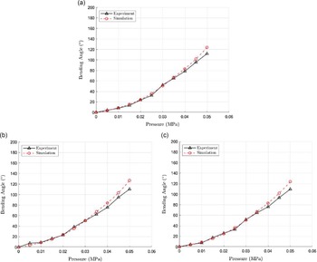
Using this experimental setup, the relationship between bending angle (θ) and internal pressure was investigated. The experiment was done by increasing the pressure of each chamber between 0.005 MPa and 0.07 MPa with 0.005 MPa increments. The bending angle (θ) was measured with respect to the z-axis. The θ-pressure curve was compared to the simulation results from Section 2, by increasing the internal pressure from 0.001 MPa up to 0.07 MPa. Both the experiment prototype and numerical model have a 0° winding orientation angle. The comparison between the experimental and numerical simulation is shown in Figs. 12 and 13.
Experiment and simulation – bending angle comparison.

Experiment and simulations – bending angle comparison: (a) chamber 1; (b) chamber 2; (c) chamber 3.

The finite element model was able to replicate the relative characteristics of each chamber well, where chamber 1 had the least stiffness, while chambers 2 and 3 both had similar but higher stiffness compared to chamber 1. Looking at the accuracy, the simulation performed well in replicating the bending slope of chamber 1, but unfortunately did not perform as well with chamber 2 and chamber 3, especially during high pressurization. In both chambers 2 and 3, the simulation tended to overestimate the bending angle, with the highest error occurring at 0.07 MPa, where the error reached about 20°.
These differences were likely attributed to manufacturing errors that resulted in imperfections, including non-uniform increased wall thickness along the chambers. Furthermore, in the pressurization simulation of chambers 2 and 3, we observed a noticeable sudden increase in the bending angle after reaching 0.06 MPa. Upon further inspection, this increase was found to be caused by a sudden buckling of the partition wall. We believe that this buckling occurred at higher pressure in the experiment due to the prototype’s imperfection, which further increased the bending angle difference at higher pressures. Additionally, the numerical model was simplified to exclude simulating complex phenomena, such as internal friction, in order to improve simulation efficiency. Nevertheless, the comparison still demonstrated the model’s ability to capture the relative difference in stiffness of each chamber, which can mainly be attributed to the asymmetric nature of the double helical windings.
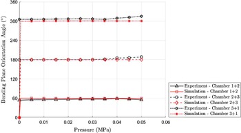
To further prove our validation, we conducted additional tests and compared the actuations of two chambers in the experiment. The comparison explored the relationship between bending angle (θ) and internal pressure, as well as the relationship between bending plane orientation angle (γ) and internal pressure. In this experiment, we subjected three-chamber combinations to increasing pressure values ranging from 0 to 0.05 MPa, with increments of 0.005 MPa. The combinations included Chamber 1 + Chamber 2, Chamber 2 + Chamber 3, and Chamber 3 + Chamber 1. The comparison between the experimental and numerical simulation results is presented in Fig. 14 for the bending plane orientation angle (γ) and Fig. 15 for the bending angle (θ).
Experiment and simulations – bending plane orientation angle comparison: (a) chamber 1 + 2; (b) chamber 2 + 3; (c) chamber 3 + 1.

Experiment and simulations – bending angle comparison: (a) chamber 1 + 2; (b) chamber 2 + 3; (c) chamber 3 + 1.

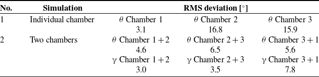
The results demonstrate that the model accurately captured the movement behavior of the manipulator when pressurized in different chamber combinations. The bending plane orientation angle (γ) value closely matched the experimental values in each combination, which were 60°, 180°, and 300°, respectively. Regarding the simulation bending angle (θ), although it reasonably replicated the slope, some overestimations were observed especially in higher pressure, which we believe can be mostly attributed to manufacturing imperfections and simplifications made in the simulation. The root mean square deviation for all the comparisons between the simulation and experiment are presented in Table IV.
RMS deviation comparison.

Despite the acknowledged limitations, the finite element model employed in this study demonstrated relatively good convergence, accompanied by satisfactory computational time and accuracy, especially when considering the substantial internal deformations within the design. We are confident that these model configurations can be successfully replicated for other soft manipulator designs, regardless of their DoFs, scales, or geometries. This approach holds particular significance for modeling more intricate designs, such as those incorporating an inextensible central rod or featuring deformable chambers. Moreover, certain simplifications employed can be disregarded for simpler designs, like those with simpler geometry (e.g., three tubes that are bundled together), non-deformable chambers, or a smaller number of chambers. By selectively omitting these simplifications, higher accuracy can be achieved without significant compromises in terms of convergence and computational time.
5. Conclusions
In this work, we presented the results of an FEA study for a tubular soft robotic manipulator with two actuated DoFs. This was employed to investigate the effect of helical fiber winding parameters, such as pitch and orientation, on the bending deformation of a tubular manipulator with three internal chambers. Finally, we compared the simulation results with extensive experiments.
The results of the simulations revealed that the fiber winding orientation affects each chamber’s bending stiffness at higher bending angles. We concluded that for helical winding with a constant pitch, the closer the center of a chamber is to the intersection of the windings (
 $\psi^{\prime}_n$
), the lower the bending stiffness of the particular chamber is. Due to the nature of double helical windings, it is impossible to set the fiber winding orientation angle (
 $\psi$
) on a certain value to achieve identical stiffness in all chambers. However, theoretically, the most optimal fiber orientations to achieve the closest stiffness for each chamber are 0° and 12°. We also proposed other ways to reduce the difference in bending stiffness among the chambers. The first alternative is to reduce the pitch of the helical windings, which would increase the bending stiffness but might serve as a reasonable tradeoff for cases that prioritize the similarity between chambers. Another alternative is to use other types of windings instead of helical, such as ring winding or six helical winding, which would avoid asymmetry at the cost of a more complex manufacturing process.
Comparing the finite element simulations with experimental data revealed that the model reasonably captured the bending characteristics of the manipulator, both during individual chamber pressurization and two chambers pressurization. However, it was observed that at higher bending angles, the estimation tended to be less accurate. We believe that these deviations were primarily caused by the non-uniform wall thickness of the prototype and the simplifications introduced in the numerical model, such as neglecting internal friction. Despite these limitations, the FEA model used in this work demonstrated relatively good convergence, reasonable computational time, and reasonably accurate results, considering the high inner deformation of the design. We are confident that these model configurations can also be replicated for other two DoFs manipulator designs with different scales or even different geometries. This approach would be particularly useful for modeling designs that employ an inextensible central rod or have deformable chambers, and expected to perform better on simpler designs, such as those with non-deformable chambers or smaller number chambers.
Author contributions
Conceptualization: VV, AGC, and SM; Methodology: VF, VV, SM, AGC, I, FF, AS, AIM, and EF; Formal analysis and investigation: VF, VV, and AGC; Writing – original draft preparation: VF; Writing – review and editing: VF, VV, AGC, and EF; Funding acquisition: FRYB and I; Resources: FRYB, I, and AIM; Supervision: SM, VV, AGC, FRYB, I, AIM, and FF. All authors commented on previous versions of the manuscript. All authors read and approved the final manuscript.
Financial support
This work was supported by a Newton Fund Institutional Links grant, ID 623531377, under the Newton Fund Indonesia partnership. The grant is funded by the UK Department for Business, Energy and Industrial Strategy and Directorate of Resources Affairs Directorate General of Higher Education, Ministry of Education, Culture, Research and Technology, Republic of Indonesia, contract no: 341/E4.1/AK.04.PT/2021 and 083/E5/PG.02.00.PT/2022, and delivered by the British Council.
Competing interests
The authors declare no competing interests exist.
Ethical approval
Not applicable.