1. Introduction
Vortex-induced vibration (VIV) of flexibly mounted cylinders placed in uniform flow has been studied extensively for cylinders free to oscillate in the transverse (cross-flow – CF) direction (Bearman Reference Bearman1984; Sarpkaya Reference Sarpkaya2004; Williamson & Govardhan Reference Williamson and Govardhan2004), in the streamwise (inline – IL) direction (Cagney & Balabani Reference Cagney and Balabani2014; Gurian, Currier & Modarres-Sadeghi Reference Gurian, Currier and Modarres-Sadeghi2019) or in both the CF and IL directions (Jauvtis & Williamson Reference Jauvtis and Williamson2004; Dahl, Hover & Triantafyllou Reference Dahl, Hover and Triantafyllou2006; Dahl et al. Reference Dahl, Hover, Triantafyllou, Dong and Karniadakis2007). In many real-world applications, such as mooring lines for floating offshore structures and marine risers, however, VIV is observed in long flexible structures. Experimental (Chaplin et al. Reference Chaplin, Bearman, Huarte and Pattenden2005; Trim et al. Reference Trim, Braaten, Lie and Tognarelli2005; Vandiver et al. Reference Vandiver, Marcollo, Swithenbank and Jhingran2005; Lie & Kaasen Reference Lie and Kaasen2006; Huera-Huarte & Bearman Reference Huera-Huarte and Bearman2009; Seyed-Aghazadeh & Modarres-Sadeghi Reference Seyed-Aghazadeh and Modarres-Sadeghi2016; Seyed-Aghazadeh, Edraki & Modarres-Sadeghi Reference Seyed-Aghazadeh, Edraki and Modarres-Sadeghi2019) and numerical (Evangelinos, Lucor & Karniadakis Reference Evangelinos, Lucor and Karniadakis2000; Bourguet, Karniadakis & Triantafyllou Reference Bourguet, Karniadakis and Triantafyllou2011a; Bourguet et al. Reference Bourguet, Modarres-Sadeghi, Karniadakis and Triantafyllou2011b; Bourguet, Karniadakis & Triantafyllou Reference Bourguet, Karniadakis and Triantafyllou2013; Zanganeh & Srinil Reference Zanganeh and Srinil2016) studies have well documented the VIV response of a flexible cylinder, placed perpendicular to the flow. Excitation of mono- and multi-frequency modes and transition from low mode to high mode excitations have been observed in the VIV response of such flexible cylinders.
Nevertheless, there are several applications, such as offshore risers that are often deployed as the catenary type with a curved shape, in which the cylinder is not placed perfectly perpendicular to the direction of the incoming flow. Studies on flow-induced vibration of cylinders that make a fixed angle with respect to the incoming flow, i.e. an inclined cylinder (Jain & Modarres-Sadeghi Reference Jain and Modarres-Sadeghi2013; Bourguet & Triantafyllou Reference Bourguet and Triantafyllou2015; Han et al. Reference Han, Ma, Xu, Lu and Cheng2017; Seyed-Aghazadeh & Modarres-Sadeghi Reference Seyed-Aghazadeh and Modarres-Sadeghi2018), and those where the angle that the cylinder makes with the incoming flow varies continuously along its length, i.e. a curved cylinder (Assi et al. Reference Assi, Srinil, Freire and Korkischko2014; Seyed-Aghazadeh, Budz & Modarres-Sadeghi Reference Seyed-Aghazadeh, Budz and Modarres-Sadeghi2015a), have helped to elucidate the effects of passive asymmetry introduced into the system through the structure on its VIV response. In the case of a curved cylinder, forming a quarter of a ring, the cylinder can be placed in two different orientations: the convex orientation in which the upper end of the cylinder sees the flow first and the concave orientation in which the lower end of the cylinder sees the flow first. The flow behaviour in the wake of a fixed curved cylinder placed in flow has been studied through numerical simulations (Miliou, Sherwin & Graham Reference Miliou, Sherwin and Graham2003; De Vecchi, Sherwin & Graham Reference De Vecchi, Sherwin and Graham2009; Gallardo, Andersson & Pettersen Reference Gallardo, Andersson and Pettersen2014; Xu & Cater Reference Xu and Cater2017) and experiments (Takamoto & Izumi Reference Takamoto and Izumi1981), and the fully three-dimensional wake dynamics has been observed for both configurations. In the case of oscillating cylinders, however, the wake characteristics become quite different from those of the stationary cylinders. De Vecchi et al. (Reference De Vecchi, Sherwin and Graham2009) conducted a numerical study on flow past a rigid curved cylinder in the convex orientation and forced to oscillate in the CF direction at a Reynolds number of  $Re= 100$. The cylinder used in their simulations featured a long horizontal extension attached to the lower part of the cylinder. This part of the cylinder was parallel to the flow and acted as a slender body, rather than a bluff body, and therefore experienced drag-type forces. The vortex columns in the wake of the cylinder were bent following the curvature of the cylinder, contrary to the case of the stationary cylinder in which the vortex columns remained straight (De Vecchi et al. Reference De Vecchi, Sherwin and Graham2009). Vortex dislocations were observed for the convex orientation at mid-span of the curved cylinder as a consequence of different shedding frequencies at the lower and upper parts of the cylinder. Zhu et al. (Reference Zhu, Wang, Bao, Zhou, Ping, Han and Sherwin2019b) have observed a bi-stable flow feature for flow past a curved cylinder, characterized by intermittent switching between the vortex shedding and vortex reattachment. They have mentioned that the perturbation that triggers this unstable shedding mode is likely to be related to the fluctuation in the axial flow component. Later, experiments on VIV of a curved cylinder (a quarter of a ring), with no extension added to either end, and free to oscillate in the CF direction were conducted (Seyed-Aghazadeh et al. Reference Seyed-Aghazadeh, Budz and Modarres-Sadeghi2015a). The amplitudes of oscillations in both the convex and the concave configurations were found to decrease compared with a vertical cylinder. Higher harmonic force components at frequencies twice and three times the frequency of oscillations were observed in the flow forces acting on the curved cylinder. Asymmetry in the wake was reported to be responsible for the second harmonic force component and the relative velocity of the structure with respect to the incoming flow was responsible for the third harmonic force component. The VIV response occurred over the same range of reduced velocities for the curved cylinder in the convex orientation as for a vertical cylinder, but it was extended to higher reduced velocities in the concave orientation. Higher harmonic force components were found to be responsible for the extended lock-in range in the concave orientation. Assi et al. (Reference Assi, Srinil, Freire and Korkischko2014) and Srinil, Ma & Zhang (Reference Srinil, Ma and Zhang2018) also conducted a series of tests on a curved cylinder, where the cylinder was placed in flow and free to oscillate in two perpendicular directions. Their set-up had a horizontal extension attached to the lower end of the curved cylinder, similar to the cylinder used by De Vecchi et al. (Reference De Vecchi, Sherwin and Graham2009). Amplitudes of oscillations, for both the convex and the concave orientations, were observed to be reduced compared with a vertical cylinder, and the amplitudes in the convex orientation were smaller than those in the concave orientation.
Recent experiments (Zhu, Lin & Yao Reference Zhu, Lin and Yao2016; Zhu, Lin & Gao Reference Zhu, Lin and Gao2019a) have investigated VIV of a curved flexible cylinder in the concave orientation in shear flows. The results revealed that the cylinder undergoes a multi-frequency response and the dominant frequency varies spatially along the length of the cylinder. The multi-frequency excited modes varied with the incoming flow velocity. A mixture of standing and travelling waves were observed, where the standing wave was dominant in the first mode response and the travelling wave dominated the mode transition and the second mode response. Contributions of the travelling wave increased as the flow velocity was increased. Some other water tunnel experiments on VIV of a curved flexible cylinder looked into the response of the curved cylinder when the bottom end of the cylinder was completely lying on the floor of the tunnel (Chaplin & King Reference Chaplin and King2018). The frequency content of the spanwise response showed a broad-banded, multi-frequency excitation, where the frequencies of oscillations were found to be lower than those usually observed for a vertical cylinder in flow. The cylinder behaved differently in terms of amplitudes of oscillations and excited modes for concave vs convex orientations, especially at higher flow velocities, where for the concave orientation the lower part of the cylinder that was initially laying on the floor of the water channel lifted up and the touch-down point was displaced at each flow velocity. In the convex configuration, the cylinder adopted a straight line profile over most of the distance between the water surface and the touch-down point. The quarter of a ring curvature of the cylinder was lost due to this dynamic change in the system configuration, which added to the already complex nature of VIV of a curved flexible cylinder.
While the available literature on VIV of curved cylinders is relatively rich for flexibly mounted rigid cylinders, the literature is sparse on similar studies for curved flexible cylinders, in particular when (a) VIV can be observed at modes higher than the first mode, and (b) there is no touch-down point between the cylinder and the bottom surface of the water channel that could affect the response of the curved cylinder. In the present study, we will study VIV of a flexible cylinder in two configurations: concave and convex. The cylinder, under tension by its own weight, is held fixed at both ends and placed vertically in a quarter of a ring configuration in the test section of a recirculating water tunnel. The cylinder is submerged in uniform flow and only 3 % of its top portion is placed outside the flow. High flexibility of the cylinder in the water tunnel setting allows for high frequency excitation of the cylinder. Dynamic response of the cylinder is studied in the reduced velocity range of  $U^{*}=3.7 - 48.4$, corresponding to a Reynolds number range of
 $Re=165 - 2146$.
2. Experimental set-up and methodology
The experiments were conducted in a recirculating water tunnel, with a test section of  $0.5\ \textrm {m} \times 0.38\ \textrm {m} \times 1.27\ \textrm {m}$ and a turbulence intensity of less than 2 %. The quality of the flow profile within the test section of this water tunnel was quantified before (Seyed-Aghazadeh, Carlson & Modarres-Sadeghi Reference Seyed-Aghazadeh, Carlson and Modarres-Sadeghi2017). A uniform, flexible hollow cylinder with an outer diameter of
 $D = 0.006\ \textrm {m}$ and an inner diameter of
 $d = 0.004\ \textrm {m}$ was tested in the convex and the concave orientations. Spherical stainless steel beads were inserted uniformly inside the hollow flexible cylinder that allowed the cylinder to hang by its own weight in the form of a quarter of a ring, with a radius of curvature of
 $R=0.421\ \textrm {m}$. The inserted spherical beads were slightly smaller than the inner diameter of the hollow flexible cylinder and they did not influence the outer diameter of the cylinder. Since the beads were uniformly distributed along the entire length of the cylinder, their presence did not influence the uniformity of the mass distribution along the length of the cylinder either. A pre-tension of
 $T=0.85\ \textrm {N}$ was applied on the cylinder and then, the cylinder was fixed at both ends using a streamlined end plate at the lower end and a clamp out of the water at the upper end. Except for the point of attachment to the streamlined surface, there was no contact between the cylinder and the streamlined surface, and the cylinder was free to oscillate in both the CF and IL directions. The resultant tension-dominated cylinder had an elasticity modulus of
 $E = 12.5\ \textrm {MPa}$, which was obtained experimentally following the method discussed by Paidoussis (Reference Paidoussis1998). The aspect ratio of the cylinder was
 $L/D$ = 103, where
 $L$ is the spanwise length of the cylinder and
 $D$ is the cylinder's diameter. The mass ratio of the cylinder was calculated to be
 $m^{*}= 4m/{{\rm \pi} \rho D^{2} L} =3.6$, where
 $m$ is the mass of the cylinder, and
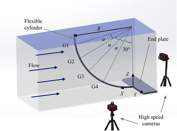
 $\rho$ is the fluid density. A schematic of the set-up is shown in figure 1.
A schematic of the experimental set-up, showing the locations of the high-speed cameras with respect to the curved cylinder and the incoming flow. The curved cylinder is shown in its convex orientation. Points G1–G4 are the spanwise locations at which flow visualizations were conducted, where  $\alpha$ in the figure is
 $15^{\circ }$.

The first natural frequency of the system in still water was measured to be  $f_1=1.15\ \textrm {Hz}$, using decay tests. The decay tests were performed by giving the cylinder an initial displacement with an amplitude of
 ${\approx }0.5D$ at its midpoint. The oscillations of the cylinder at its midpoint were recorded using a laser displacement sensor (Panasonic HL-G125) and were used to measure the natural frequency and damping ratio of the system. The natural frequency of the first mode of the system was used to calculate the reduced velocity of the system as
 $U^{*}=U/(\,{f_1 D})$, where
 $U$ is the flow velocity, and
 $f_1$ is the fundamental frequency of the system. The damping ratio associated with the excitation of the first mode of the structure was found using decay tests to be
 $\zeta = 0.0245$.
The flexible cylinder was marked with uniformly distributed black dots along its length in the spanwise direction,  $z$, at
 $0.038 \pm 0.001\ \textrm {m}$ intervals. A total of 14 points were marked along the length of the cylinder. The oscillations of these dots were captured in the CF direction using two side-by-side synchronized high-speed cameras (the Flare 2MP CMOS Cameras with high-speed DVR Core). This set-up enabled the recording of two synchronized videos at
 $2048 \times 1088$ resolution at frame rates up to 264 f.p.s. The cameras were equipped with a set of Navitar 17 mm Lens, f/1.4,
 $1''$ format lenses. A motion tracking software, Cabrillo Tracker, that is an optical pattern recognition software, was utilized to track the location of the cylinder markers which enabled synchronized spatially resolved measurements of the cylinder's oscillations in the CF direction. The motion tracking software uses cross-correlation of successive images of the motion recorded via high-speed cameras to track the location of the cylinder markings with an error margin of less than 2 % of the motion amplitude in the CF direction, calculated through black marked feature pixel dimensions. The first high-speed camera was placed underneath the water tunnel's test section to record the oscillations of the lower part of the cylinder and the second camera was placed at the downstream window of the water tunnel and recorded the oscillations of the upper part of the cylinder. The captured videos were inputs to the tracking software, which created synchronized displacement time histories in the CF direction at these discrete points. These data points were used to reconstruct a continuous response of the cylinder using a technique based on the modal analysis method, implementing a modal assurance criterion (MAC). Oscillations were observed in both the CF and IL directions at each point along the length of the cylinder, however, the amplitude of the IL oscillations was an order of magnitude smaller than the amplitude of the CF oscillations, and therefore in this work we only report the CF amplitude of oscillations.
Assuming sinusoidal mode shapes for the cylinder, its approximate response can be expressed in matrix form as a linear combination of its mode shapes (Chaplin et al. Reference Chaplin, Bearman, Huarte and Pattenden2005; Seyed-Aghazadeh & Modarres-Sadeghi Reference Seyed-Aghazadeh and Modarres-Sadeghi2016)
 \begin{equation} \boldsymbol{Y}(z, t)=\boldsymbol{\varPsi}(z) \boldsymbol{Y}_{M}(t), \end{equation}
where,  $\boldsymbol {Y}(z, t)=[\boldsymbol {y}(z_{1}, t), \boldsymbol {y}(z_{2}, t), \ldots ]$ is the matrix of measured displacements in which the rows consist of the CF displacements, measured at individual points along the cylinder,
 $\boldsymbol {\varPsi }(z)=[\boldsymbol {\varPsi }_{\boldsymbol {1}}, \boldsymbol {\varPsi }_{\boldsymbol {2}}, \boldsymbol {\varPsi }_{\boldsymbol {3}}, \ldots ]$ is the displacement modal shape matrix in which each column consists of normalized sinusoidal mode shapes at different points along the cylinder at each mode number,
 $M$, normalized to be 1 at their maxima,
 $\boldsymbol {Y}_{M}=[\boldsymbol {y}_{M_1}(t), \boldsymbol {y}_{M_2}(t), \boldsymbol {y}_{M_3}(t), \ldots ]$ is the modal contribution matrix, in which each row consists of row vectors of time series of each mode's contribution to the overall response. In this method, first the modal contribution matrix,
 $\boldsymbol {Y}_{M}(t)$, is calculated based on the measured time histories, and then the modal expansion theorem in conjunction with MAC is applied to obtain the response of the system at any arbitrary point along the cylinder. The use of MAC in the response reconstruction of a flexible cylinder was introduced recently (Seyed-Aghazadeh & Modarres-Sadeghi Reference Seyed-Aghazadeh and Modarres-Sadeghi2016).
In order to reconstruct the response of the system, 14 measurement points together with the two boundaries, which were fixed during the oscillations, were considered. For each case, the response was recorded using the two synchronized high-speed cameras at 240 f.p.s. at pixel resolution of  $2048 \times 1080$, capturing at least 20 cycles of oscillations. The selected recording frequency of 240 f.p.s., together with the number of measured discrete points along the length of the cylinder, guaranteed that higher frequencies, up to the seventh mode, can be captured following the Nyquist–Shannon criterion.
Flow visualization tests were conducted to study vortex shedding patterns in the wake of the cylinder in both the convex and the concave orientations. Hydrogen bubble generation was used for flow visualization. Hydrogen bubbles were generated through the electrolysis of water. A platinum wire with a diameter of 0.0508 mm was strung across the test section perpendicular to the flow and the length of the cylinder. The platinum wire served as an anode, while a 100 V, 2 A power supply positively charged a graphite plate to serve as a cathode. The potential between the two caused a build-up of hydrogen bubbles on the platinum wire. The bubbles separated from the wire once their diameter exceeded the wire diameter, creating a bubble film used to view the wake structure. Further detailed description of the system used for the hydrogen bubble generation has been documented previously (Seyed-Aghazadeh & Modarres-Sadeghi Reference Seyed-Aghazadeh and Modarres-Sadeghi2015). Two high-speed cameras placed underneath and at the top of the water tunnel test section were employed to record the instantaneous wake structure from the bottom and top views at four spanwise locations along the length of the cylinder. The spanwise flow visualizations were conducted at locations of  $z=[0.83, 0.67, 0.50, 0.33]$, also marked as G1–G4 in figure 1, where
 $z$ is the dimensionless spanwise location normalized by the length of the curved cylinder. The spanwise locations of the flow visualization points are 15 degrees apart from each other (
 $\alpha =15^{\circ }$), and the last point (G4) is located at the spanwise location
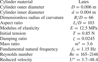
 $30^{\circ }$ away from the lower end of the cylinder. Details of the test matrix and governing non-dimensional system parameters are given in table 1.
Experimental parameters and the cylinder's structural characteristics.

3. The overall view of the response
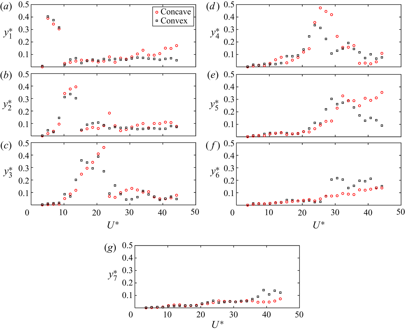
The cylinder's displacement in the CF direction was measured for both the convex and the concave orientations, where the flow velocity was increased from zero in small steps. At each flow velocity, the cylinder's oscillations were recorded using the two high-speed cameras, and a continuous response of the system along the length of the cylinder was reconstructed using the modal reconstruction technique, discussed in the previous section. Figure 2 shows the root-mean-square (r.m.s.) values of the modal weights, normalized by the diameter of the cylinder, at varying reduced velocities in the CF direction for the first seven modes. Using 14 measurement points along with the two fixed boundaries guaranteed that modes up to the seventh mode can be reconstructed following the Nyquist–Shannon criterion. For both the convex and the concave orientations, oscillations start at a reduced velocity of around  $U^{*}\approx 5.1$ at the first mode, reach a maximum value of
 $y^{*}\approx 0.4$ and then decrease at higher reduced velocities, where the second mode contribution starts to increase. The modal contributions at the first mode are very similar between the concave and the convex orientations for reduced velocities in the range of
 $U^{*}=3.7 - 33.5$. At higher reduced velocities, in the range of
 $U^{*}=35.3 - 48.3$, the relatively low contributions from the first mode exhibit larger values in the concave orientation compared with those in the convex orientation. The VIV response observed for both the concave and the convex orientations exhibits mainly multi-modal behaviour, where a combination of adjacent modes is excited over a range of reduced velocities. While the first mode is dominant at lower reduced velocities, the contributions of higher modes increase at higher reduced velocities. The maximum r.m.s. values for the first five modes stay at values of approximately
 $y^{*}\approx 0.4$. The maximum modal contributions decrease at higher modes (modes 6 and 7) to values of approximately
 $y^{*}\approx 0.2$ in the range of reduced velocities tested. While the r.m.s. values for modal contributions at the first mode are very similar between the concave and the convex orientations, the maximum values of modal contributions at higher modes (modes 2 to 5) are smaller for the convex orientation compared with those in the concave orientation. At higher modes of 6 and 7, while the modal weights stay similarly low for low reduced velocities, the contributions from these modes increase for the convex orientation compared with those observed in the concave orientation. In previous studies of VIV of a flexibly mounted rigid curved cylinder, maximum amplitudes of oscillations have been observed to be in the same range for the concave and the convex orientations (Seyed-Aghazadeh et al. Reference Seyed-Aghazadeh, Budz and Modarres-Sadeghi2015a).
The r.m.s. values of normalized modal weights vs the reduced velocity for the first seven modes of the concave and the convex orientations.

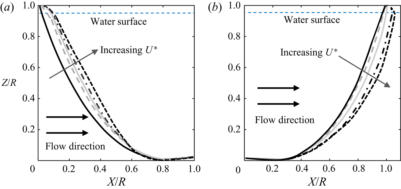
Mean profile of the cylinder, along its height,  $Z$, is plotted in figure 3 at five sample reduced velocities for both the convex and the concave orientations. In the convex orientation (figure 3a), the cylinder holds its curvature at low reduced velocities, and as the reduced velocity is increased, the cylinder is deflected by the mean inflow into an almost inclined configuration in the top 90 % of its height (
 $Z/R\approx 0.1 - 1$) at the highest reduced velocity of
 $U^{*}=39.1$. The cylinder in the concave orientation (figure 3b), however, holds its curved configuration for all reduced velocities tested.
Mean profile for (a) the convex and (b) the concave orientations at sample reduced velocities of  $U^{*}=7.4, 11.16, 22.3, 27.9$ and
 $39.1$.

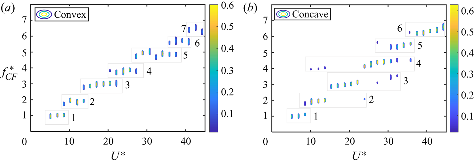
The dimensionless frequency of oscillations vs the reduced velocity is shown in figure 4 for both the convex and the concave orientations. The plots are formed by calculating the fast Fourier transforms of displacement time series along the length of the cylinder using the continuous reconstructed response of the cylinder at a given value of reduced velocity, normalizing them by the fundamental frequency of the system and plotting the frequencies whose magnitudes are at least 10 % of the dominant frequency. In the plots, the grey boxes and the numbers next to them give the structural mode numbers excited in that range of reduced velocities. These mode numbers are identified from the dominant modal contributions at each reduced velocity as plotted in figure 2. Later, in § 4.1, we will discuss how plots of spanwise frequencies of oscillations can help with identifying and understanding combined dominant frequencies of oscillations and their corresponding structural modes at each reduced velocity.
The dominant normalized frequency content vs the reduced velocity for (a) the convex and (b) the concave orientations.

In the convex orientation (figure 4a), frequencies up to the seventh harmonic frequency with its corresponding seventh structural mode are excited. In this orientation, oscillations start at a reduced velocity of  $U^{*}=5.1$, where the first harmonic frequency is dominant with its corresponding first structural mode. In the reduced velocity range of
 $U^{*}=5.1 - 8.5$, the first harmonic frequency with its corresponding first structural mode dominates the VIV response of the system. At the reduced velocity of
 $U^{*}=8.5$, where transition from mode 1 to mode 2 occurs, the mono-frequency VIV response of the system switches to multi-frequency oscillations, where the first harmonic frequency still dominates the response and small contributions from the second harmonic frequency, with its corresponding second structural mode, are also observed. After the multi-frequency excitation at
 $U^{*}=8.5$, mono-frequency excitation of mode 2 of the structure is observed over a range of reduced velocities (
 $U^{*}=10.2 - 11.9$), followed again by a multi-frequency response, this time at
 $U^{*}=13.6$, where contributions of mode 2 and mode 3 are observed, as the response transitions to a mono-frequency response of mode 3 at higher reduced velocities. This scenario continues for each mode transition: from mode 3 to 4, from 4 to 5, from 5 to 6 and from 6 to 7 at higher reduced velocities. Overall, the frequency content of the VIV response in the convex orientation exhibits mainly mono-frequency excitation, except at the reduced velocities at which transition from lower modes to higher modes occur. This type of VIV response indicates a mainly standing-wave behaviour, and has been previously observed for high mass ratio vertical flexible cylinders (Matsumoto et al. Reference Matsumoto, Shiraishi, Kitazawa, Knisely, Shirato, Kim and Tsujii1990; Chen et al. Reference Chen, Zhang, Li and Hu2015).
The frequency contents at varying reduced velocities in the concave orientation are shown in figure 4(b). Similar to the convex orientation, oscillations start at a reduced velocity of  $U^{*}=5.1$, where the first harmonic frequency is dominant with its corresponding first structural mode. Contrary to the convex orientation, in the concave orientation multi-frequency oscillations dominate the VIV response. Also, while in the convex orientation, the multi-frequency oscillations at the transition reduced velocities only involve the adjacent modes, in the concave orientation, modes other than the adjacent ones are also involved in the VIV response of the system. In the reduced velocity range of
 $U^{*}=10.2 - 13.6$, while the second harmonic frequency with its corresponding second structural mode dominates the response, contributions from the fourth harmonic frequency with its corresponding fourth structural mode are also observed. Similarly, in the reduced velocity range of
 $U^{*}=27.2 - 32.3$, while the VIV response is mainly dominated by the fourth harmonic and its corresponding fourth structural mode, contributions from the third and the fifth harmonics with their corresponding third and fifth structural mode shapes are also observed. The VIV responses consisting of a combination of several modes with comparable amplitudes, similar to those observed in the concave orientation, are known to be a signature of mainly travelling wave behaviour of the structure, and have been observed also for low mass ratio straight flexible cylinders (Chaplin et al. Reference Chaplin, Bearman, Huarte and Pattenden2005; Huera-Huarte, Bangash & González Reference Huera-Huarte, Bangash and González2016; Seyed-Aghazadeh & Modarres-Sadeghi Reference Seyed-Aghazadeh and Modarres-Sadeghi2016; Seyed-Aghazadeh et al. Reference Seyed-Aghazadeh, Edraki and Modarres-Sadeghi2019) and curved flexible cylinders in shear flow (Zhu et al. Reference Zhu, Lin and Gao2019a). As shown in figure 3, as the reduced velocity is increased in the concave orientation, the concavity of the cylinder is increased, which results in increased tension in the cylinder, and higher effective natural frequencies compared with the cylinder in the convex orientation subjected to the same incoming flow velocity. This difference suggests that at the same incoming flow velocity, a lower mode of the cylinder will be excited in the concave orientation compared with the convex orientation, which is in agreement with what is observed in figure 4.
Overall, the lock-in regions for each mode are relatively smaller for the curved cylinder in the convex orientation compared with those in the concave orientation, such that frequencies up to the seventh harmonic are excited in the convex orientation while frequencies up to the sixth harmonic are excited in the concave orientation. Similar extended lock-in ranges were previously observed in the VIV response of a 1 degree of freedom (DOF) flexibly mounted rigid curved cylinder in the concave orientation (Seyed-Aghazadeh et al. Reference Seyed-Aghazadeh, Budz and Modarres-Sadeghi2015a). This extended lock-in range was associated with the range of reduced velocities for which higher harmonics of the flow forces dominated the response and the curved cylinder in the concave orientation was excited by these higher harmonic forces. For the curved flexible cylinder in the present study, while the lock-in range is the same for the first mode oscillations in both the convex and the concave orientations, the extended lock-in regions in the concave orientation compared with those observed in the convex orientation are particularly observed at higher reduced velocity ranges at which higher modes are excited. The extended lock-in ranges in the concave orientation presumably can be associated not only with the higher harmonic flow force components as observed for flexibly mounted curved cylinders, but also to the mean flow profile of the flexible cylinder: in the concave orientation, the cylinder keeps its curvature and remains curved, even at the very high flow velocities tested, while in the convex orientation, the cylinder deforms into more of an inclined cylinder at high reduced velocities. For a curved cylinder in flow, the incident angle of the inflow varies along the span. As the cylinder loses its curvature at high reduced velocities in the convex orientation, the lower part of the cylinder that was originally oriented mainly in line with the flow makes a larger angle with the incoming flow (figure 3a) and contributes more to the excitation of the cylinder. In the concave orientation, however, as the reduced velocity is increased, the cylinder orients itself such that a larger part of its lower part becomes in line with the flow. This difference in the cylinder orientation at higher reduced velocities results in the excitation of higher modes in the convex orientation compared with the concave orientation.
4. Sample cases of the response
In this section, the response of the system at seven sample reduced velocities of  $U^{*}=6.8$, 8.5, 10.2
 $,$ 13.6, 20.4, 27.2 and
 $35.7$ is considered. The goal here is to discuss the differences in the VIV response of the system in terms of temporal and spatial amplitudes and frequency contents for the convex and the concave orientations at the same reduced velocities. These sample reduced velocities are selected such that they cover both mono-frequency and multi-frequency excitations and transitions from the lower mode to the higher mode excitations in the VIV response of the system. At
 $U^{*}=6.8$, the first mode is dominant in both the concave and the convex orientations. At
 $U^{*}=8.5$, both the first and the second modes contribute to the VIV response in both the concave and the convex orientations. The remaining samples at reduced velocities of
 $U^{*}=10.2$, 13.6, 20.4, 27.2 and
 $35.7$ are selected such that the modal contributions are different for the convex and the concave orientations.
4.1. The structural response at sample reduced velocities
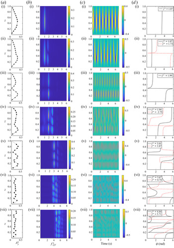
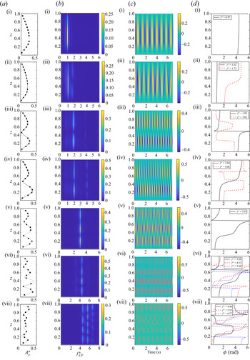
Figures 5 and 6 show the VIV response of the flexible cylinder in the convex and the concave orientations, respectively, at the sample reduced velocities of  $U^{*}=6.8$, 8.5, 10.2, 13.6, 20.4, 27.2 and
 $35.7$. The plots in the first column from the left in both figures show the dimensionless r.m.s. of amplitudes of oscillations along the cylinder's length. The magnitudes of the measured discrete experimental points are plotted on top of the reconstructed response to show how the reconstructed response matches the experimental measurements. The plots in the second column show the frequency contents of the structural response, normalized by the fundamental natural frequency, along the cylinder's length. The plots in the third column show the time histories of the amplitudes of oscillations along the length, and the plots in the fourth column show the spanwise evolution of the phase angles, for the selected frequencies which contribute to the VIV response of the system. This spanwise evolution of the phase angles is used to study the standing or travelling character of each excited temporal response, following the technique suggested by Lucor, Mukundan & Triantafyllou (Reference Lucor, Mukundan and Triantafyllou2006). To calculate these phases, we assume that we can approximate the structure's response using
 $N + 1$ temporal Fourier modes
 \begin{equation} y(z, t) \approx
\sum_{q={-}N / 2}^{N / 2} a_{q}^{y}(z) \exp [2 {\rm \pi}
\textrm{i} f_{q} t]=\sum_{q={-}N / 2}^{N /
2}\big|a_{q}^{y}\big|(z) \exp [\textrm{i}(2
{\rm \pi} f_{q} t+\phi_{q}^{y}(z))],
\end{equation}
where  $f_q$ is the frequency associated with the
 $q\textrm {th}$ mode. The complex modal coefficients of
 $a_{q}^{y}$ are written in terms of their moduli,
 $|a_{q}^{y}|$, and spatial phase angle,
 $\phi _{q}^{y}$. The phase angles plotted in figures 5 and 6 are wrapped to angles in the range of
 $[0,2{\rm \pi} ]$. An increasing spatial phase angle along the span (increasing
 $z$) denotes a travelling wave that travels from the upper end of the cylinder (
 $z=1$) toward the lower end of the cylinder (
 $z=0$). Modulations in the form of the sawtooth or zigzag in the evolution of the spatial phase angles are attributed to the underlying standing wave pattern (Bourguet et al. Reference Bourguet, Karniadakis and Triantafyllou2011a).
(a-i to a-vii) The dimensionless r.m.s. of amplitudes of oscillations (dashed line: reconstructed response, circles: experimental measurements), (b-i to b-vii) the frequency contents of the structural response, normalized by the fundamental natural frequency, (c-i to c-vii) the time histories of the amplitudes of oscillations and (d-i to d-vii) the spanwise evolution of selected temporal mode phase angles (wrapped) plotted vs the cylinder's length in the CF direction at reduced velocities of  $U^{*}=6.8$ (first row),
 $U^{*}=8.5$ (second row),
 $U^{*}=10.2$ (third row),
 $U^{*}=13.6$ (fourth row),
 $U^{*}=20.4$ (fifth row),
 $U^{*}=27.2$ (sixth row) and
 $U^{*}=35.7$ (seventh row) for the convex orientation.

(a-i to a-vii) The dimensionless r.m.s. of amplitudes of oscillations (dashed line: reconstructed response, circles: experimental measurements), (b-i to b-vii) the frequency contents of the structural response, normalized by the fundamental natural frequency, (c-i to c-vii) the time histories of the amplitudes of oscillations and (d-i to d-vii) the spanwise evolution of selected temporal mode phase angles (wrapped) plotted vs the cylinder's length in the CF direction at reduced velocities of  $U^{*}=6.8$ (first row),
 $U^{*}=8.5$ (second row),
 $U^{*}=10.2$ (third row),
 $U^{*}=13.6$ (fourth row),
 $U^{*}=20.4$ (fifth row),
 $U^{*}=27.2$ (sixth row) and
 $U^{*}=35.7$ (seventh row) for the concave orientation.

At the reduced velocity of  $U^{*}=6.8$, the VIV responses in the concave and the convex orientations are very similar. Asymmetric amplitudes of oscillations are observed for both orientations (panels (a-i)), where the cylinder undergoes larger amplitudes of oscillations at spanwise regions close to the bottom fixed boundary of the cylinder (
 $z=0$), with a peak amplitude at
 $z \approx 0.4$. As shown in the frequency contents (panels (b-i)), in both orientations, the cylinder oscillates at a single frequency close to the first harmonic frequency of the system, and its first structural mode is excited in the CF direction. The structural mode is identified as there is no vibrational node with zero amplitude along the length of the cylinder, except for the two fixed boundaries (
 $z=0, 1$). The oscillation time histories (panels (c-i)) represent standing-wave behaviour along the length of the cylinder. This standing-wave behaviour is also evident through the constant phase values observed over the spanwise length of the cylinder in panels (d-i).
At the reduced velocity of  $U^{*}=8.5$, multi-frequency oscillations are observed in the VIV responses of both orientations (panels (b-ii)), where contributions from the first and the second harmonic frequencies are observed, together with their corresponding first and second structural modes. The first mode contributions are larger compared with those of the second mode for both the concave and the convex orientations. The spanwise time histories in panels (c-ii) exhibit travelling wave behaviour, which is a signature of the VIV response when mode switching is observed (Chaplin et al. Reference Chaplin, Bearman, Huarte and Pattenden2005; Huera-Huarte et al. Reference Huera-Huarte, Bangash and González2016; Seyed-Aghazadeh & Modarres-Sadeghi Reference Seyed-Aghazadeh and Modarres-Sadeghi2016; Seyed-Aghazadeh et al. Reference Seyed-Aghazadeh, Edraki and Modarres-Sadeghi2019; Zhu et al. Reference Zhu, Lin and Gao2019a). The travelling wave characteristics are also exhibited through an increase in the spanwise phase evolution in panels (d-ii), especially at the second harmonic frequency at
 $f^{*}=1.73$, where there is an increase in the phase values along the length of the cylinder in both the concave and the convex orientations. The increase in the phase values indicates the direction of the travelling wave that travels from the upper boundary towards the lower end of the cylinder in both the concave and the convex orientations. The direction of the travelling wave that does not change from the convex to the concave orientation can be presumably explained by the fact that the incident flow velocity, perpendicular to the axis of the cylinder, is relatively larger at the upper boundaries where the cylinder is mainly oriented perpendicular to the flow than the lower portions, where the cylinder is oriented in line with the flow. A travelling wave along the length of the cylinder from regions with high flow velocities towards regions of low flow velocity has been previously observed in the VIV response of flexible cylinders when placed in sheared flow (Bourguet et al. Reference Bourguet, Karniadakis and Triantafyllou2011a).
As the reduced velocity is increased to  $U^{*}=10.2$, a mainly second mode response is observed in the amplitude responses for both the convex and the concave orientations (panels (a-iii)). This is clear by observing a node at
 $z \approx 0.45$. The amplitudes of these oscillations are asymmetric with respect to the midpoint of the cylinder, and the cylinder undergoes larger-amplitude oscillations in the region closer to its lower end. At this reduced velocity, the main mode that is excited, according to the frequency contents of panels (b-iii), is the second mode for both orientations. In the convex orientation, the second mode is the only mode that is excited, and the response is dominated by this mono-frequency excitation (figure 5b-iii). In the concave orientation, however, besides the second harmonic frequency and its corresponding second structural mode, relatively smaller, but existing contributions from the fourth harmonic frequency and its corresponding fourth structural mode is also observed (figure 6b-iii), making the response in the concave orientation a multi-modal response. The spanwise time histories exhibit travelling wave behaviour for both orientations (panels (c-iii)). This travelling wave behaviour is more clearly observed in the spanwise phase evolution of panels (d-iii). From these plots, the travelling wave character of the response at the second harmonic frequencies (
 $f^{*}=1.99$ in the convex orientation and
 $f^{*}=1.89$ in the concave orientation) is clear from the increase of the phase values along the length of the cylinder. In the concave orientation, the spanwise phase evolution at the fourth harmonic frequency (
 $f^{*}=3.82$) exhibits a combination of travelling waves in two opposite directions, where the phase angle decreases at the spanwise locations close to the vibration nodes (
 $z\approx 0.3$ and 0.6). This combination of two travelling waves results in a mainly standing-wave behaviour of the fourth harmonic component.
At the reduced velocity of  $U^{*}=13.6$, the difference in the VIV response between the convex and the concave orientations becomes very clear. In both orientations the amplitude responses exhibit a mainly second mode excitation, with asymmetric distribution of the amplitudes of oscillations (larger amplitudes closer to the lower end of the cylinder). In the convex orientation, the node at
 $z \approx 0.4$ that did exist for
 $U^{*}=10.2$, is changed to a point with a small, but non-zero, amplitude relative to the rest of the cylinder (figure 5a-iv). This is a sign of a mainly travelling wave response in the cylinder. In the concave orientation too, this deviation of the node from zero amplitude does exist (figure 6a-iv), but the deviation is much smaller, indicating some contributions of the travelling wave in the response, but not as much as that observed in the convex orientation. In the convex orientation, besides the second mode that was the only excited mode at
 $U^{*}=10.2$, a large contribution of the third harmonic is also observed (figure 5b-iv). This reduced velocity corresponds to the range for the convex cylinder where a multi-modal response is observed as the cylinder's response moves from a purely second mode to a purely third mode as shown in figure 4(a). In the concave orientation, the response is very similar to that at
 $U^{*}=10.2$: a large contribution from the second mode, and a small contribution from the fourth mode are observed in the response (figure 6b-iv). The travelling wave response in the convex orientation is clearly observed in the time histories (figure 5c-iv) and the spanwise phase evolution plot (figure 5d-iv). The phase evolutions at the second and third harmonic frequencies (
 $f^{*}=1.94$ and
 $f^{*}=2.75$) increase along the length of the cylinder (increasing
 $z$), indicating the direction of the travelling wave to be from the upper boundary towards the lower boundary of the cylinder. In the concave orientation (figure 6d-iv), while the phase angle evolution at the second harmonic frequency (
 $f^{*}=2.04$) exhibits a uniform direction of travelling wave, from the upper end towards the lower end, the phase evolution at the fourth harmonic frequency exhibits a combination of travelling waves at two opposite directions, similar to those observed at the reduced velocity of
 $U^{*}=10.2$, indicating a mainly standing-wave response.
At the reduced velocity of  $U^{*}=20.4$ too, the VIV responses in the convex and the concave orientations are very different. While in both orientations the amplitude response exhibits a mainly third mode excitation (panels (a-v)), with asymmetric distribution of the amplitudes of oscillations, the frequency content in the convex orientation exhibits a multi-frequency oscillation at modes three and four, and in the concave orientation the frequency content exhibits a mono-frequency oscillation at mode three. In the concave orientation, the spanwise time history of oscillations as well as the phase evolution at the third harmonic frequency, that increases along the length of the cylinder (increasing
 $z$), exhibit a uniform direction of travelling wave from the upper end toward the lower end. Non-zero amplitudes of oscillations at expected nodes for mode three oscillations at
 $z\approx 0.3$ and 0.6 (figure 6a-v) also confirm the existence of a travelling wave along the length of the cylinder. In the convex orientation (figure 5d-v), while the phase angle evolution at the third harmonic frequency (
 $f^{*}=3.01$) exhibits a uniform direction of travelling wave, from the upper end toward the lower end, the phase evolution at the fourth harmonic frequency (
 $f^{*}=3.87$) exhibits a combination of travelling waves at two opposite directions: the decrease in the phase angle at the two boundaries indicates that the direction of the travelling wave is from the lower boundary toward the upper boundary of the cylinder, and the increase at the midpoint of the cylinder indicates that the direction of the travelling wave is toward the lower end of the cylinder. These opposing travelling wave directions result in a more significant contribution of a standing wave in the response, as is also clear from the close-to-zero amplitudes at the nodes of figure 5(a-v).
As the reduced velocity is increased to  $U^{*}=27.2$, the VIV response of the cylinder exhibits multi-modal oscillations with dominant contributions from adjacent modes in both the convex and the concave orientations. In the convex orientation, the oscillations are dominated by equal contributions from the fourth and the fifth harmonics with their corresponding fourth and fifth structural modes (figure 5b-vi). These two dominant frequencies are excited in a broadband range of frequencies. Spanwise asymmetric amplitudes of oscillations (figure 5a-vi) with no node are observed at this reduced velocity, suggesting the existence of a travelling wave response in this orientation. The spanwise time histories exhibit the travelling wave behaviour for the convex orientation as well (figure 5c-vi). This travelling wave behaviour is more clearly observed in the spanwise phase evolution of figure 5(d-vi), in which the travelling wave character of the response at the fourth harmonic frequency (
 $f^{*}=3.67$) is clear from the increase of the phase values along the length of the cylinder, indicating that the direction of the travelling wave is from the upper boundary towards the lower boundary of the cylinder. The phase evolution at the fifth harmonic frequency (
 $f^{*}=4.74$) exhibits a combination of travelling waves in two opposite directions, where the phase angle increases at the lower boundary and decreases at the upper boundary. This behaviour suggests that there is a travelling wave at this mode, travelling from the spanwise location of
 $z\approx 0.4$ toward the boundaries. In the concave orientation, while the dominant frequency of oscillations contributing to the VIV response of the system is the fourth harmonic frequency with its corresponding fourth structural mode, small contributions from the third and the fifth harmonics are also observed with their corresponding third and fifth structural modes, respectively (figure 6b-vi). Similar to the convex orientation, spanwise asymmetric amplitudes of oscillations (figure 6a-vi) with no nodes are observed at this reduced velocity, suggesting a travelling wave response. The spanwise time histories too exhibit travelling wave behaviour for the concave orientation (figure 6c-vi), and the increase in the spanwise phase evolutions at the three contributing frequencies (figure 6d-vi) confirms a uniform direction of the travelling wave, from the upper end toward the lower end of the cylinder.
At the reduced velocity of  $U^{*}=35.7$, in the convex orientation, broadband excitation at frequencies close to the fifth and the sixth harmonics with their corresponding structural modes is observed. Very small contributions of the seventh mode are also visible in the frequency contents of the response. Asymmetric amplitudes of oscillations are observed in this case as well (figure 5a-vii), where the cylinder undergoes larger amplitudes of oscillations at spanwise regions close to the upper fixed boundary of the cylinder (
 $z=1$). This observation is the opposite of what had been observed at lower reduced velocities, such as
 $U^{*}=8.5$ and
 $U^{*}=10.2$, where the large-amplitude oscillations were close to the lower boundary of the cylinder. The shift in the location of the maximum amplitude can be attributed to the mean profile of the cylinder in the convex orientation (figure 3a), which was changed to a more inclined configuration as the reduced velocity was increased, with almost 90 % of the spanwise length of the cylinder being inclined at
 $U^{*}=35.7$. As a result of this change, the lower part of the cylinder that was mainly parallel to the flow at lower reduced velocities becomes more perpendicular to the flow and acts less toward damping the oscillations. Previous studies on the VIV response of flexibly mounted curved cylinders have shown that addition of an IL extension to the lower part of a curved cylinder acts as a damper, which reduces the amplitude of oscillation (De Vecchi et al. Reference De Vecchi, Sherwin and Graham2009). The spanwise time histories exhibit travelling wave behaviour (figure 5c-vii). This travelling wave behaviour is more clearly observed in the spanwise phase evolution of figure 5(d-vii). From this plot, the travelling wave character of the response at the sixth harmonic frequency (
 $f^{*}=5.71$) exhibits a uniform direction of travelling wave, from the upper end toward the lower end. The phase evolution at the fifth harmonic frequency (
 $f^{*}=4.84$) exhibits a combination of travelling waves in two opposite directions, where the phase angle increases at the lower boundary and decreases at the upper boundary. This behaviour suggests that there is a travelling wave at this mode, travelling from the spanwise location of
 $z\approx 0.7$ toward the boundaries. This travelling wave behaviour is very similar to that observed at
 $U^{*}=27.2$. In the concave orientation, the VIV response of the cylinder consists of frequency contributions from the dominant fifth harmonic with contributions from the fourth and sixth harmonics, with their corresponding structural modes (figure 6b-vii). Similar to the convex orientation, the spanwise time histories exhibit travelling wave behaviour (figure 6c-vii). The spanwise phase evolution plot of figure 6(d-vii) shows that while the phase angle evolutions at the dominant fifth harmonic frequency (
 $f^{*}=5.55$) and the sixth harmonic frequency (
 $f^{*}=6.57$) exhibit a uniform direction of travelling wave, from the upper end toward the lower end, the phase evolution at the fourth harmonic frequency (
 $f^{*}=4.48$) exhibits a combination of travelling waves at two opposite directions, where the phase angle increases at the lower boundary and decreases at the upper boundary. This behaviour suggests that there is a travelling wave at this mode, travelling from the spanwise location of
 $z\approx 0.4$ toward the boundaries.
4.2. The wake at sample reduced velocities
In this section, we focus on the wake of the cylinder in both the convex and the concave orientations for four sample reduced velocities for which different types of responses have been observed in the cylinder.
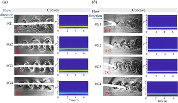
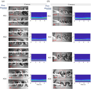
Figure 7 shows the wake of the cylinder at four spanwise locations highlighted in figure 1 at the reduced velocity of  $U^{*}=6.8$, for both the convex and the concave orientations. Together with the snapshots from the wake of the cylinder, scalograms are plotted at these spanwise locations, which show the temporal frequency content of the VIV response at these locations. In the convex orientation, two single vortices are shed in each cycle of oscillations (2S pattern) along the span of the cylinder. The vortex shedding frequency at this reduced velocity, obtained through the wake visualization recordings, is equal to the frequency of oscillations (
 $f_{vs}=f_{os} = 1.07\ \textrm {Hz}$ at
 $U^{*}=6.8$), which is a feature of a VIV response. Scalograms at the four spanwise locations exhibit a mono-frequency excitation at the first harmonic frequency of oscillations that dominates the VIV response of the flexible cylinder in the convex orientation. In the concave orientation, while the scalograms show a mono-frequency excitation along the length of the cylinder, the wake visualizations reveal two different shedding patterns along the span of the cylinder: for points of G1 and G2, closer to the upper end of the curved cylinder, which is mainly vertical (
 $z=0.83$, and 0.67), the vortex shedding pattern follows an
 $\textrm {S}+\textrm {P}$ shedding (a single vortex and a pair of vortices are shed in each period of oscillations). The observed
 $\textrm {S}+\textrm {P}$ shedding pattern covers the spanwise length of the cylinder close to the upper boundary, for which the amplitudes of oscillations are smaller, as observed in the amplitude plot of figure 6(a-i), compared with those observed at the lower part of the cylinder. At points G3 and G4, which are located at the lower part of the cylinder (
 $z=0.5$, and 0.33), the vortex shedding pattern switches to a 2S shedding.
Vortex shedding patterns in the wake of the curved cylinder at four points along the length (G1–G4) for the convex and the concave orientations at the reduced velocity of  $U^{*}=6.8$.

While the VIV response of the system consists of a mono-frequency excitation at the first harmonic with its corresponding first structural mode shape in both the convex and the concave orientations, the vortex shedding patterns vary along the span of the cylinder in the concave orientation. Variation of the vortex shedding patterns along the span of a curved cylinder has previously been observed in the VIV response of a curved cylinder placed in shear flow (Zhu et al. Reference Zhu, Lin and Gao2019a). This variation in shedding modes has been associated with the change in the vortex shedding timing and in the amplitude of oscillations. In their study of a curved flexible cylinder placed in sheared flow, Zhu et al. (Reference Zhu, Lin and Gao2019a) observed a change from a 2S shedding pattern to an  $\textrm {S}+\textrm {P}$ pattern at spanwise locations where the amplitude of oscillation was changed from relatively high to relatively low.
Figure 8 shows the wake of the cylinder and scalograms of the VIV response at the sample spanwise locations of G1–G4 at the reduced velocity of  $U^{*}=8.5$ in the convex and the concave orientations. At this reduced velocity, as discussed earlier in figures 5 and 6(b-ii), the VIV response of the system in both the convex and the concave orientations consists of multi-frequency oscillations, where the first and the second harmonic frequencies with their corresponding first and second structural mode shapes are excited along the length of the cylinder. As shown in figure 8, in the convex orientation, the spanwise wake of the cylinder shows intermittent vortex shedding patterns, where 2S and
 $\textrm {S}+\textrm {P}$ vortices are shed interchangeably over time at all the spanwise locations of G1–G4 (also seen inside the boxes drawn around the shed vortices). The spanwise intermittent shedding patterns observed in the wake of the cylinder confirm the results from the scalograms that exhibit the excitation at two dominant frequencies over time, where the second harmonic frequencies are widespread in time. In the concave orientation, the intermittent 2S and
 $\textrm {S}+\textrm {P}$ vortex shedding patterns are observed at locations of G1 and G4, close to the two ends of the cylinder. At these locations, similar to the convex orientation, the VIV response scalograms consist of multi-frequency excitations at the first two harmonics over time, where the second harmonic frequencies are widespread. The wake of the cylinder at spanwise locations of G2 and G3 is mainly of the
 $\textrm {S}+\textrm {P}$ vortex shedding pattern and the scalograms show that the VIV response of the system mainly consists of the dominant frequency at the first harmonic frequency over time, which confirms the periodic nature of the vortex shedding in the wake of the cylinder. Previous studies on the wake of a cylinder perturbed by a periodic fluctuation imposed on the inflow velocity (Konstantinidis, Balabani & Yianneskis Reference Konstantinidis, Balabani and Yianneskis2007) have shown that two interchangeable wake modes are possible (bimodal wake), in which the wake switches back and forth between two different vortex shedding modes. Such observation suggests that the spanwise intermittent shedding patterns observed in the wake of the cylinder in the present study are the result of the spanwise travelling waves discussed earlier (figures 5 and 6d-ii), which periodically perturb the flow around the cylinder.
Vortex shedding patterns in the wake of the curved cylinder at four points along the length (G1–G4) for the convex and the concave orientations at the reduced velocity of  $U^{*}=8.5$.

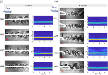
Figure 9 shows the wake of the cylinder and the VIV response scalograms at the sample spanwise locations of G1–G4 at the reduced velocity of  $U^{*}=10.2$ in the convex and the concave orientations. At this reduced velocity, in the convex orientation, the VIV response of the system exhibits mono-frequency excitation at the second harmonic frequency (as discussed in figure 5b-iii). The wake of the cylinder exhibits a uniform 2S vortex shedding along the span of the cylinder. The scalograms also show the dominant second harmonic frequency excitation over time. In the concave orientation, as seen in figure 6(b-iii), the VIV response of the system consists of the dominant second harmonic frequency with small contributions from the fourth harmonic frequency. The wake of the cylinder along the span of the cylinder shows intermittent 2S and
 $\textrm {S}+\textrm {P}$ vortex shedding patterns at the upper end of the cylinder (G1), and dominant 2S vortex shedding patterns at other spanwise locations along the length of the cylinder.
Vortex shedding patterns in the wake of the curved cylinder at four points along the length (G1–G4) for the convex (a) and the concave (b) orientations at the reduced velocity of  $U^{*}=10.2$.

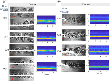
The wake of the cylinder and the VIV response scalograms at the sample spanwise locations of G1–G4 for the reduced velocity of  $U^{*}=13.6$ are shown in figure 10 for the convex and the concave orientations. In the convex orientation, the intermittent 2S and
 $\textrm {S}+\textrm {P}$ vortex shedding patterns persist at locations close to the two ends of the cylinder (G1 and G4), where the VIV response scalograms also exhibit multi-frequency excitation at frequencies close to the second and the third harmonic frequencies, with the frequency contents that change in time. At the spanwise location of G2, the VIV response scalogram exhibits dominant contributions from the second harmonic frequency with very small contributions from the third harmonic frequency. At the spanwise location of G3, the VIV response scalogram exhibits dominant contributions from the third harmonic frequency. The wake of the cylinder at points G2 and G3 consists of mainly 2P and
 $\textrm {S}+\textrm {P}$ vortex shedding patterns, respectively. At this reduced velocity in the concave orientation, the wake of the cylinder varies along the length of the cylinder: while a pair of vortices (2P vortex shedding) are shed at the upper end of the cylinder, 2S vortex shedding is observed at a lower location of G2, followed by
 $\textrm {S}+\textrm {P}$ shedding at G3 and a 2S shedding pattern at G4. At this reduced velocity, as also studied in figure 6(b-iv), the concave cylinder is mainly excited at the second and the fourth harmonic frequencies with asymmetric spanwise amplitudes of oscillations. The spanwise intermittent shedding patterns observed in the wake of the cylinder are in line with the travelling wave behaviour observed in the spanwise phase evolution results discussed earlier in figure 6(d-iv). The intermittent vortex shedding patterns in the convex orientation can be attributed to the travelling wave behaviour as discussed in figure 5(d-iv). In the concave orientation, minimal change in the spanwise phase evolutions discussed in figure 6(d-iv) at this reduced velocity indicated relatively smaller contributions of the travelling wave in the VIV response compared with those observed in the convex orientation. No intermittent wake mode is observed in the concave orientation for which minimal travelling wave contributions exist. Similar variation in the vortex shedding modes has been previously observed in VIV studies of a tapered cylinder (Techet, Hover & Triantafyllou Reference Techet, Hover and Triantafyllou1998; Seyed-Aghazadeh, Carlson & Modarres-Sadeghi Reference Seyed-Aghazadeh, Carlson and Modarres-Sadeghi2015b), for which the change in shedding patterns were attributed to the spanwise change in the effective reduced velocity as the diameter of the cylinder changes along its length. A hybrid mode was observed in which a 2S pattern was observed along the part of the span with the larger diameter and a 2P pattern along the part of the span with the smaller diameter.
Vortex shedding patterns in the wake of the curved cylinder at four points along the length (G1–G4) for the convex and the concave orientations at the reduced velocity of  $U^{*}=13.6$.

5. Conclusions
Laboratory measurements of VIV of a curved flexible cylinder, with a low mass ratio of  $m^{*}=3.6$ and tensioned under its own weight, were conducted for the cylinder placed in the concave and the convex orientations. The flexible cylinder was held fixed at its two ends, forming the shape of a quarter of a ring with a dimensionless radius of curvature of
 $R/D=66$. The VIV response of the cylinder was studied in the CF direction, where high-speed imaging technique was employed to record the oscillations of the cylinder for a reduced velocity range of
 $U^{*} = 3.7 - 48.4$, corresponding to a Reynolds number range of
 $Re = 165 - 2146$. Modal contributions for the first seven modes were observed for both orientations. While the first mode's contributions were almost similar in both orientations, in terms of the magnitudes of the modal contributions and the reduced velocity range over which the first mode oscillations were dominant, at higher reduced velocities, contributions from higher modes (modes 2 to 5) were larger for the concave orientation. The frequency contents of the VIV response exhibited different behaviours between the concave and the convex orientations: in the convex orientation, the VIV response exhibited mainly mono-frequency excitation over the range of reduced velocities tested, and multi-frequency oscillations were only observed at the transitional reduced velocities, where the VIV response was in transition from lower mode oscillations to higher ones. This behaviour was in line with previous observations of the VIV response of a flexible cylinder placed perpendicular to the incoming flow direction. However, in the concave orientation, the VIV response of the system exhibited mainly multi-frequency oscillations, where in addition to the dominant frequency of oscillations, contributions from other modes were observed in the response of the cylinder. Such multi-frequency oscillations were reported to be a feature of travelling wave behaviour in the VIV response of flexible cylinders. The travelling wave behaviour was also exhibited through spanwise phase angle evolution at these reduced velocities. Oscillations at frequencies as high as the seventh and the sixth harmonic frequencies were observed in the VIV response of the convex and the concave orientations, respectively. As the reduced velocity was increased, the cylinder in the convex orientation reconfigured itself into a mainly inclined cylinder, with a constant angle of inclination along the main part of its length as opposed to a varying angle of inclination in its original curved configuration. As a result of this change in configuration, the lower end of the convex cylinder became more perpendicular to the incoming flow, instead of being in line with it, and this change resulted in the excitation of higher modes in the convex orientation compared with the concave orientation. In the concave orientation, the cylinder kept its curved configuration up to the maximum reduced velocity tested here.
Hydrogen bubble flow visualizations were carried out for both the concave and the convex orientations at four spanwise locations along the curvature of the cylinder. In the convex orientation, spanwise interchangeable vortex shedding patterns were observed at reduced velocities at which multi-frequency oscillations were observed. At these reduced velocities, intermittent vortex shedding patterns were observed, where the vortex shedding patterns varied over time at the same spanwise location. At reduced velocities where mono-frequency excitation was observed, the spanwise vortex shedding patterns did not switch along the length of the cylinder and over time. In the concave orientation, even when single frequency oscillations were observed over the length of the cylinder, different vortex shedding patterns were observed at different locations along the length of the cylinder due to the asymmetric amplitudes of oscillations. Similar to the convex orientation, intermittent and interchangeable vortex shedding patterns were observed when multi-frequency oscillations were dominant in the VIV response of the system.
Overall, the vortex shedding patterns in the wake of a curved flexible cylinder exhibited two distinct features of temporal and spatial evolution that had not been observed previously in VIV of flexible cylinders: (a) the vortex shedding patterns exhibited temporal evolution, in that time-varying intermittent vortex shedding patterns at fixed locations along the span of the curved cylinder were observed in both the concave and the convex orientations. These alternating shedding patterns were linked to the existence of the spanwise travelling wave along the length of the cylinder, and (b) the vortex shedding patterns exhibited spatial evolution along the length of the cylinder, in that different vortex shedding patterns were observed along the length of the cylinder. The spatial change in the vortex shedding modes were attributed to the change in localized angle of inclination of the curved cylinder with respect to the incoming flow, which in turn contributed to the asymmetric amplitudes of oscillations along the length of the cylinder. While the details of the exact modes that are excited at each reduced velocity or the critical values of reduced velocities at which a transition from a lower mode to a higher mode is observed could change if the system parameters such as the externally applied tension, the original radius of curvature, etc. are changed, the overall behaviour of the curved cylinder in the concave and the convex orientations observed here are generally applicable to VIV of any curved flexible cylinder.
Acknowledgements
The authors report no conflict of interest.