
I. INTRODUCTION
It has been proved that boron nitride nanotubes (BNNTs) behave mechanically similar to carbon nanotubes (CNTs) providing exceptionally high tensile strength,Reference Zhi, Bando, Tang and Golberg1 excellent elastic modulus (>1 TPa),Reference Santosh, Maiti and Sood2–Reference Chopra and Zettl4 high failure strain,Reference Liao, Wang, Ju, Lien and Huang5,Reference Liao, Lian and Ju6 and high flexibility.Reference Liao, Wang, Ju, Lien and Huang5,Reference Golberg, Bando, Tang and Zhi7 Furthermore, BNNTs exhibit better thermal and oxidation stability so that they start oxidizing at higher temperature 950 °C as compared to CNTs at 500 °C,Reference Golberg, Bando, Tang and Zhi7–Reference Chen, Zou, Campbell and Caer9 which is an important advantage in their applications in combination with metal matrix composites (MMCs). The outstanding mechanical characteristics of BNNTs make them appropriate to combine with different engineering materials especially MMCs to strengthen their mechanical behavior and therefore to obtain lighter and stronger composite materials.
As reported in the literature, it has been proved that BNNTs are promising reinforcements and have successfully been used to reinforce polymeric,Reference Zhi, Bando, Tang, Honda, Kuwahara and Golberg10–Reference Zhi, Bando, Tang, Honda, Sato, Kuwahara and Golberg18 ceramic,Reference Bansal, Hurst and Choi19–Reference Lahiri, Singh, Benaduce, Seal, Kos and Agarwal22 glass,Reference Tatarko, Grasso, Porwal, Chlup, Saggar, Dlouhy and Reece23 and metallic composites.Reference Lahiri, Hadjikhani, Zhang, Xing, Li, Chen and Agarwal8,Reference Trivedi, Sharma and Harsha24–Reference Yamaguchi, Tang, Zhi, Bando, Shtansky and Golberg27 However, there are yet a limited number of published research regarding the influence of BNNT addition on the mechanical behaviors of reinforced MMCs. Al-based composites reinforced with BNNTs have been successfully synthesized using the method of spark plasma sintering by Lahiri et al.Reference Lahiri, Hadjikhani, Zhang, Xing, Li, Chen and Agarwal8 They achieved an improvement of more than 50% in yield strength and fracture strength of the composite with 5 vol% BNNT addition by micropillar compressive tests. Their microstructural analysis revealed the effective role of the reinforcement in load bearing and transfer through crack bridging and sword in sheath mechanisms.
Trivedi et al.Reference Trivedi, Sharma and Harsha24 evaluated the Young’s modulus of BNNT reinforced composites using a 3-D nanoscale representative volume element based on continuum mechanics and using finite element method for different matrix materials including ceramic, brass, structural alloy steel, malleable CI, Al-bronze, and monel. The modulus of composites increased by an amount of 15–55% depending on the matrix material. Xue et al.Reference Xue, Jiang, Bourgeois, Dai, Mitome, Zhang, Yamaguchi, Matveev, Tang, Bando, Tsuchiya and Golberg25 fabricated Al matrix composites reinforced with different fractions (up to 5 wt%) of multi-walled BNNTs using powder constituents by means of a high pressure torsion technique under 5 GPa pressurization. Their results show about 100% enhancement in the tensile strength of the Al matrix by adding 5 wt% BNNTs and about 50% improvement in Vickers hardness. Yamaguchi and coworkersReference Yamaguchi, Tang, Zhi, Bando, Shtansky and Golberg27 fabricated BNNT-Al matrix composite nanohybrids through magnetron sputtering of Al onto dispersed multi-walled BNNTs to create nanocrystalline shields of Al phase around individual nanotubes. The nanohybrids with a suitably thick aluminum coating (∼40 nm) withstood at least nine times higher stresses compared to a pure nonarmed Al metal. In another research, BNNT–Al composite ribbons were fabricated by Yamaguchi et al.Reference Yamaguchi, Pakdel, Zhi, Bando, Tang, Faerstein, Shtansky and Golberg26 with various multi-walled nanotube contents by melt spinning. They concluded that the reinforcements partially participate in carrying the applied tensile load and the ultimate tensile strength on the composite ribbons increased by 142% with 3 wt% nanotube addition in comparison to pure Al ribbons.
All the published experimental studies indicate the outstanding roles of BNNTs in strengthening various matrix materials including metals. They could improve strength, hardness, and stiffness of the BNNT-reinforced MMCs. However, it needs to be more studied for determining effects of nanotube-related parameters and also deformation mechanisms of these kinds of composites by assuming different loading and boundary conditions. In the present research, we therefore investigated influences of long (continuous) and short (discontinuous) BN nanotube inclusion on mechanical characteristics and elastic–plastic deformation mechanisms of Al-based matrix composites under tensile and compressive loadings based on molecular dynamics simulations. Stress–strain curves and mechanical properties of the composites were obtained. Moreover, effects of nanotube parameters including atomic fraction, diameter, length, and wall number were also examined.
II. MATERIALS
In the present work, embedded potential energy as a multibody potential function, introduced by Daw and Baskes,Reference Daw and Baskes28 was used to describe interactions between metallic atoms of the crystalline Al matrix. The parameter values provided by Mendelev et al.Reference Mendelev, Srolovitz, Ackland and Han29 were used to determine interatomic forces between the matrix particles. Tersoff potential function, developed by Tersoff,Reference Tersoff30 was adopted to define interatomic energy of boron and nitrogen atoms of the BN nanotube. The details of this kind of potential and its corresponding parameters are given in Ref. Reference Liao, Wang, Ju, Lien and Huang5. Lennard-Jones (LJ) potential function has widely been used in numerical simulations to describe van der Waals interaction at the interface of nanostructures (e.g., CNT and graphene) and MMCs.Reference Arcidiacono, Walther, Poulikakos, Passerone and Koumoutsakos31–Reference Rezaei, Deng, Tavakoli-Anbaran and Shariati39 We also used a 12-6 LJ potential function to represent the interface of the Al matrix and BNNT as defined in Eq. (1):
 $${E_{{\rm{LJ}}}} = 4\varepsilon \left[ {{{\left( {{\sigma \over r}} \right)}^{12}} - {{\left( {{\sigma \over r}} \right)}^6}} \right]\quad ,$$
where σ is the distance at which interatomic potential between two neighbor atoms is zero and ε is the depth of the potential well. These two parameters have been optimized for different identical elements and are available in the literature. However to determine them for unlike atoms, i.e., Al, B, and N in the present work, Lorentz–Berthelot mixing rules were utilized whereby the distance σ and the energy ε were estimated by the arithmetic average σ12 = (σ11 + σ22)/2 and the geometric average  ${\varepsilon _{12}} = \sqrt {{\varepsilon _{11}}{\varepsilon _{22}}}$, respectively, for the two interacting neighbor atoms 1 and 2. The parameter values σAl–Al = 2.57366 Å and εAl–Al = 0.50722 eV were taken from Ref. Reference Filippova, Kunavin and Pugachev40 for Al. The values σB–B = 3.453 Å and εB–B = 0.004116 eV for boron and σN–N = 3.365 Å and εN–N = 0.006281 eV for nitrogen were taken from Ref. Reference Kang and Hwang41. By using these values and according to Lorentz–Berthelot mixing rules, the following parameters were obtained for the three nonbonded interacting pairs in the composite samples: σAl–B = 3.01333 Å and εAl–B = 0.045692 eV; σAl–N = 2.96933 Å and εAl–N = 0.056443 eV; and σB−N = 3.409 Å and εB–N = 0.005058 eV.
For the nanocomposites reinforced with multi-walled nanotubes, the interactions between layers of the nanotubes were assumed of nonbonded type and were considered van der Waals forces according to the LJ potential as described in Eq. (1). This is the technique that has been used to represent interlayer interface of multi-walled nanotubes in the literature.Reference Mohammadpour and Awang42 Its corresponding parameters were σB–N and εB–N for nonequal atoms and σB–B, εB–B, σN–N, and εN–N for identical interacting atoms as described above. The cutoff distance of the LJ functions were set to rc = 9 Å that is equal to 2.78σave, where σave is the arithmetic average of all the associated σ values.
Overall, the total potential energy of the nanocomposite was thus obtained as summation of all the above-described potentials as following:
 $${E_{{\rm{total}}}} = {E_{{\rm{eam}}}} + {E_{{\rm{Tersoff}}}} + E_{{\rm{LJ}}}^{{\rm{Al}} - {\rm{B}}} + E_{{\rm{LJ}}}^{{\rm{Al}} - {\rm{N}}} + \left\{ {E_{{\rm{LJ}}}^{{\rm{B}} - {\rm{B}}} + E_{{\rm{LJ}}}^{{\rm{N}} - {\rm{N}}} + E_{{\rm{LJ}}}^{{\rm{B}} - {\rm{N}}}} \right\}\quad ,$$
where E eam, E Tersoff, and  $E_{{\rm{LJ}}}^{{\rm{i}} - {\rm{j}}}$, respectively, stand for embedded potential of the matrix, Tersoff potential of the nanotube, and LJ 12-6 potential of the nonbonded interactions between i and j atoms. The last three terms into the braces are only for the composites reinforced with multi-walled nanotubes.
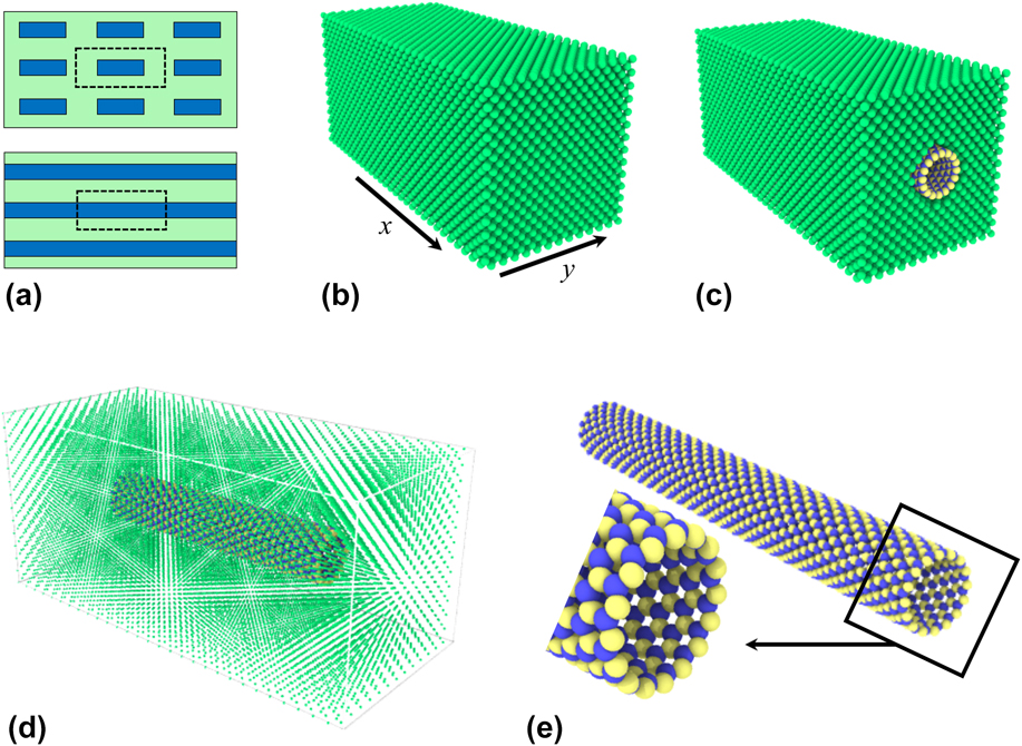
The schematic diagrams of BNNT–Al composites containing symmetrically embodied short (discontinuous) and long (continuous) BNNTs are illustrated in Fig. 1(a). The dashed boxes separate volume representative elements created for conducting tensile and compressive mechanical tests by MD simulations. The test samples of the pure Al matrix (with the normal crystalline directions [100], [010], and [001]) and nanocomposites reinforced with long (continuous) and short (discontinuous) BNNTs are shown in Figs. 1(b)–1(d), respectively. For the continuous case, the axial boundaries were assumed periodic to represent a real-life long continuous nanotube. The zigzag atomic structure of a single-walled BNNT (SWBNNT) is illustrated in Fig. 1(e), which is composed of an alternating arrangement of boron and nitrogen atoms in a hexagonal network. Dimensions of the samples were different depending on atomic fraction, diameter, and wall number of the reinforcement. For instance, for the composite reinforced with a 8.6 at.% single-walled nanotube of 12.8 Å in diameter, the dimensions were 117.5, 52.7, and 52.7 Å at x-, y-, and z-directions, respectively. In addition, the nanotube inclusion made all the composites lighter than the pure samples, for example, by 5.9% in this case. All the samples were loaded in x-direction parallel to the nanotube axis.
Schematic diagram of (a) nanocomposites reinforced with short and long BNNT, (b) pure Al matrix, (c) nanocomposite of long BNNT and matrix, (d) nanocomposite of short BNNT and matrix, and (e) atomic structure of a zigzag BN nanotube.

The samples were assumed periodic, denoted by “P”, in the axial direction x. The boundary conditions were set to free (denoted by “S”) or periodic in the transverse directions depending on the test case under consideration. Overall, the two boundary conditions P P S and P S S were applied on the pure and composite materials to examine their influence on the sample behavior. The time step Δt = 0.001 ps was used to integrate the equations of motion and the strain rate  ${\dot{\varepsilon }_x} = 0.00011{\rm{/ps}}$ was applied for loading the samples. The classic MD simulation package LAMMPS (Large-scale Atomic/Molecular Massively Parallel Simulator)Reference Plimpton43 was used to conduct the mechanical tests on the samples. An isothermal–isobaric ensemble, NPT, and a canonical ensemble, NVT, were used for both equilibrating and loading experiments, respectively. The system pressure was set to zero for NPT while the temperature was specified at T = 300 K for both ensembles. OVITOReference Stukowski44 was also utilized to visualize the atomistic configurations of the loaded and deformed samples.
III. RESULTS AND DISCUSSION
Before applying any test loading, the samples were first equilibrated for a 65 ps-duration process to make zero any possible boundary pressure and stress tensor resulted from the initial arrangement of the atoms. We first investigated the influence of long and short SWBNNT addition on tensile and compressive responses of the Al matrix, obtained their stress–strain curves, and then extracted their deformation mechanisms. We then used double-(DWBNNTs) and triple-walled BNNTs (TWBNNTs) to combine with the Al matrix and investigated their impacts on mechanical behaviors of the composite samples by imposing uniaxial tensile and compressive loadings.
A. Tensile loading
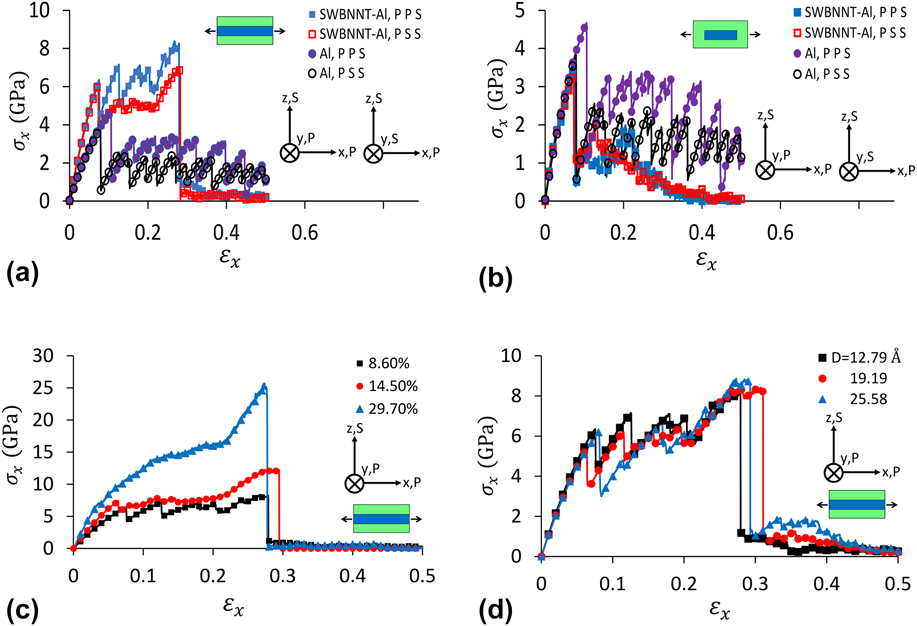
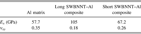
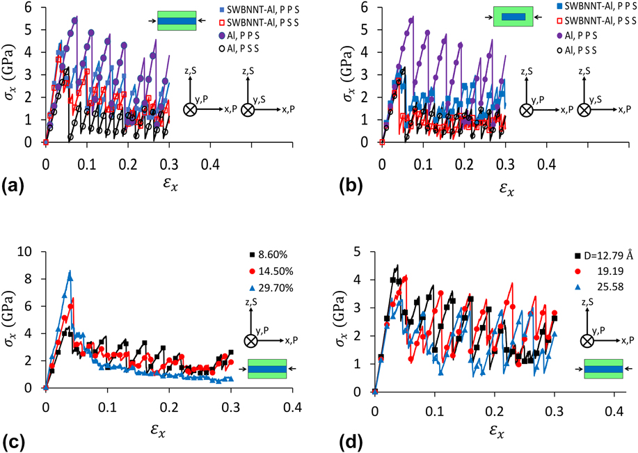
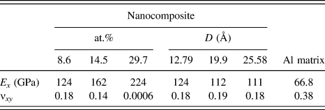
Both long and short SWBNNTs, respectively, with atomic fractions of 8.6 and 5.4 at.% were utilized to combine with the crystalline Al matrix and were subjected to uniaxial tensile loading for two different boundary conditions, i.e., P P S and P S S. Stress–strain curves of the long and short SWBNNT–Al nanocomposites are shown, respectively, in Figs. 2(a) and (b) in comparison to the pure Al matrix. The insets of these figures indicate the sample composition, coordinate system, and its corresponding boundary conditions. As can be seen in Fig. 2(a), the long nanotube addition (with atomic fraction of 8.6 at.% which is equivalent to 4.15 wt% in weight) significantly increased the yield and ultimate strengths of the matrix, respectively, from 4.67 to 6.35 and 8.38 GPa, respectively. They enhanced, respectively, by 36 and 79% owing to the outstanding strengthening role of the nanotube in both elastic and plastic regimes of the material. It is comparable with the experimental results of improvement in ultimate tensile strength of the Al matrix composite reinforced with 5 wt% BNNTs by 70% and 90%, respectively, without and with heat treatment of the matrix reported by Xue et al.Reference Xue, Jiang, Bourgeois, Dai, Mitome, Zhang, Yamaguchi, Matveev, Tang, Bando, Tsuchiya and Golberg25 The composite elastic modulus enhanced by 82% and 16%, respectively, for long and short nanotubes as shown in Table I. This increment in Young’s modulus is also comparable with the experimental enhancement of 133% in modulus of multi-walled BNNT-Al ribbon fabricated by Yamaguchi et al.Reference Yamaguchi, Pakdel, Zhi, Bando, Tang, Faerstein, Shtansky and Golberg26
Stress–strain curves of (a) long and (b) short SWBNNT–Al nanocomposites under uniaxial tensile loading in comparison to the pure Al matrix for different boundary conditions; and impacts of (c) atomic fraction and (d) diameter of nanotube on SWBNNT–Al nanocomposites for P P S boundary conditions. P and S stand for periodic and free boundary conditions, respectively.

Young’s modulus and Poisson’s ratio of the pure Al matrix and long/short SWBNNT–Al composites for the boundary conditions P P S under tension.

As can be seen in Fig. 2(a), by increasing the externally applied load, the composite sample first stretched elastically until the matrix underwent the yield stress at the applied strain of 0.076. It then plastically deformed until the nanotube and therefore the nanocomposite fractured at the applied strain of 0.267. On the other hand, as can be seen, the boundary condition did not considerably influenced the sample behavior especially the overall trend of the stress–strain curves except the ultimate strength which was slightly higher for the case P P S. As shown in Fig. 2(b) and Table I, the short nanotube addition increased the elastic modulus of the matrix. This enhancement demonstrates the effective contribution of the matrix–nanotube interface in load bearing and transfer in the elastic regime of the material response. However, the ultimate strength of the nanocomposite decreased. It can be attributed to these facts that the short nanotube did not directly contribute to withstand the applied load and the nanotube inclusion caused a cylindrical hollow space inside the matrix which reduced the integrity and therefore the resistance of the matrix structure against the applied load.
To investigate possible influence of the nanotube atomic fraction, two other long SWBNNT–Al samples with the atomic fractions of 14.5 and 29.7 at.% were created, equilibrated, and then subjected to a same tensile loading. As shown in Fig. 2(c), the strength and stiffness of the nanocomposites significantly increased by increasing the atomic fraction of the reinforcement. In fact, by increasing the atomic fraction, the nanotube could provide more resistance against the applied loading owing to its ultra-strong covalent bonded structure.
To determine possible impact of the nanotube diameter on mechanical response of the nanocomposite, two other long SWBNNT–Al samples with the nanotube diameters of 19.19 and 25.58 Å were constructed by keeping the nanotube atomic fraction constant, equilibrated, and then subjected to a same tensile loading. As shown in Fig. 2(d), the reinforcement diameter did not make significant influence in the total trend of the stress–strain curves and the composite behavior.
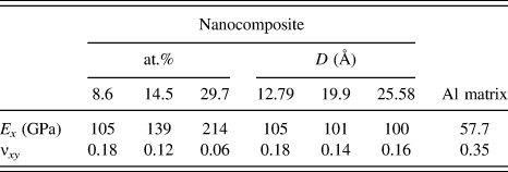
Table II shows the obtained Young’s modulus and Poisson’s ratio for long SWBNNT–Al nanocomposites for various atomic fractions of the reinforcement for P P S boundary conditions for which the nanotube diameter was set to 12.79 Å. The properties of the pure Al matrix are also included for the purpose of comparison. As can be seen, the nanocomposite elastic modulus significantly enhanced by increasing the nanotube fraction from 8.6 to 29.7 at.%. The Poisson’s ratio, however, remarkably decreased by increasing the nanotube fraction. These observations clearly indicate the outstanding reinforcing role of the nanotube inclusion in the elastic properties of the composite materials. Table II also shows the nanotube addition influence on the elastic characteristics of the SWBNNT–Al nanocomposite samples for different diameters of the reinforcement, i.e., D = 12.79, 19.9, and 25.58 Å with the same atomic fraction of 8.6 at.% in comparison to the pure Al sample for P P S boundary conditions. As can be seen, the impact of the diameter on the elastic properties was not significant. In other words, no noticeable change was observed in the composite properties by increasing the nanotube diameter.
Young’s modulus and Poisson’s ratio of long SWBNNT–Al nanocomposites under tension for different nanotube atomic fractions (at.%) and diameter (D) in comparison to pure Al for P P S boundary conditions.

B. Compressive loading
Figure 3(a) shows the obtained stress–strain curves of the nanocomposites reinforced with long SWBNNT of diameter D = 12.79 Å and atomic fraction 8.6 at.% for two different boundary conditions (P P S and P S S) in comparison to pure Al samples under compressive loading. For the P P S case, the long nanotube addition decreased the ultimate strength (by 19.6%) and yield strain (by 50%) of the nanocomposite. However, it improved the stiffness so that the elastic modulus modified by 86% from 66.8 to 124 GPa and the Poisson’s ratio decreased by 53% from 0.38 to 0.18 in comparison to the pure Al samples as shown in Table III. For the P S S case, the nanocomposite ultimate strength increased by 33% but the yield strain decreased by 36% by adding long nanotubes. However, as can be seen in Fig. 3(a), the stiffness of the composite sample significantly improved. A noticeable difference at the behavior of pure Al was observed by changing the boundary conditions as can be seen in Figs. 3(a) and 3(b). The nanotube inclusion restricted this difference and provided a similar behavior for the nanocomposites which made it almost independent of the boundary conditions.
Stress–strain curves of (a) long and (b) short SWBNNT–Al nanocomposites under uniaxial compressive loading in comparison to the pure Al matrix for different boundary conditions; and impacts of (c) atomic fraction and (d) diameter of reinforcement on SWBNNT–Al nanocomposites for P P S boundary conditions.

Young’s modulus and Poisson’s ratio of long SWBNNT–Al nanocomposites under compression for different nanotube atomic fractions (at.%) and diameter (D) in comparison to pure Al for P P S boundary conditions.

We also examined the influence of the reinforcement diameter and atomic fraction on the mechanical response of the nanocomposites reinforced with long BNNT for P P S boundary conditions under compression. Figure 3(c) shows the atomic stress curves versus the applied strain for three constructed samples of Al matrix nanocomposites reinforced with long SWBNNT of different atomic fractions, i.e., 8.6, 14.5, and 29.7 at.%. As can be seen, the atomic fraction caused an outstanding influence on the mechanical characteristics of nanocomposites so that the stiffness and strength dramatically increased by increasing the nanotube atomic fraction from 8.6 to 29.7 at.%. In addition, the elastic modulus increased by 85.6, 142.5, and 235.3% in comparison to the pure Al sample as shown in Table III, but the Poisson’s ratio decreased by increasing the atomic fraction. These observations indicate the prominent contribution of the nanotube in resisting the applied compressive loading in elastic regime. Figure 3(d) shows the stress–strain curves of three samples of SWBNNT–Al nanocomposites for the nanotube diameters D = 12.79, 19.19, and 25.58 Å exposed to uniaxial compressive loading. As can be seen, the nanotube diameter did not make significant influence on the mechanical responses of the composite samples to the applied compression load. Moreover, the Young’s modulus and Poisson’s ratio remained almost unchanged by increasing the reinforcement diameter as shown in Table III.
C. Deformation mechanisms
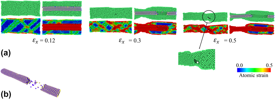
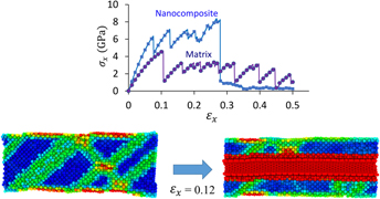
Figure 4(a) shows the deformation mechanism of the long SWBNNT–Al nanocomposite in a half sectional side view in comparison to the pure Al sample at different time steps of the applied strain under uniaxial tensile loading for the nanotube diameter D = 12.79 Å and atomic fraction of 8.6 at.% and the boundary conditions P P S. The top snapshots indicate the deformation mechanism of the pure and composite samples and the bottom ones indicate their corresponding colored atomic strains. As can be seen at the applied strain εx = 0.12, the pure Al matrix started plastic deformation through dislocation and propagation of the atoms along the maximum shearing planes. By increasing the applied strain, the pure sample plastically deformed and finally failed by breaking the atomic bonds along the slipping planes resulting in crack formation and therefore the fracture of the material as shown in the inset of Fig. 4(a). As shown in the right snapshots of Fig. 4(a), the nanotube presence significantly influenced the deformation process. The reinforcement blocked the growing path of the formed dislocations inside the matrix and therefore postponed the failure of the composite. The red regions of the nanotube and its interface with the matrix indicate their noteworthy contribution in bearing the externally applied load. The nanocomposite failure occurred by breaking the nanotube structure and then its slipping inside the matrix. Figure 4(b) shows the broken bonds and the fractured structure of the reinforcement under the applied tensile loading at the strain εx = 0.5 by disappearing the matrix atoms. The entire time evolution of the tensile deformation mechanism of the pure and composite samples is demonstrated in Supplementary Material Movies S1 and S2, respectively. Same deformation processes but in terms of colored atomic strain are also illustrated in Movies S3 and S4.
(a) Deformation mechanisms of the pure Al matrix and SWBNNT–Al nanocomposites under uniaxial tensile loading at various time steps of strain εx = 0.12, 0.3, and 0.5; and (b) failed atomic structure of the nanotube at εx = 0.5. Inset of (a) shows an enlarged view of the track formed inside the matrix. Bottom images of (a) illustrate the deformed structures of the samples in terms of atomic strain.

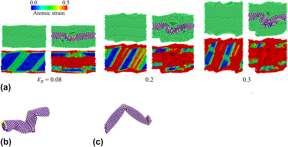
Figure 5(a) shows the deformed structures of the nanocomposite sample reinforced with long SWBNNT at different time steps of the applied compression load in comparison with the pure Al sample. As can be seen, the pure sample plastically deformed through dislocation nucleation and propagation along maximum shearing planes. The composite sample experienced a same deformation mechanism in which the nanotube could not provide a resistance to the shearing stress flow formed inside the matrix. The nanotube deformed along the propagation path of the dislocations and buckled under the compression load as shown in Fig. 5(b) by disappearing the Al atoms. The reinforcement under the compression load could not stand against the shear stress formed inside the matrix and did not provide any constraint against the growing path of the atomic dislocations across the material. Figure 5(c) shows the buckled structure of a SWBNNT which was separately modeled alone and put under a same compression load as the pure Al and nanocomposite samples. Comparing it with the buckled embedded nanotube shown in Fig. 5(b) exposed the noticeable influence of the matrix–reinforcement interface on the deformation mechanism of the nanotube during the loading process. The entire time evolution of the compressive deformation mechanism of the pure and composite samples is demonstrated in Supplementary Material Movies S5 and S6, respectively. Same deformation processes but in terms of colored atomic strain are also illustrated in Movies S7 and S8.
(a) Deformation mechanisms of the pure Al matrix and SWBNNT–Al nanocomposites under uniaxial compressive loading at various time steps of strain εx = 0.08, 0.2, and 0.3; (b) failed structure of the nanotube embedded in the matrix at εx = 0.3; and (c) failed structure of a separated SWBNNT individually loaded by same compression. Bottom images of (a) illustrate the deformed structures of the samples in terms of atomic strain.

D. Multi-walled BNNT-reinforced Al nanocomposites
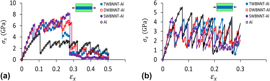
To determine possible impacts of the wall number of the nanotube, we created two other test samples of the nanocomposites reinforced with long DWBNNTs and TWBNNTs by keeping the atomic fraction of the nanotube constant at 8.6 at.% and with the boundary conditions P P S. The obtained results of atomic stresses versus the applied strain are shown in Fig. 6(a) for tension test and in Fig. 6(b) for compression in comparison to the pure Al matrix and SWBNNT–Al nanocomposite. As can be seen, the total trends of stresses of the nanocomposites were analogous and the wall number did not cause significant influence on the mechanical response of the composite samples except that a small difference in the yield and ultimate strengths was observed. These simulation observations demonstrate that the wall number is not a noteworthy factor to be considered in designing of metal matrix nanocomposites reinforced by BN nanotubes.
Stress–strain curves of long DWBNNT- and TWBNNT–Al nanocomposites under (a) tension and (b) compression in comparison to the pure Al matrix and SWBNNT–Al nanocomposite.

IV. CONCLUSION REMARKS
In summary, we used MD simulations to investigate the influence of SWBNNTs and multi-walled BNNTs addition and also impact of their related parameters, including length, atomic fraction, wall number, and boundary conditions on metal matrix nanocomposite behavior for both tension and compression loadings. Based on the extracted simulation results from the conducted mechanical tests on the constructed nanocomposite samples, the following prominent points could be concluded:
(1) Long BNNTs outstandingly enhanced tensile mechanical properties including elastic modulus and ultimate strength of nanocomposites by 82 and 72.9% for single-walled nanotube of atomic fraction 8.6 at.% and diameter 12.79 Å because of its direct contribution in bearing and transfer of the applied loading.
(2) Long nanotube addition effectively influenced deformation mechanism of composite samples under tensile loading and could provide effective barriers to growing paths of shearing slipping planes formed inside the Al matrix. The simulation results also revealed an interesting role of the reinforcement in bridging of cracks observed in loaded pure Al samples.
(3) In compression test, simulation results showed an effective reinforcing role of the nanotube in the elastic region of nanocomposite deformation so that the elastic modulus improved by 85.6% by adding long nanotubes with atomic fraction 8.6 at.% and diameter 12.79 Å. The nanotube deformed and buckled along shearing stress flows moved inside the composite under the applied compression.
(4) Diameter and wall number of the reinforcement remained no considerable effects on the nanocomposite mechanical behavior. But a strong dependence of the mechanical properties to the nanotube atomic fraction was observed.
The present research provides new insights into effective roles of BNNTs in strengthening MMCs and also effects of nanotube parameters which may be taken into account in designing and synthesizing of these new emerging composite materials for their potential applications especially in automotive and aerospace industries.
Supplementary Material
To view supplementary material for this article, please visit https://doi.org/10.1557/jmr.2018.93.