Introduction
Solid-state welding (SSW) is an important alternative to traditional, fusion-based welding, and can be useful for joining materials that have disparate melting points or contain brittle intermetallic compounds.Reference Cai, Daehn, Vivek, Li, Khan, Mishra and Komarasamy1,Reference Hovanski, Upadyay, Kleinbaum, Carlson, Boettcher and Ruokolainen2 Impact welding is one class of SSW technique that has been practiced as explosive weldingReference Findik3 and magnetic pulse weldingReference Psyk, Risch, Kinsey, Tekkaya and Kleiner4 for several decades.
In impact welding, as the name suggests, two or more pieces of metal are impacted with each other at a high speed, typically above 300 m/s, and at an oblique angle, typically 10° to 30°. The speed of impact causes jetting of the surface layers, which allows intimate contact of the nascent metallic surfaces; the high-pressure contact largely removes voids and results in a metallurgical bond between the materials. In addition to the ability to weld dissimilar materials, impact welding does not produce a heat-affected zone, a typically negative feature induced in traditional welding that changes the local temper condition of the material, often resulting in a softer region around the joint. When joints are created by impact the base-metal properties are retained in the joint. The interface that is formed can be, but is not necessarily always, as strong as the base metals.
Explosive welding cannot be practiced in traditional industrial settings due to handling, storage, and noise constraints. Magnetic pulse welding, an alternative to explosive welding, is a technique employing electromagnetic coils driven with large transient current pulses (more than 50,000 amps) to provide driving pressure to a metal sheet, in which an opposite current is induced due to the changing magnetic flux of the coil. In this process, an impact weld is created when a sheet of metal is repelled from the coil at a high speed, and then collides with a stationary target sheet at an appropriate impact angle. Magnetic pulse welding has limitations in terms of which materials and thicknesses can be used for welding sheet metals. Magnetic pulse welding is suitable for high conductivity materials, and the currents required to accelerate metals greater than 2 mm of thickness can damage the solenoid actuator coil itself through high magnetically induced pressures within the coil as well as through heating.Reference Berlin5
The vaporizing foil actuator welding (VFAW) technique shows promise as a small-scale, low-energy impact welding technology for joining both similar and dissimilar metals. In this article, we discuss the various aspects of the VFAW method, which has been used for welding a wide variety of material combinations including aluminum-steel, aluminum-magnesium, aluminum-titanium, aluminum-copper, titanium-steel, copper-titanium, and copper-bulk metallic glass.Reference Vivek, Hansen, Liu and Daehn6,Reference Vivek, Presley, Flores, Hutchinson and Daehn7 The aluminum-steel pairing, given its relevance to the vehicle weight reduction effort, has especially been a major focus of development for VFAW. The results of welding the 5000 and 6000 series aluminum alloys (magnesium and silicon-magnesium-based, respectively) with advanced and ultrahigh-strength steels are described here. A relatively portable VFAW system that can be used for research as well as low volume production is also described.
VFAW process
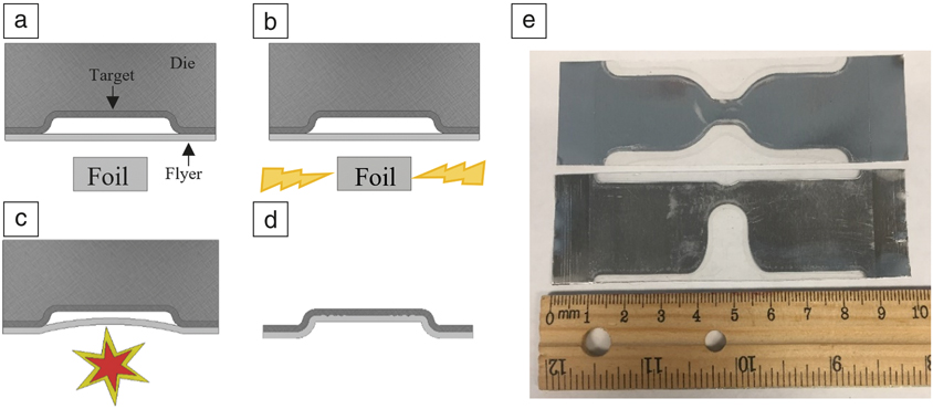
The VFAW process uses a large electrical current from the discharge of a capacitor bank to rapidly sublimate or vaporize a small portion of a confined conductive foil. The rapidly expanding gases produced from the sublimation of the foil can be used for various forms of high-velocity joining and forming applications. A step-by-step illustration of the process is shown in Figure 1a–d.Reference Kapil, Lee, Vivek, Cooper, Hetrick and Daehn8 Several geometric configurations can be used to create an impact weld. Figure 1 shows the acceleration of a flyer sheet into a dimple in a target sheet. Under the action of a high current, the foil itself vaporizes, producing high pressure, which pushes the flyer toward the target at a high speed. The fast and oblique impact produces the weld. An insulated tool steel anvil behind the foil provides for a high-efficiency launch, while a support die behind the target prevents unwanted deformation.
The vaporizing foil actuator welding (VFAW) process. (a) Stack with dimpled target, flyer sheet, and foil; (b) energization of the foil with capacitor bank discharge; (c) foil vaporization leading to launch of flyer; and (d) welded target and flyer sheets. (e) Foil actuator designs used in this work.Reference Kapil, Lee, Vivek, Cooper, Hetrick and Daehn8

The conductive foil is typically cut from aluminum shim stock. Shim stocks are commonly used in high precision work, such as in precision metalworking, and are available in several precise thicknesses, making them ideal starting materials for the production of foil actuators. The thickness of foils demonstrated to be useful in this process range from 0.0254 mm to 0.127 mm (0.001–0.005 in.). The geometry of the foil drives the pressure distribution, and the effects of discharge characteristics and foil geometry have been the subject of careful study.Reference Hansen9 Figure 1e shows two of the many designs of the foil actuator. Both have similar shapes of the active (narrow) area. However, the bottom foil (edge focused) is optimized for welding the edge of a flange, whereas the top foil (center focused) makes a weld that is away from the edge of a flange.
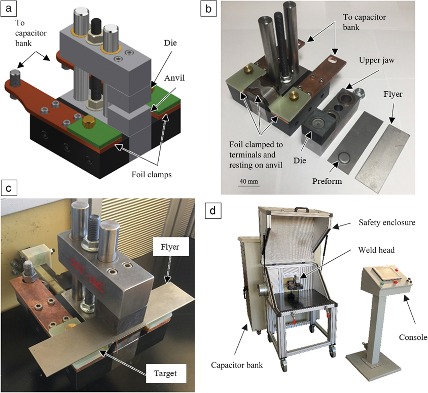
A model of the VFAW welding head, fabricated at The Ohio State University and used in this work, is shown in Figure 2a. This head was designed and built for the purpose of spot welding and flange welding with the foil designs shown in Figure 1. The various parts of the welding head can be seen in Figure 2b. The anvil and die blocks of this fixture can be replaced with alternate designs or be simply replaced due to wear or damage. The upper jaw of this fixture slides vertically along two shafts to facilitate placement, provide good alignment of the stack, and accommodate various thicknesses of materials to be welded.
Welding apparatus used for vaporizing foil actuator welding. (a) Design of the weld head; (b) various parts of the weld head; (c) arrangement for welding in lap shear configuration; and (d) complete welding system.

In operation, a stack consisting of the foil, flyer, and target are inserted into the jaws of the fixture, and the stack is simply held by light compression from the nut, as shown in Figure 2c. The foil actuator is insulated from the workpieces, anvil, and die blocks using insulating polymer tape. Figure 2d shows the complete system with the welding head, capacitor bank, safety enclosure, and control pedestal. The welding head itself weighs 5.3 kg. The enclosure maintains safe operation with noise levels under 90 dBA, which is close to the maximum allowed noise level of 85 dBA for an eight-hour continuous shift without wearing a hearing protection device.10 The purpose-built capacitor bank has a maximum discharge energy of 4.2 kJ and a 7 µs short circuit rise time.
Welding experiments
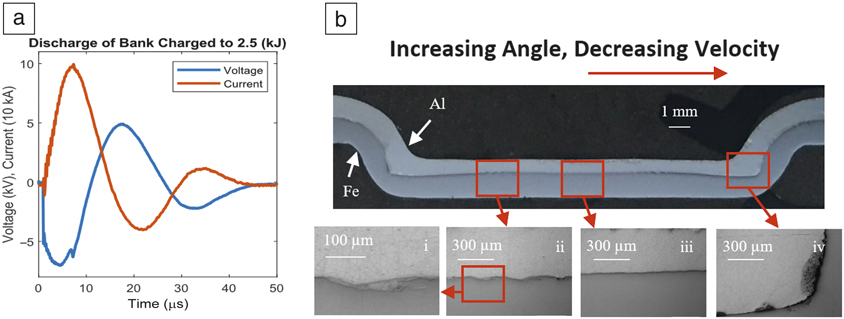
Figure 3a shows the temporal evolution of current and voltage discharge from the capacitor bank for a VFAW experiment.Reference Kapil, Lee, Vivek, Cooper, Hetrick and Daehn8 The foil burst temporarily breaks the circuit and the immediate sharp drop in current results in a spike in the voltage, which in turn, is the indicator of the burst event. Sufficient plasma remains such that a nearly damped-sine plot remains in this case.
Typical diagnostics and characterization.Reference Kapil, Lee, Vivek, Cooper, Hetrick and Daehn8 (a) Temporal evolution of current and voltage depicting rapid variation in current and voltage and a spike in voltage indicating the time of foil vaporization, and (b) hierarchical structure of the Al-Fe welded interface showing (i) material mixing in vortices of waves (ii) along the interface. (iii) The center of the weld has a flat, typically unwelded region due to a flat impact. Impact angle increases and velocity decreases with distance away from the center. (iv) The jetted material is collected in the corner of the weld as shown in this part.

Shown in Figure 3b is the typical microstructure of the weld created with a dimpled target sheet. It shows that the impact welded interface is heterogeneous and includes bonded and unbonded areas. The center of the weld, Figure 3b(iii), with just normal impact produces an unbonded area. Moving outward, Figure 3b(i–ii), the impact angle increases and a wavy strong bond area is produced, resulting in jetting, which collects at the corners, Figure 3b(iv), that are also unwelded. Despite the presence of defects, such as voids and intermetallic compounds, the welds made with VFAW have high strength and fatigue resistance.Reference Kapil, Lee, Vivek, Bockbrader, Abke and Daehn11 The point about high strength is discussed next through examples of VFA welded aluminum-steel joints, all of which fail outside the welded region upon mechanical testing. In terms of fatigue resistance of the joints, a study on steel-steel as well aluminum-aluminum welds showed that, as is the case with the fusion weld, the cyclic limits for failure scale with static failure loads.Reference Kapil, Lee, Vivek, Bockbrader, Abke and Daehn11 For example, when the static strengths of a resistance spot weld and a VFAW joint made with aluminum sheets were 6000 N and 21,000 N, respectively, their cyclic failure load limits with 1,000,000 cycles were approximately 1100 N and 3000 N. Detailed characterization of the welded microstructures joined in this manner are available elsewhere.Reference Sridharan, Poplawsky, Vivek, Bhattacharya, Guo, Meyer, Mao, Lee and Daehn12
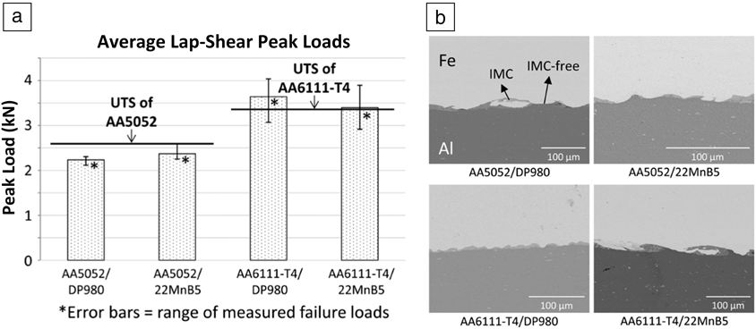
Figure 4 depicts the results of microstructure characterization and mechanical testing of four high-strength aluminum alloys (AAs) and steel combinations relevant to the automotive industry: AA5052-dual phase (DP) 980 steel, AA5052-22MnB5 (boron) steel, AA6111-DP980, and AA6111-boron steel.Reference Liu, Vivek, Presley and Daehn13 In Figure 4b, micrographs of the lap shear samples show that most of the interface is free of intermetallic compounds (labeled IMC), which are deleterious to the strength of the weld, and any intermetallic compounds that do form are usually in small and discontinuous zones. Some characteristic waviness of the impact welded interface is also seen in each case. During lap shear testing, all welds were strong enough to force the failure location to occur in the base metal. Joint efficiency, defined as the ratio of the strengths of the joint and the base metal, was close to 100% in all cases. Strength is usually controlled by the geometric configuration and thinning of the flyer sheet rather than material softening due to a heat-affected zone, which is practically absent in VFAW.
Characterization of dissimilar welds of high-strength aluminum alloys (AA; magnesium, silicon-based AA6061 and magnesium-based AA5052) to dual-phase (DP) and boron steels. (a) Results of lap shear testing of impact welded high-strength aluminum-steel combinations compared with base metal (aluminum alloy) strength, represented by horizontal lines. The welded samples had peak failure loads similar to those of base aluminum alloys, and (b) corresponding microstructures of the impact welded interfaces shown by scanning electron micrographs taken in backscatter mode.Reference Liu, Vivek, Presley and Daehn13 Note: IMC, intermetallic compound; UTS, ultimate tensile strength; T4, a temper designation indicating solutionized, quenched, and naturally aged material history.

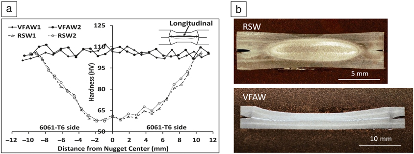
The comparison of an impact weld and a fusion (resistance spot) weld (between pairs of 2-mm 6061-T6 sheets), with respect to the heat-affected zone is depicted in Figure 5.Reference Kapil, Lee, Vivek, Cooper, Hetrick and Daehn8 The composition of the aluminum alloy can be found in the reference. Vickers microhardness traverses were conducted with a square-based pyramid diamond indentor operating at a load of 0.98 N and a dwell time of 15 s. The traverses across the weld nugget of the resistance spot welded sample shows an almost 50% decrease in strength at the nugget center as compared to the base metal due to overaging of the material caused by heat effects from the resistance spot welding process. However, for the VFAW sample, there is no change in the hardness as it is a cold-welding process and microstructural changes are due to strain hardening. Although this is a similar material weld between two sheets of 6061 grade aluminum (containing magnesium and silicon), similar observations are anticipated for dissimilar joints.
Difference between fusion and impact welds (a) longitudinal microhardness traverses across welded 6061-T6 (magnesium- and silicon-based, artificially aged to peak hardness) Al sheets indicating severe weakening of the fusion welded zone, resistance spot welding (RSW), as compared to the impact welded zone, vaporizing foil actuator welding (VFAW), which shows no reduction in hardness. (Inset) The horizontal line indicates the line along which microhardness of various points in the weld nugget were measured. RSW1 and RSW2, and VFAW1 and VFAW2 are created under two sets of the same conditions for RSW and VFAW, respectively, and (b) optical micrographs of RSW and VFAW samples. The material in and around the weld nugget is clearly more affected in the RSW sample.Reference Kapil, Lee, Vivek, Cooper, Hetrick and Daehn8

Summary
The VFAW process can be carried out using lightweight and simple fixtures, and a small energy capacitor bank. The process has been used to weld a wide variety of material combinations, including automotive grade high-strength aluminum alloys and steel. Joint efficiency close to 100% can be achieved if the weld configuration is appropriately designed. The process does not produce heat-affected zones and is, therefore, useful for welding not only dissimilar material combinations, but also similar combinations of advanced, engineered materials. Additional work has been performed on aluminum-based aerospace alloys, such as 6061 and 7075 (silicon magnesium and zinc magnesium-based alloys) as well as nickel- and titanium-based superalloys, and the test results will be published in the future. The ability of VFAW to produce high-quality welds between dissimilar materials without the need of a third body, such as a fastener or an adhesive is unique and provides a great opportunity for designers to create stronger, lighter, multimaterial assemblies. The process does need further maturation and would see first use in high-value and niche applications where existing joining methods either cannot be utilized or are providing only a subpar solution.
Acknowledgments
Support for this work comes from the US Department of Energy under Contract No. DE-EE0007813, the Ohio Development Services Agency under Grant No. GRT00043339, and the National Science Foundation under a Major Research Instrument Grant No. 1531785.

Brian P. Thurston is a graduate student in the Department of Materials Science at The Ohio State University (OSU). He received his bachelor’s degree in mechanical engineering from OSU in 2018. He was previously an undergraduate research assistant in the Impulse Manufacturing Laboratory at OSU from 2015 to 2018. He was a co-recipient of the grand prize in the LIFT Robotic Blacksmithing Challenge in 2017. His research interests include impact welding, dynamic motion control, and optical systems. Thurston can be reached by email at Thurston.56@osu.edu.

Anupam Vivek is a research scientist in the Department of Materials Science and Engineering at The Ohio State University (OSU). He received his BS degree in manufacturing science from the Indian Institute of Technology, India, and his PhD degree in materials science from OSU. He serves on the Technology Advisory Committee of the International Impulse Forming Group. He has held visiting researcher positions at the University of New Hampshire, the Technical University of Dortmund, Germany, and American Trim. He is a co-inventor of vaporizing foil actuator technology. Vivek can be reached by email at vivek.4@osu.edu.

Bhuvi Swarna Lalitha Nirudhoddi is a doctoral candidate in the Impulse Manufacturing Laboratory at The Ohio State University (OSU). She received her BS degree in aerospace engineering from Purdue University. Her research focuses on impact welding and impulse forming of high-strength aerospace alloys. She is currently investigating the mechanism of shock-based athermal stress relief in metals. In 2018, her work on impact welding was awarded first place in the AeroDef Poster Challenge. She was a co-recipient of the first prize in the LIFT Robotic Blacksmithing competition in 2017. She is the current president of the Women in Engineering Graduate Council at OSU. Nirudhoddi can be reached by email at nirudhoddi.1@osu.edu.

Glenn S. Daehn is the Mars G. Fontana Professor of Metallurgical Engineering at The Ohio State University. He received his BS degree in materials science and engineering from Northwestern University, and his MS and PhD degrees in materials science and engineering from Stanford University. His current research focuses on unconventional processing routes for high-strength lightweight materials and assemblies. He has been involved in impulse manufacturing for 30 years. His interests also include the STEM pipeline of students and manufacturing policy. He serves as Chair of the Board of Trustees of the ASM Materials Education Foundation and is on the Executive Committee of MForesight, a manufacturing think-and-do-tank. Daehn can be reached by email at Daehn.1@osu.edu.