




1 Introduction
The flow over a backward step is a canonical problem in fluid mechanics, which has been studied extensively over the years as a model problem for illustrating fluid flow over a sharp discontinuity (Morgan et al. Reference Morgan, Periaux and Thomasset1984; Chen et al. Reference Chen, Asai, Nonomura, Xi and Liu2018). Considered as a benchmark set-up for describing flow separation and reattachment phenomena, a large number of works have investigated the two-dimensional problem in incompressible viscid media, and studied passive and active means by which the separated zone may be monitored (e.g. Lai, Yue & Platzer Reference Lai, Yue and Platzer2002; Park et al. Reference Park, Jeon, Choi and Yoo2007). Other works have examined the counterpart compressible problem (as in Chow & Shih (Reference Chow and Shih1977); Bolgar, Scharnowski & Kahler (Reference Bolgar, Scharnowski and Kahler2018)), where transonic and supersonic flow velocities take place. Regardless of the magnitude of flow velocity, it has been established that fluid viscosity is essential for the occurrence of edge separation, whereas ideal (irrotational) flows exhibit attached flow profiles (King & Blood Reference King and Blood1987).
Ongoing developments in the field of micro-electro-mechanical systems (MEMS) have led to an increasing number of investigations on microfluidic flows, ubiquitously encountered in small-scale devices containing micro-channel geometries (Karniadakis, Beskok & Aluru Reference Karniadakis, Beskok and Aluru2005; Kandlikar et al. Reference Kandlikar, Li, King, Garimella and Colin2006). Motivated by the overwhelming complexity of channels networks contained in microfluidic chips (Thorsen, Maerkl & Quake Reference Thorsen, Maerkl and Quake2002), the study of heat and mass transfer phenomena in non-straight channel geometries has become the focus of several works. In the context of rarefied gas flows, these have included, among others, studies on the effects of channels bending (Sharipov & Graur Reference Sharipov and Graur2012; Liu et al. Reference Liu, Tang, Su, Wu and Zhang2018), gradual section expansion (Naris, Tantos & Valougeorgis Reference Naris, Tantos and Valougeorgis2014; Graur et al. Reference Graur, Veltzke, Meolans, Ho and Thoming2015; Hemadri, Parade & Bhandarkar Reference Hemadri, Parade, Bhandarkar and Agrawal2016; Tatsios et al. Reference Tatsios, Quesada, Rojas-Cardenas, Baldas, Colin and Valougeorgis2017) and geometrical irregularities, including sudden expansion and contraction (Agrawal, Djenidi & Antonia Reference Agrawal, Djenidi and Antonia2005; Gat, Frankel & Weihs Reference Gat, Frankel and Weihs2008; Hong, Zhen & Yang Reference Hong, Zhen and Yang2008; Varade, Agrawal & Paradeep Reference Varade, Agrawal and Paradeep2014).
In line with the above set of works, the channel flow over microscale steps has been investigated and recently reviewed (Kherbeet et al. Reference Kherbeet, Safaei, Mohammed, Salmand, Ahmed, Alawi and Al-Asadi2016). Focusing on the limit of small Knudsen ( $Kn$) numbers, several studies have applied continuum-limit models to describe and monitor the detachment and reattachment phenomena in a slightly rarefied gas (Beskok Reference Beskok2001; Baysal, Erbas & Koklu Reference Baysal, Erbas and Koklu2004; Bao & Lin Reference Bao and Lin2011). The majority of works have otherwise used the direct simulation Monte Carlo (DSMC) method to analyse the backward step flow at arbitrary Knudsen numbers. To this end, Xue et al. (Reference Xue, Xu, Wei and Wu2005) applied DSMC calculations to characterize the effect of gas rarefaction on the flow regime, and reported on sudden ‘jumps’ in the hydrodynamic fields at the step section at large
 $Kn$ conditions. Roohi, Mahdavi and co-workers (Darbandi & Roohi Reference Darbandi and Roohi2011; Mahdavi et al. Reference Mahdavi, Le, Roohi and White2014; Mahdavi & Roohi Reference Mahdavi and Roohi2015) conducted numerical simulations to analyse the effects of step temperature and gas heat transfer on the flow field. More recently, Gavasane, Agrawal & Bhandarkar (Reference Gavasane, Agrawal and Bhandarkar2018) demonstrated the occurrence of the Knudsen paradox in a micro-step channel geometry. The counterpart three-dimensional problem was earlier considered by Hsieh, Hong & Pan (Reference Hsieh, Hong and Pan2010).
A common observation in the above work is that step flow detachment is essentially a low Knudsen number phenomenon, confined to the continuum-limit and early transition regimes. With increasing  $Kn$, the detached zone diminishes and reattachment occurs closer to the step. At attached-flow conditions, pronounced hydrodynamic-field gradients appear at the step junction, and a zone of low velocity (with attached streamlines) forms in the vicinity of the step (Agrawal et al. Reference Agrawal, Djenidi and Antonia2005; Xue et al. Reference Xue, Xu, Wei and Wu2005). In several cases, step flow detachment was also reported at inlet-based Knudsen numbers as high as
 $Kn\approx 10$ (Darbandi & Roohi Reference Darbandi and Roohi2011; Mahdavi & Roohi Reference Mahdavi and Roohi2015).
As the above observations are based on DSMC computations, their scope is inevitably limited by the drawbacks of the numerical method and may benefit from direct analysis of the kinetic model. Focusing on the limit of large gas rarefaction, the primary objective of the present contribution is to provide such an insight through rigorous investigation of the free-molecular flow problem. We consider a two-dimensional micro-step set-up, and construct a steady semi-analytical solution in the free-molecular regime, for both diffuse and specular-reflecting channel walls. Arbitrary ratios are allowed between the inlet and outlet gas equilibrium conditions. Different from previous studies, the calculation highlights the distinct effects of specular and diffuse walls, leading to qualitatively disparate flow fields. Collision-free DSMC calculations are used to support the analytical results. While flow detachment (in the ‘conventional’ form of flow recirculation and reattachment) does not occur at free-molecular conditions, the results do indicate a detached zone in the vicinity of the step at sufficiently small flow velocities. The detached zone combines the step edge stagnation points with connecting flow streamlines. Notably, this result could not be effectively revealed by means of the DSMC scheme, as the simulation statistical noise obscures the flow signal at the small velocities involved. Considering finite rarefaction rates, the work characterizes the breakdown of the collisionless-flow conditions with decreasing  $Kn$, highlighting the specific effects of molecular collisions, and the consequent occurrence of step flow separation.
In the next section, the kinetic problem is stated. The free-molecular limit is analysed in § 3, followed by an outline of the DSMC algorithm in § 4. The work results, discussing the free-molecular regime and the effect of molecular collisions at high Knudsen numbers, are presented in § 5. Our conclusions are given in § 6.
2 Statement of the problem
Schematic of the micro-step channel geometry.

Consider a perfect monatomic gas passing through a two-dimensional channel with a step, as described in figure 1. The channel  $x^{\ast }$-wise length is
 $l^{\ast }=l_{u}^{\ast }+l_{d}^{\ast }$, where
 $l_{u}^{\ast }$ and
 $l_{d}^{\ast }$ denote the sizes of its left (upstream) and right (downstream) parts, respectively (hereafter, asterisks denote dimensional quantities). The step, located at
 $x^{\ast }=0$, is of length
 $h_{s}^{\ast }$, and the channel inlet (at
 $x^{\ast }=-l_{u}^{\ast }$) and outlet (at
 $x^{\ast }=l_{d}^{\ast }$) widths are
 $h_{in}^{\ast }$ and
 $h_{out}^{\ast }$, respectively. It is assumed that the inlet and outlet channel sections are connected to equilibrium-set reservoirs, where the gas is maintained at thermodynamic
 $(\unicode[STIX]{x1D70C}_{in}^{\ast },T_{in}^{\ast })$ and
 $(\unicode[STIX]{x1D70C}_{out}^{\ast },T_{out}^{\ast })$ equilibrium densities and temperatures, respectively. Gas particles entering the inlet and outlet sections are then distributed according to the equilibrium Maxwellian distributions
 $$\begin{eqnarray}f_{in}^{\ast }(\boldsymbol{c}^{\ast }\boldsymbol{\cdot }\hat{\boldsymbol{x}}^{\ast }>0)=\frac{\unicode[STIX]{x1D70C}_{in}^{\ast }}{\unicode[STIX]{x03C0}^{3/2}U_{th_{in}}^{\ast 3}}\exp \!\left[-\frac{c^{\ast 2}}{U_{th_{in}}^{\ast 2}}\right]\quad \text{and}\quad f_{out}^{\ast }(\boldsymbol{c}^{\ast }\boldsymbol{\cdot }\hat{\boldsymbol{x}}^{\ast }<0)=\frac{\unicode[STIX]{x1D70C}_{out}^{\ast }}{\unicode[STIX]{x03C0}^{3/2}U_{th_{out}}^{\ast 3}}\exp \!\left[-\frac{c^{\ast 2}}{U_{th_{out}}^{\ast 2}}\right]\!,\end{eqnarray}$$
where  $U_{th_{in}}^{\ast }=\sqrt{2{\mathcal{R}}^{\ast }T_{in}^{\ast }}$ and
 $U_{th_{out}}^{\ast }=\sqrt{2{\mathcal{R}}^{\ast }T_{out}^{\ast }}$ denote the gas mean thermal speeds at the inlet and outlet reservoirs, respectively, and
 ${\mathcal{R}}^{\ast }$ marks the specific gas constant. Additionally,
 $\boldsymbol{c}^{\ast }=(c_{x}^{\ast },c_{y}^{\ast },c_{z}^{\ast })$ denotes the vector of molecular velocities, and
 $\hat{\boldsymbol{x}}^{\ast }$ is a unit vector in the
 $x^{\ast }$-direction. Strictly, equation (2.1) should be valid only at free-molecular conditions, whereas end-effect corrections (resulting in an effective correction to the channel length) need to be taken into account at finite Knudsen numbers (see, e.g. Pantazis, Valougeorgis & Sharipov (Reference Pantazis, Valougeorgis and Sharipov2013)). To facilitate the discussion, we nevertheless apply the conditions (2.1) also at finite Knudsen numbers, as the focus of our work is on collisionless- and near-collisionless-flow regimes. Gas–surface interactions of the gas particles with the channel boundaries are modelled via the Maxwell boundary condition (Sone Reference Sone2007),
 $$\begin{eqnarray}f(x_{b}^{\ast },y_{b}^{\ast },\boldsymbol{c}^{\ast }\boldsymbol{\cdot }\hat{\boldsymbol{n}}^{\ast }>0)=\unicode[STIX]{x1D6FC}~\frac{\unicode[STIX]{x1D70C}_{b}^{\ast }(x_{b}^{\ast },y_{b}^{\ast })}{\unicode[STIX]{x03C0}^{3/2}U_{th_{b}}^{\ast 3}}\exp \left[-\frac{c^{\ast 2}}{U_{th_{b}}^{\ast 2}}\right]+(1-\unicode[STIX]{x1D6FC})f(x_{b}^{\ast },y_{b}^{\ast },\boldsymbol{c}^{\ast }-2(\boldsymbol{c}^{\ast }\boldsymbol{\cdot }\hat{\boldsymbol{n}}^{\ast })\hat{\boldsymbol{n}}^{\ast }),\end{eqnarray}$$
where the relative  $\unicode[STIX]{x1D6FC}$ and
 $(1-\unicode[STIX]{x1D6FC})$ parts of the gas molecules are emitted diffusely and specularly, respectively, at each point
 $(x_{b}^{\ast },y_{b}^{\ast })$ along the boundaries. Here,
 $\hat{\boldsymbol{n}}^{\ast }$ denotes a unit normal vector directed into the gas,
 $\unicode[STIX]{x1D70C}_{b}^{\ast }(x_{b}^{\ast },y_{b}^{\ast })$ is a yet unknown function associated with the mass flux of particles emitted from the boundary and
 $U_{th_{b}}^{\ast }=\sqrt{2{\mathcal{R}}^{\ast }T_{b}^{\ast }}$ is the mean thermal speed based on the boundary temperature
 $T_{b}^{\ast }$. The channel solid boundaries are assumed isothermal and with the common inlet reservoir temperature
 $T_{in}^{\ast }$. Consideration of different wall temperatures, as studied in Mahdavi et al. (Reference Mahdavi, Le, Roohi and White2014) and Mahdavi & Roohi (Reference Mahdavi and Roohi2015), may be readily carried out, but is not followed here to simplify presentation (see § 6).
To render the problem dimensionless, we scale the position by the inlet width  $h_{in}^{\ast }$, the velocity by
 $U_{th_{in}}^{\ast }$, and the density and temperature by
 $\unicode[STIX]{x1D70C}_{in}^{\ast }$ and
 $T_{in}^{\ast }$, respectively. The system description is then governed by the channel reduced geometrical measures
 $$\begin{eqnarray}l,\quad l_{u}\quad \text{and}\quad h_{s}\end{eqnarray}$$
of its total length, upstream-part size (with  $l_{d}=l-l_{u}$ fixed thereby) and step width, together with the outlet reservoir properties
 $$\begin{eqnarray}\unicode[STIX]{x1D70C}_{out}\quad \text{and}\quad T_{out}\end{eqnarray}$$
of the gas density and temperature, respectively. In what follows, we study the flow field in the channel at rarefied flow conditions, focusing on the limit of high rarefaction rates. Towards this end, we assume steady flow conditions, and start by analysing the free-molecular limit of the problem. The analytical results are then compared with DSMC predictions, to validate the collisionless description, test the breakdown of the free-molecular regime and assess the effect of molecular collisions. No restrictions are placed on the values of  $\unicode[STIX]{x1D70C}_{out}$ and
 $T_{out}$, which allows for the analysis of the flow field at arbitrary pressure and temperature differences between the channel inlet and outlet reservoirs.
3 The free-molecular limit
Considering two-dimensional and steady conditions, and neglecting the effect of molecular collisions, the kinetic problem in the free-molecular regime is governed by the collisionless Boltzmann equation,
 $$\begin{eqnarray}c_{x}\frac{\unicode[STIX]{x2202}f}{\unicode[STIX]{x2202}x}+c_{y}\frac{\unicode[STIX]{x2202}f}{\unicode[STIX]{x2202}y}=0,\end{eqnarray}$$
stating that the probability density function  $f(x,y,\boldsymbol{c})$ is constant along ‘free flight’ (constant velocity) trajectories of a particle, and varies with changes in
 $(c_{x},c_{y})$. Since molecular collisions are absent, such variations may occur only due to surface–particle interactions, prescribed by the scaled form of (2.2):
 $$\begin{eqnarray}f(x_{b},y_{b},\boldsymbol{c}\boldsymbol{\cdot }\hat{\boldsymbol{n}}>0)=\unicode[STIX]{x1D6FC}\frac{\unicode[STIX]{x1D70C}_{b}(x_{b},y_{b})}{\unicode[STIX]{x03C0}^{3/2}}\exp [-c^{2}]+(1-\unicode[STIX]{x1D6FC})f(x_{b},y_{b},\boldsymbol{c}-2(\boldsymbol{c}\boldsymbol{\cdot }\hat{\boldsymbol{n}})\hat{\boldsymbol{n}}).\end{eqnarray}$$
The solid wall condition (3.2) is supplemented by the non-dimensional counterpart of (2.1),
 $$\begin{eqnarray}\displaystyle \left.\begin{array}{@{}c@{}}\displaystyle f_{in}=f(x=-l_{u},0\leqslant y\leqslant 1,c_{x}>0)=\frac{1}{\unicode[STIX]{x03C0}^{3/2}}\exp [-c^{2}]\quad \text{and}\\ \displaystyle f_{out}=f(x=l_{d},-h_{s}\leqslant y\leqslant 1,c_{x}<0)=\frac{\unicode[STIX]{x1D70C}_{out}}{\unicode[STIX]{x03C0}^{3/2}T_{out}^{3/2}}\exp \left[-\frac{c^{2}}{T_{out}}\right],\end{array}\right\} & & \displaystyle\end{eqnarray}$$
prescribing the state of incoming particles at the inlet and outlet sections, respectively. The problem formulated in (3.1)–(3.3) is analysed separately for the cases of fully diffuse ( $\unicode[STIX]{x1D6FC}=1$; § 3.1) and fully specular (
 $\unicode[STIX]{x1D6FC}=0$; § 3.2) walls. These two extreme cases may be considered as limit realizations of completely accommodating and reflecting boundaries, respectively. Diffuse scattering takes place over ‘rough’ surfaces, where the colliding particles attain thermal equilibrium with the reflecting wall and evaporate accordingly. Specular interactions occur when the incident molecules collide with a solid surface and rebound elastically as if hitting a perfectly smooth wall. While none of these idealized scenarios appears to exist in reality, it is commonly accepted that wall reflections from ‘engineering’ surfaces may be described, in a variety of applications, as a combination of diffuse and specular interactions, as formulated in (3.2). The combined diffuse–specular (
 $0<\unicode[STIX]{x1D6FC}<1$) case then composes the two limits, and is therefore not considered hereafter in detail.
3.1 Diffuse-reflecting walls
Setting  $\unicode[STIX]{x1D6FC}=1$ in (3.2), the state of each gas particle in the channel is determined by its last reflection from one of the channel (free or solid) boundaries. The general solution for the problem is therefore given by
 $$\begin{eqnarray}f(x,y,\boldsymbol{c})=\frac{\widetilde{\unicode[STIX]{x1D70C}}(x,y,\boldsymbol{c})}{\unicode[STIX]{x03C0}^{3/2}\widetilde{T}^{3/2}}\exp \left[-\frac{c^{2}}{\widetilde{T}}\right],\end{eqnarray}$$
where  $\widetilde{T}$ is the prescribed temperature of the emitting boundary, and
 $\widetilde{\unicode[STIX]{x1D70C}}(x,y,\boldsymbol{c})$ is an unknown function to be determined. Given a particle position
 $(x,y)$ and its in-plane velocity vector
 $(c_{x},c_{y})$, the identity of its last emitting boundary is uniquely determined. A similar description has been applied previously to approximate the flow-field pattern obtained in a grooved channel at collisionless-flow conditions (Naris & Valougeorgis Reference Naris and Valougeorgis2007).
Calculation of  $\widetilde{\unicode[STIX]{x1D70C}}(x,y,\boldsymbol{c})$ is carried out by imposing the impermeability condition,
 $$\begin{eqnarray}\int _{\boldsymbol{c}\boldsymbol{\cdot }\hat{\boldsymbol{n}}>0}(\boldsymbol{c}\boldsymbol{\cdot }\hat{\boldsymbol{n}})f(x_{b},y_{b},\boldsymbol{c})\,\text{d}\boldsymbol{c}+\int _{\boldsymbol{c}\boldsymbol{\cdot }\hat{\boldsymbol{n}}<0}(\boldsymbol{c}\boldsymbol{\cdot }\hat{\boldsymbol{n}})f(x_{b},y_{b},\boldsymbol{c})\,\text{d}\boldsymbol{c}=0,\end{eqnarray}$$
along each of the solid channel boundaries. Here, the first and second integrals express the separate contributions of the outgoing and incoming particles to the macroscopic gas velocity normal to the wall, respectively. At a given location, incoming particles may arrive from different channel boundaries, and their respective contributions should be accordingly accounted for.
Geometrical construction of the impermeability condition at a point  $(x,-h_{s})$ along the downstream wall
 $l_{d}$. (a) A point location where the inlet section and the left part
 $-l_{u}\leqslant x\leqslant 1+l_{d}-\unicode[STIX]{x1D6E5}_{l}$ of the upper boundary are obscured. (b) A point where the lower part
 $0\leqslant y\leqslant 1-\unicode[STIX]{x1D6E5}_{in}$ of the inlet section is obscured. The points are marked by filled circles, and the dashed lines separate channel domains of particles arriving from the different boundaries. The angles
 $\unicode[STIX]{x1D6FC}_{s},\unicode[STIX]{x1D6FC}_{l},\unicode[STIX]{x1D6FC}_{out}$ and
 $\unicode[STIX]{x1D6FC}_{in}$ denote the section angles associated with each boundary.

We demonstrate the derivation of the walls impermeability conditions by detailing the calculation of the equation at the downstream wall, along which  $0\leqslant x\leqslant l_{d}$ and
 $y=-h_{s}$. Using (3.2) with
 $\unicode[STIX]{x1D6FC}=1$, the contribution of the reflected particles integral in (3.5) is
 $$\begin{eqnarray}\int _{\boldsymbol{c}\boldsymbol{\cdot }\hat{\boldsymbol{n}}>0}(\boldsymbol{c}\boldsymbol{\cdot }\hat{\boldsymbol{n}})f_{d}\,\text{d}\boldsymbol{c}=\frac{\unicode[STIX]{x1D70C}_{d}(x)}{2\sqrt{\unicode[STIX]{x03C0}}},\end{eqnarray}$$
where the subscript  $d$ denotes that the function is evaluated at a point along the downstream wall. A less straightforward calculation is required to obtain the contribution of the incoming particles (
 $\boldsymbol{c}\boldsymbol{\cdot }\hat{\boldsymbol{n}}<0$ integral) term in (3.5). Here, depending on the specific location at the wall and the channel geometry, particles may arrive from either the inlet, upper wall, outlet or step boundaries, whereas no particles are transmitted from the ‘obscured’ upstream
 $l_{u}$ surface. This is illustrated in figure 2, where the dashed lines separate channel domains of particles arriving from the different boundaries. Kinematically, these lines confine the
 $c_{x}/c_{y}$ ratio of in-plane molecular velocity components pertaining to particle emittance from each surface. Considering reflections from the upper and inlet boundaries, cases where
 $0\leqslant x\leqslant h_{s}l_{u}$ (shown in figure 2a) and
 $h_{s}l_{u}<x\leqslant l_{d}$ (depicted in figure 2b, and occurring only in channels where
 $h_{s}l_{u}<l_{d}$) should be distinguished. In the former, particles may arrive from the
 $-x/h_{s}\leqslant x\leqslant l_{d}$ interval of the upper
 $l$ boundary, marked by
 $\unicode[STIX]{x1D6E5}_{l}$, and not from the inlet section. In the latter, particles may be transmitted from the entire
 $l$ boundary and the upper
 $1-h_{s}-h_{s}l_{u}/x\leqslant y\leqslant 1$ portion of the channel inlet, denoted by
 $\unicode[STIX]{x1D6E5}_{in}$.
The particle kinematics is next followed to express the contributions of the incoming particles from each of the surfaces to the impermeability condition (3.5). For particles reflected from the outlet section, it is seen from figure 2 that  $(l_{d}-x)/(1+h_{s})\leqslant c_{x}/c_{y}<\infty$ with both
 $c_{x},c_{y}\leqslant 0$. Making use of (3.3), we find
 $$\begin{eqnarray}\displaystyle \int _{\boldsymbol{c}\boldsymbol{\cdot }\hat{\boldsymbol{n}}<0}(\boldsymbol{c}\boldsymbol{\cdot }\hat{\boldsymbol{n}})f_{out}\,\text{d}\boldsymbol{c} & = & \displaystyle \int _{-\infty }^{0}\int _{-\infty }^{((x-l_{d})/(1+h_{s}))|c_{y}|}\int _{-\infty }^{\infty }c_{y}f_{out}\,\text{d}c_{z}\,\text{d}c_{x}\,\text{d}c_{y}\nonumber\\ \displaystyle & = & \displaystyle \frac{\unicode[STIX]{x1D70C}_{out}\sqrt{T_{out}}}{4\sqrt{\unicode[STIX]{x03C0}}}\left(\frac{l_{d}-x}{\sqrt{(1+h_{s})^{2}+(l_{d}-x)^{2}}}-1\right).\end{eqnarray}$$
For particles arriving from the step wall,  $x/h_{s}\leqslant |c_{x}/c_{y}|<\infty$ with
 $c_{x}\geqslant 0$ and
 $c_{y}\leqslant 0$. Using (3.4), the integral contribution in this case is given by
 $$\begin{eqnarray}\int _{\boldsymbol{c}\boldsymbol{\cdot }\hat{\boldsymbol{n}}<0}(\boldsymbol{c}\boldsymbol{\cdot }\hat{\boldsymbol{n}})f_{s}\,\text{d}\boldsymbol{c}=\frac{1}{\unicode[STIX]{x03C0}^{3/2}}\int _{-\infty }^{0}\int _{(x/h_{s})|c_{y}|}^{\infty }\int _{-\infty }^{\infty }c_{y}\unicode[STIX]{x1D70C}_{s}\left(\left|\frac{c_{y}}{c_{x}}\right|x-h_{s}\right)\exp [-c^{2}]\,\text{d}c_{z}\,\text{d}c_{x}\,\text{d}c_{y},\end{eqnarray}$$
where the argument in  $\unicode[STIX]{x1D70C}_{s}=\unicode[STIX]{x1D70C}_{s}(y)$ relates each
 $x$-location along
 $l_{d}$ with a point
 $y$ along the step for a particle arriving with a velocity ratio
 $c_{x}/c_{y}$. Appropriate change of variables and
 $c_{y},c_{z}$ integrations then yield
 $$\begin{eqnarray}\int _{\boldsymbol{c}\boldsymbol{\cdot }\hat{\boldsymbol{n}}<0}(\boldsymbol{c}\boldsymbol{\cdot }\hat{\boldsymbol{n}})f_{s}\,\text{d}\boldsymbol{c}=-\frac{x}{4\sqrt{\unicode[STIX]{x03C0}}}\int _{-h_{s}}^{0}\frac{(p+h_{s})\unicode[STIX]{x1D70C}_{s}(p)}{[(p+h_{s})^{2}+x^{2}]^{3/2}}\,\text{d}p.\end{eqnarray}$$
Considering to the upper  $l$ boundary for the case illustrated in figure 2(a), it is observed that
 $(x-l_{d})/(1+h_{s})\leqslant c_{x}/|c_{y}|<x/h_{s}$, with
 $-\infty <c_{x}<\infty$ and
 $-\infty <c_{y}\leqslant 0$. Subsequently,
 $$\begin{eqnarray}\displaystyle & & \displaystyle \int _{\boldsymbol{c}\boldsymbol{\cdot }\hat{\boldsymbol{n}}<0}(\boldsymbol{c}\boldsymbol{\cdot }\hat{\boldsymbol{n}})f_{l}\,\text{d}\boldsymbol{c}=\frac{1}{\unicode[STIX]{x03C0}^{3/2}}\nonumber\\ \displaystyle & & \displaystyle \quad \times \int _{-\infty }^{0}\int _{((x-l_{d})/(1+h_{s}))|c_{y}|}^{(x/h_{s})|c_{y}|}\int _{-\infty }^{\infty }c_{y}\unicode[STIX]{x1D70C}_{l}\left(x-\frac{c_{x}}{|c_{y}|}(1+h_{s})\right)\exp [-c^{2}]\,\text{d}c_{z}\,\text{d}c_{x}\,\text{d}c_{y},\nonumber\end{eqnarray}$$
where a different change of variables and  $c_{y},c_{z}$ integrations yield
 $$\begin{eqnarray}\int _{\boldsymbol{c}\boldsymbol{\cdot }\hat{\boldsymbol{n}}<0}(\boldsymbol{c}\boldsymbol{\cdot }\hat{\boldsymbol{n}})f_{l}\,\text{d}\boldsymbol{c}=-\frac{(1+h_{s})^{2}}{4\sqrt{\unicode[STIX]{x03C0}}}\int _{-x/h_{s}}^{l_{d}}\frac{\unicode[STIX]{x1D70C}_{l}(p)}{[(1+h_{s})^{2}+(x-p)^{2}]^{3/2}}\,\text{d}p.\end{eqnarray}$$
For the case shown in figure 2(b), the same expression holds for the  $l$-surface, yet with the lower integration limit
 $-x/h_{s}$ replaced by
 $-l_{u}$. Using (3.3), the additional contribution of the inlet section between
 $h_{s}l_{u}<x\leqslant l_{d}$ is
 $$\begin{eqnarray}\displaystyle \int _{\boldsymbol{c}\boldsymbol{\cdot }\hat{\boldsymbol{n}}<0}(\boldsymbol{c}\boldsymbol{\cdot }\hat{\boldsymbol{n}})f_{in}\,\text{d}\boldsymbol{c} & = & \displaystyle \int _{-\infty }^{0}\int _{((x+l_{u})/(1+h_{s}))|c_{y}|}^{(x/h_{s})|c_{y}|}\int _{-\infty }^{\infty }c_{y}f_{in}\,\text{d}c_{z}\,\text{d}c_{x}\,\text{d}c_{y}\nonumber\\ \displaystyle & = & \displaystyle \frac{1}{4\sqrt{\unicode[STIX]{x03C0}}}\left(\frac{x+l_{u}}{\sqrt{(1+h_{s})^{2}+(x+l_{u})^{2}}}-\frac{x}{\sqrt{h_{s}^{2}+x^{2}}}\right).\end{eqnarray}$$
Summing equations (3.6)–(3.9) in (3.5), we obtain the impermeability condition along  $0\leqslant x\leqslant h_{s}l_{u}$
 $$\begin{eqnarray}\displaystyle & & \displaystyle 2\unicode[STIX]{x1D70C}_{d}(x)-x\int _{-h_{s}}^{0}\frac{(p+h_{s})\unicode[STIX]{x1D70C}_{s}(p)\,\text{d}p}{[(p+h_{s})^{2}+x^{2}]^{3/2}}-(1+h_{s})^{2}\int _{-x/h_{s}}^{l_{d}}\frac{\unicode[STIX]{x1D70C}_{l}(p)\,\text{d}p}{[(1+h_{s})^{2}+(x-p)^{2}]^{3/2}}\nonumber\\ \displaystyle & & \displaystyle \quad =\unicode[STIX]{x1D70C}_{out}\sqrt{T_{out}}\left(1-\frac{l_{d}-x}{\sqrt{(1+h_{s})^{2}+(l_{d}-x)^{2}}}\right),\end{eqnarray}$$
whereas for  $h_{s}l_{u}\leqslant x\leqslant l_{d}$
 $$\begin{eqnarray}\displaystyle & & \displaystyle 2\unicode[STIX]{x1D70C}_{d}(x)-x\int _{-h_{s}}^{0}\frac{(p+h_{s})\unicode[STIX]{x1D70C}_{s}(p)\,\text{d}s}{[(p+h_{s})^{2}+x^{2}]^{3/2}}-(1+h_{s})^{2}\int _{-l_{u}}^{l_{d}}\frac{\unicode[STIX]{x1D70C}_{l}(p)\,\text{d}p}{[(1+h_{s})^{2}+(x-p)^{2}]^{3/2}}\nonumber\\ \displaystyle & & \displaystyle \quad =\frac{x}{\sqrt{x^{2}+h_{s}^{2}}}-\frac{l_{u}+x}{\sqrt{(1+h_{s})^{2}+(x+l_{u})^{2}}}+\unicode[STIX]{x1D70C}_{out}\sqrt{T_{out}}\left(1-\frac{l_{d}-x}{\sqrt{(1+h_{s})^{2}+(l_{d}-x)^{2}}}\right).\nonumber\\ \displaystyle & & \displaystyle\end{eqnarray}$$
Following similar arguments, the impermeability conditions at all other solid walls are derived. Skipping the technical details for brevity, the equations obtained along the lower upstream ( $-l_{u}\leqslant x\leqslant 0,y=0$) and step (
 $x=0,-h_{s}\leqslant y<0$) walls are
 $$\begin{eqnarray}2\unicode[STIX]{x1D70C}_{u}(x)-\int _{-l_{u}}^{l_{d}}\frac{\unicode[STIX]{x1D70C}_{l}(s)\,\text{d}s}{[1+(x-s)^{2}]^{3/2}}=1-\frac{l_{u}+x}{\sqrt{1+(x+l_{u})^{2}}}+\unicode[STIX]{x1D70C}_{out}\sqrt{T_{out}}\left(1-\frac{l_{d}-x}{\sqrt{1+(l_{d}-x)^{2}}}\right)\end{eqnarray}$$
and
 $$\begin{eqnarray}\displaystyle & & \displaystyle 2\unicode[STIX]{x1D70C}_{s}(y)-(y+h_{s})\int _{0}^{l_{d}}\frac{s\unicode[STIX]{x1D70C}_{d}(s)\,\text{d}s}{[s^{2}+(y+h_{s})^{2}]^{3/2}}+(y-1)\int _{0}^{l_{d}}\frac{s\unicode[STIX]{x1D70C}_{l}(s)\,\text{d}s}{[s^{2}+(1-y)^{2}]^{3/2}}\nonumber\\ \displaystyle & & \displaystyle \quad =\unicode[STIX]{x1D70C}_{out}\sqrt{T_{out}}\left(\frac{y+h_{s}}{\sqrt{l_{d}^{2}+(y+h_{s})^{2}}}+\frac{1-y}{\sqrt{l_{d}^{2}+(1-y)^{2}}}\right),\end{eqnarray}$$
respectively. Along the upper ( $y=1$) wall, the cases
 $-l_{u}\leqslant x<-l_{d}/h_{s}$ (where no particles arrive from either the step or
 $l_{d}$ walls, occurring in channels where
 $l_{d}/h_{s}<l_{u}$),
 $-l_{d}/h_{s}\leqslant x\leqslant 0$ (where the step surface is obscured) and
 $0<x\leqslant l_{d}$ (where particles arrive from all walls) should be treated separately. For the
 $-l_{u}\leqslant x<-l_{d}/h_{s}$ and
 $-l_{d}/h_{s}\leqslant x\leqslant 0$ intervals, the impermeability conditions read
 $$\begin{eqnarray}\displaystyle -2\unicode[STIX]{x1D70C}_{l}(x)+\int _{-l_{u}}^{0}\frac{\unicode[STIX]{x1D70C}_{u}(p)\,\text{d}p}{[1+(x-p)^{2}]^{3/2}}=-1+\frac{l_{u}+x}{\sqrt{1+(x+l_{u})^{2}}}-\unicode[STIX]{x1D70C}_{out}\sqrt{T_{out}}\left(1+\frac{x}{\sqrt{1+x^{2}}}\right) & & \displaystyle \nonumber\end{eqnarray}$$
and
 $$\begin{eqnarray}\displaystyle & & \displaystyle -2\unicode[STIX]{x1D70C}_{l}(x)+\int _{-l_{u}}^{0}\frac{\unicode[STIX]{x1D70C}_{u}(p)\,\text{d}p}{[1+(x-p)^{2}]^{3/2}}+(1+h_{s})^{2}\int _{-xh_{s}}^{l_{d}}\frac{\unicode[STIX]{x1D70C}_{d}(p)\,\text{d}p}{[(1+h_{s})^{2}+(x-p)^{2}]^{3/2}}\nonumber\\ \displaystyle & & \displaystyle \quad =-1+\frac{l_{u}+x}{\sqrt{1+(x+l_{u})^{2}}}-\unicode[STIX]{x1D70C}_{out}\sqrt{T_{out}}\left(1-\frac{l_{d}-x}{\sqrt{(1+h_{s})^{2}+(l_{d}-x)^{2}}}\right),\end{eqnarray}$$
respectively, whereas along  $0<x\leqslant l_{d}$:
 $$\begin{eqnarray}\displaystyle & & \displaystyle -2\unicode[STIX]{x1D70C}_{l}(x)+\int _{-l_{u}}^{0}\frac{\unicode[STIX]{x1D70C}_{u}(p)\,\text{d}p}{[1+(x-p)^{2}]^{3/2}}+x\int _{-h_{s}}^{0}\frac{(1-p)\unicode[STIX]{x1D70C}_{s}(p)\,\text{d}p}{[(1-p)^{2}+x^{2}]^{3/2}}\nonumber\\ \displaystyle & & \displaystyle \qquad +\,(1+h_{s})^{2}\int _{0}^{l_{d}}\frac{\unicode[STIX]{x1D70C}_{d}(p)\,\text{d}p}{[(1+h_{s})^{2}+(x-p)^{2}]^{3/2}}\nonumber\\ \displaystyle & & \displaystyle \quad =-1+\frac{l_{u}+x}{\sqrt{1+(x+l_{u})^{2}}}-\unicode[STIX]{x1D70C}_{out}\sqrt{T_{out}}\left(1-\frac{l_{d}-x}{\sqrt{(1+h_{s})^{2}+(l_{d}-x)^{2}}}\right).\end{eqnarray}$$
Conditions (3.11)–(3.16) form a set of coupled integral equations for the boundaries density fluxes  $\unicode[STIX]{x1D70C}_{u}(x),\unicode[STIX]{x1D70C}_{s}(y),\unicode[STIX]{x1D70C}_{d}(x)$ and
 $\unicode[STIX]{x1D70C}_{l}(x)$, where the inlet and outlet section contributions serve as non-homogeneous forcing terms. In the case where the inlet and outlet reservoirs are kept at the same conditions,
 $\unicode[STIX]{x1D70C}_{out}=T_{out}=1$, the uniform
 $\unicode[STIX]{x1D70C}_{u}(x)=\unicode[STIX]{x1D70C}_{s}(y)=\unicode[STIX]{x1D70C}_{d}(x)=\unicode[STIX]{x1D70C}_{l}(x)=1$ solution is satisfied. For any non-trivial combination of
 $\unicode[STIX]{x1D70C}_{out}$ and
 $T_{out}$, the equations are solved numerically by discretizing the fluxes along the boundaries. To this end, the fluxes are represented by their discrete values at equally spaced points along the walls, and the integral terms are evaluated using Simpson’s rule. This yields a system of coupled non-homogeneous algebraic equations which are solved numerically. Converged results were obtained with a scaled discretization step of
 ${\approx}10^{-3}$ along the boundaries. This, nevertheless, required a minor computational effort compared with the numerical DSMC computations described in § 4.
Division of the channel domain into zones affected by the different boundaries at different locations. The point locations are denoted by filled circles and the channel subdomains I, II and III are distinguished as referred to in the text. The dashed lines separate channel zones of particles arriving from the different boundaries, with  $\unicode[STIX]{x1D6FC}_{u},\unicode[STIX]{x1D6FC}_{s},\unicode[STIX]{x1D6FC}_{d},\unicode[STIX]{x1D6FC}_{l},\unicode[STIX]{x1D6FC}_{out}$ and
 $\unicode[STIX]{x1D6FC}_{in}$ marking the sections associated with each boundary.

Having calculated the fluxes, the probability density function in (3.4) is obtained, and the hydrodynamic fields may be calculated via appropriate quadratures over the velocity space. Specifically, the density  $\unicode[STIX]{x1D70C}$, the
 $x$- and
 $y$-velocity components
 $u_{x}$ and
 $u_{y}$ and the pressure
 $p$, are given by (Sone Reference Sone2007)
 $$\begin{eqnarray}\displaystyle \hspace{-5.0pt}\left.\begin{array}{@{}c@{}}\displaystyle \unicode[STIX]{x1D70C}(x,y)=\int _{-\infty }^{\infty }f\,\text{d}\boldsymbol{c},\quad u_{x}(x,y)=\frac{1}{\unicode[STIX]{x1D70C}(x,y)}\int _{-\infty }^{\infty }c_{x}f\,\text{d}\boldsymbol{c},\quad u_{y}(x,y)=\frac{1}{\unicode[STIX]{x1D70C}(x,y)}\int _{-\infty }^{\infty }c_{y}f\,\text{d}\boldsymbol{c},\\ \displaystyle \text{and}\quad p(x,y)=\frac{2}{3}\int _{-\infty }^{\infty }[(c_{x}-u_{x})^{2}+(c_{y}-u_{y})^{2}+c_{z}^{2}]\,f\,\text{d}\boldsymbol{c},\end{array}\right\} & & \displaystyle \nonumber\\ \displaystyle & & \displaystyle\end{eqnarray}$$
whereas the temperature  $T=p/\unicode[STIX]{x1D70C}$, in accordance with the gas equation of state. At each
 $(x,y)$ location, the above integrations should average the contributions of the particles arriving from the various boundaries, in accordance with the channel geometry. Similarly to the calculation of the boundary fluxes, particles may arrive at a given point from only part of the channel boundaries, while other parts are obscured. This is illustrated by figure 3, where the channel is divided into three zones – namely, the upstream zone I (
 $-l_{u}\leqslant x\leqslant 0$ and
 $0\leqslant y\leqslant 1$), the downstream zone II (
 $0<x\leqslant l_{d}$ and
 $0\leqslant y\leqslant 1$) and the step zone III (
 $0\leqslant x\leqslant l_{d}$ and
 $-h_{s}\leqslant y<0$). While particles arrive at all points in zone II from any of the boundaries, the step and part (or all) of the
 $l_{d}$ wall are obscured in zone I, as shown by figure 3(a). In zone III, no particles may arrive directly from the upstream
 $l_{u}$ wall, and cases where the upper
 $l$ and inlet boundaries are totally or partially obscured should be distinguished, as illustrated in figure 3(b). The integrations specified in (3.17), for which details are skipped for brevity, should be carried out in accordance with the above geometrical restrictions, to yield the required
 $(x,y)$ dependencies of the hydrodynamic fields.
3.2 Specular-reflecting walls
In qualitative difference from the diffuse-scattering ( $\unicode[STIX]{x1D6FC}=1$) case, the macroscopic impermeability conditions are trivially satisfied for a specular-reflecting wall (
 $\unicode[STIX]{x1D6FC}=0$ in (3.2)), where the particles undergo mirror-like reflections with the value of the probability density function conserved. The particles in the channel may acquire either the inlet or outlet Maxwellian distribution (see (3.3)), and the problem solution reduces to distinguishing, at each
 $(x,y)$ location, between the distributions, based on the direction of the in-plane
 $(c_{x},c_{y})$ velocity vector of the particle.
Considering the upstream ( $x\leqslant 0$) part of the channel, it is clear that
 $$\begin{eqnarray}\displaystyle f(x\leqslant 0,y,\boldsymbol{c})=\left\{\begin{array}{@{}l@{}}f_{in},\quad c_{x}>0,\quad \\ f_{out},\quad c_{x}<0,\quad \end{array}\right. & & \displaystyle\end{eqnarray}$$
as particles with  $c_{x}>0$ and
 $c_{x}<0$ originate inevitably from the inlet or outlet section, respectively. Making use of (3.17) and the equation of state, the hydrodynamic fields at the channel upstream part are given by the uniform values
 $$\begin{eqnarray}\displaystyle \left.\begin{array}{@{}c@{}}\displaystyle \unicode[STIX]{x1D70C}(x\leqslant 0,y)={\textstyle \frac{1}{2}}(1+\unicode[STIX]{x1D70C}_{out}),\\ \displaystyle u_{x}(x\leqslant 0,y)=\frac{1}{\sqrt{\unicode[STIX]{x03C0}}(1+\unicode[STIX]{x1D70C}_{out})}(1-\unicode[STIX]{x1D70C}_{out}\sqrt{T_{out}}),\quad u_{y}(x\leqslant 0,y)=0,\\ \displaystyle p(x\leqslant 0,y)=\frac{1}{2}-\frac{2u_{x}}{3\sqrt{\unicode[STIX]{x03C0}}}+\frac{u_{x}^{2}}{3}+\unicode[STIX]{x1D70C}_{out}\left(\frac{T_{out}}{2}+\frac{2u_{x}\sqrt{T_{out}}}{3\sqrt{\unicode[STIX]{x03C0}}}+\frac{u_{x}^{2}}{3}\right),\end{array}\right\} & & \displaystyle\end{eqnarray}$$
and  $T(x\leqslant 0,y)=p/\unicode[STIX]{x1D70C}$, indicating a uniform one-dimensional flow in the
 $x$-direction. As will be illustrated in § 5 (see figures 5 and 6), this is markedly different from the diffuse wall set-up, where non-uniform two-dimensional flows occur at
 $x\leqslant 0$.
The particle sorting and consequent calculation of the hydrodynamic fields become less straightforward in the downstream  $x>0$ part of the channel. While particles with
 $c_{x}<0$ originate solely from the outlet reservoir (and thus acquire
 $f=f_{out}$), those with
 $c_{x}>0$ may arrive from either the inlet or outlet boundary. Here, the step wall acts as a ‘reflecting source’ for particles originating from the outlet section, by reversing the sign of their
 $x$-velocity component. It is this kinematic constraint that results in the non-uniformity and two-dimensionality of the flow field for
 $x>0$, as calculated below.
To track the origin of a  $c_{x}>0$ particle located at
 $(x_{p}>0,-h_{s}\leqslant y_{p}\leqslant 1)$, its trajectory should be followed backwards to the section
 $x=0$, where it has either passed through
 $0<y<1$ (acquiring
 $f=f_{in}$), or was emitted from the step
 $-h_{s}<y<0$ wall (and thus originated from the outlet section with
 $f=f_{out}$). At first, particles arriving ‘directly’ at
 $(x_{p},y_{p})$ from
 $x=0$ without colliding with the upper (
 $y=1$) or lower (
 $y=-h_{s}$) wall are distinguished through
 $$\begin{eqnarray}\displaystyle f(x\leqslant 0,y,\boldsymbol{c})=\left\{\begin{array}{@{}l@{}}f_{in},\quad (y_{p}-1)c_{x}/x_{p}\leqslant c_{y}\leqslant y_{p}c_{x}/x_{p},\quad \\ f_{out},\quad y_{p}c_{x}/x_{p}<c_{y}\leqslant (y_{p}+h_{s})c_{x}/x_{p},\quad \end{array}\right. & & \displaystyle\end{eqnarray}$$
which covers the  $c_{y}\in [(y_{p}-1)c_{x}/x_{p},(y_{p}+h_{s})c_{x}/x_{p}]$ interval for all
 $c_{x}>0$. Particles with
 $c_{y}<(y_{p}-1)c_{x}/x_{p}$ or
 $c_{y}>(y_{p}+h_{s})c_{x}/x_{p}$ then arrive at
 $(x_{p},y_{p})$ after one or more emissions from the upper or lower boundaries. The number
 $N_{coll}$ of these collisions is given by
 $$\begin{eqnarray}N_{coll}=\text{floor}\left\{\left|\frac{c_{y}}{c_{x}}\right|\frac{x_{LC}}{1+h_{s}}\right\},\end{eqnarray}$$
where
 $$\begin{eqnarray}\displaystyle x_{LC}=\left\{\begin{array}{@{}ll@{}}\displaystyle x-\left|\frac{c_{x}}{c_{y}}\right|(y+h_{s}),\quad & c_{y}>0\;(y_{LC}=-h_{s})\\ \displaystyle x-\left|\frac{c_{x}}{c_{y}}\right|(1-y),\quad & c_{y}<0\;(y_{LC}=1)\end{array}\right. & & \displaystyle\end{eqnarray}$$
denotes the  $x$-coordinate of the last collision of a particle with a wall (at
 $y_{LC}=-h_{s}$ or
 $y_{LC}=1$) before arriving at
 $(x_{p},y_{p})$, and
 $\text{floor}\{\cdot \}$ marks the round value of a number from below. The surface location where the particle has first collided with either of the boundaries after
 $x=0$ is then
 $$\begin{eqnarray}x_{FC}=x_{LC}-N_{coll}\left|\frac{c_{x}}{c_{y}}\right|(1+h_{s}),\end{eqnarray}$$
and the corresponding value of  $y_{FC}$ (
 $=-h_{s}$ or 1) is determined by the sign of
 $c_{y}$ at
 $(x_{p},y_{p})$, and whether
 $N_{coll}$ is even or odd. Having calculated
 $x_{FC}$ and
 $y_{FC}$, the sorting of the inlet- and outlet-originating particles is completed as, for
 $y_{FC}=-h_{s}$,
 $$\begin{eqnarray}f=\left\{\begin{array}{@{}l@{}}f_{in},\quad |c_{y}/c_{x}|>h_{s}/x_{FC},\quad \\ f_{out},\quad |c_{y}/c_{x}|\leqslant h_{s}/x_{FC},\quad \end{array}\right.\end{eqnarray}$$
while for  $y_{FC}=1$,
 $$\begin{eqnarray}f=\left\{\begin{array}{@{}l@{}}f_{in},\quad |c_{y}/c_{x}|<1/x_{FC},\quad \\ f_{out},\quad |c_{y}/c_{x}|\geqslant 1/x_{FC}.\quad \end{array}\right.\end{eqnarray}$$
Division of the  $x>0$ downstream part of a specularly reflecting channel into sections of particles originating from the inlet (blue) and outlet (red) at a given location
 $(x_{p},y_{p})$. Channels with step sizes (a)
 $h_{s}=1$ and (b)
 $h_{s}=2$ are presented. The numbers, where appearing, denote the number
 $N_{coll}$ of particle–wall collisions occurring between
 $0<x<x_{p}$, prior to particle arrival at
 $(x_{p},y_{p})$.

The above procedure should be repeated at all desired  $(x,y)$ locations in the
 $x>0$ part of the channel, to determine the solution for
 $f(x,y,\boldsymbol{c})$ in the five-dimensional phase space. The hydrodynamic fields are then calculated by means of equation (3.17). A geometrical illustration of the sorting procedure is presented in figure 4. The figure shows divisions of the
 $x>0$ part of the channel into sections of particles originating from the inlet and outlet sections and arriving at a given location (marked by a bold circle) for
 $h_{s}=1$ (figure 4a) and
 $h_{s}=2$ (figure 4b) step sizes. The numbers, where appearing, specify the values of
 $N_{coll}$ at the indicated sections. With increasing
 $|c_{y}/c_{x}|$,
 $N_{coll}$ increases, and the transition between the
 $f_{in}$ and
 $f_{out}$ sections becomes more and more frequent. The contribution of these sections becomes more dominant with increasing
 $x_{p}\rightarrow l_{d}$, as a relatively larger number of particles experience more sidewall collisions prior to arriving at
 $(x_{p},y_{p})$.
4 Numerical scheme: DSMC method
The direct simulation Monte Carlo method is the most widely used method for simulating non-equilibrium gas flows. The method was initially introduced for gas simulations as a direct numerical coding of the dynamics of a dilute gas (Bird Reference Bird1994), and was later on shown to yield results which converge, in a suitable limit, to the solution of the Boltzmann equation (Wagner Reference Wagner1992). Within the DSMC framework, the velocity distribution function of the gas molecules is represented by a number of computational particles. The computational domain is divided into a mesh of cells with the size of the cells being  $\unicode[STIX]{x0394}x^{\ast }$, which is smaller than the particles’ mean free path
 $\unicode[STIX]{x1D706}^{\ast }$. Particles motions and interactions are decoupled over a time step
 $\unicode[STIX]{x0394}t^{\ast }$, being shorter than the local mean free time
 $\unicode[STIX]{x1D70F}^{\ast }$ between collisions. In each time step, the particles are first translated as if they do not interact with each other. Then, the particles are sorted into computational cells and collisions are evaluated stochastically, conserving the collision momentum and energy invariants. The computational cells are then used to evaluate the macroscopic fields, which are obtained through weighted averages of the particle properties.
In the present work we apply the DSMC algorithm to analyse the micro-step problem for arbitrary, and particularly large, Knudsen numbers,  $Kn=\unicode[STIX]{x1D706}^{\ast }/h_{in}^{\ast }\gg 1$. The collisionless-limit results reported in § 5.1 were computed by disregarding the collision step in the simulations, whereas the numerical solutions in § 5.2 were calculated using the hard-sphere model of molecular interactions. The two-dimensional computational domain was divided into cells of equal size not exceeding
 $\unicode[STIX]{x0394}x^{\ast }=0.01\unicode[STIX]{x1D706}^{\ast }$, and the time step was set no larger than
 $\unicode[STIX]{x0394}t^{\ast }=0.002\unicode[STIX]{x1D70F}^{\ast }$. At the initial state, the simulation domain contained no particles. Then, at each time step, computational particles were inserted from the outlet and inlet sections, by sampling the flux of the Maxwellian distributions specified in (2.1). Computational particles crossing the inlet and outlet boundaries from inside the channel were removed from the simulation domain, and diffuse or specular reflections were applied to describe the scattering from the channel solid walls. The simulation was followed until a steady state was formed, by letting the transient behaviour evolve into a time-independent solution. The calculation of the macroscopic quantities commenced after a steady state was reached, with the sampling time duration determined by requiring that the relative statistical error does not exceed 0.05 of the signal. The average number of particles per cell was taken to be
 ${\approx}25$, and a typical computation lasted a few hours using a single processor Intel® Core™ i7-8700 machine (12M Cache, up to 4.60 GHz). To verify the accuracy of the results, a convergence analysis (not detailed here for brevity) was carried out. This has indicated that our simulation predictions are nearly unaffected by a decrease in the above-mentioned cells size and time step, or by an increase in the number of particles taken per cell, thus ensuring the grid independence of our DSMC data.
While it is commonly accepted that free-molecular DSMC calculations are less demanding than finite Knudsen simulations, the geometrical singularities present in the current set-up have made the analysis in the ballistic regime relatively challenging. Specifically, since sharp discontinuities occur in the vicinity of the step edges, an exceedingly larger number of cells were required to obtain the fine details of the solution in these areas. Molecular collisions, where present, were found to smoothen these discontinuities, and reduce the cost of describing the flow details near the step corners. This makes the analytical solution derived in § 3 of particular significance, even from the computational point of view.
5 Results
Our results are next presented for the collisionless-flow regime (§ 5.1), where the effects of different outlet gas conditions ( $\unicode[STIX]{x1D70C}_{out}$ and
 $T_{out}$) and different wall conditions (diffuse or specular) are considered. To investigate the separate impacts of reservoir density and temperature non-uniformities, we distinguish between ‘density-driven’ (
 $\unicode[STIX]{x1D70C}_{out}<1,T_{out}=1$) and ‘temperature-driven’ (
 $\unicode[STIX]{x1D70C}_{out}=1,T_{out}<1$) flow set-ups, and seek to rationalize the differences between purely diffuse and purely specular channels in each case. In § 5.2, the effect of collisions at large (yet finite) Knudsen numbers is introduced, to characterize the breakdown of the free-molecular regime, and observe the flow-field variations with decreasing
 $Kn$. To simplify the presentation, we fix the channel wall sizes to
 $l_{u}=l_{d}=h_{s}=1$. In cases specified, the step size
 $h_{s}$ is varied from its nominal unity value.
Comparison between the free-molecular analytic (lines) and DSMC (symbols) solutions for (a,b) density-driven ( $\unicode[STIX]{x1D70C}_{out}=0.1,T_{out}=1$) and (c,d) temperature-driven (
 $T_{out}=0.1,\unicode[STIX]{x1D70C}_{out}=1$) flow set-ups. The black solid lines and crosses denote results for a channel with diffuse walls, and the blue dashed curves and circles mark data for a channel with specular walls. All comparisons are made at
 $y=0.002$ along
 $-1\leqslant x\leqslant 1$.

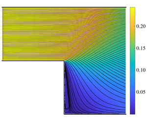
The free-molecular flow field in (a,b) density-driven ( $\unicode[STIX]{x1D70C}_{out}=0.1,T_{out}=1$) and (c,d) temperature-driven (
 $T_{out}=0.1,\unicode[STIX]{x1D70C}_{out}=1$) flow set-ups: (a,c) and (b,d) show results for channels with diffuse and specular walls, respectively. The contours and colourmaps show the flow streamlines and gas speeds, respectively.

5.1 Free-molecular regime
Focusing on free-molecular conditions, figure 5 first validates the ballistic analytical solution through comparison with collisionless DSMC results. The figure shows  $x$-variations of the density and
 $x$-velocity fields at a constant value of
 $y=0.002$, slightly above the step level
 $y=0$. The results are presented for both diffuse- and specular-reflecting channels. Density- and temperature-driven flow set-ups (with
 $\unicode[STIX]{x1D70C}_{out}=0.1$ and
 $T_{out}=0.1$, respectively) are shown in figures 5(a,b) and 5(c,d), respectively. The agreement between collision-free DSMC and analytical results is very good in all cases, supporting the accurateness of both schemes. Any small discrepancies may be attributed to the statistical scattering inherent in DSMC output, which is particularly visible in the specular wall set-up data. Based on the agreement in figure 5, as well as in all other parameter combinations studied, further results in this section are based on the analytical solution only, which requires only minor computational effort to carry out. The breakdown of the free-molecular regime with decreasing
 $Kn$ is discussed in § 5.2, where the effect of molecular collisions is introduced.
Inspecting the results in figure 5, the occurrence of a ‘jump’ in most of the hydrodynamic field values at the step section  $x=0$ is remarkable. This agrees with previous DSMC investigations (Agrawal et al. Reference Agrawal, Djenidi and Antonia2005; Xue et al. Reference Xue, Xu, Wei and Wu2005), reporting on a similar system trend at high Knudsen numbers, and may be rationalized based on the free-molecular flow analysis in § 3. To this end, it is recalled that particles reflected from the step wall cannot arrive directly at the upstream
 $x<0$ part of the channel. Specifically, in a diffuse-reflecting channel, passage to the
 $x<0$ part may occur only after an additional particle collision takes place with the downstream
 $l_{d}$ wall, or the
 $x>0$ part of the upper
 $l$ boundary. For specular-reflecting surfaces, passage of step-emitted particles to the upstream part of the channel is precluded at any stage. Common to both diffuse and specular configurations, it is this ‘invisibility’ of the step to the
 $-l_{u}\leqslant x<0$ end of the channel that results in sharp variations of the flow field at
 $x=0$. Following similar reasoning, these gradients are expected to reduce, as observed in Agrawal et al. (Reference Agrawal, Djenidi and Antonia2005) and Xue et al. (Reference Xue, Xu, Wei and Wu2005), with a decrease in the Knudsen number, since molecular collisions result in indirect transfer of momentum from the step wall to the upstream channel section.
While previous works have focused on channels with diffuse-reflecting boundaries only, the current results exhibit significant differences between these and the counterpart specular-reflecting configurations. In line with the specular wall analysis in § 3.2, the hydrodynamic fields in this case retain the constant values predicted by (3.19) for  $x<0$, whereas
 $x$- and
 $y$-variations are viewed for diffuse-reflecting channels. Notably, the density field retains its same constant value also for
 $x>0$ in the temperature-driven specular case (see the blue line and circles in figure 5c). This value remains unchanged also with
 $y$, which makes the temperature-driven flow in a specular-reflecting channel incompressible, regardless of the imposed temperature drop. As shown later on (see figure 9), this result is valid only in the free-molecular regime, whereas particle collisions, even to a small extent, turn the flow compressible. For later reference it is also noted that the
 $x$-velocity amplitudes obtained in the density-driven case are higher than in the temperature-driven case, although generated by the same imposed pressure drop,
 $p_{out}=\unicode[STIX]{x1D70C}_{out}T_{out}=0.1$. In addition, the velocity amplitude is, in most cases, larger in the specular compared with the diffuse wall set-up at fixed outlet conditions.
An overview of the flow field (streamlines and velocity amplitudes) generated in the density- and temperature-driven cases is presented in figure 6, which also compares between diffuse (figures 6a and 6c) and specular (figures 6b and 6d) reflecting channels. Inspecting the streamline contours, the flow appears fully attached to the step in all cases, with markedly low flow speeds in the vicinity of the step. In line with the results in figure 5, the flow speed in the density-driven case is significantly (more than twice) larger in the density-driven compared with the temperature-driven case. The extent of the speed jump at  $x=0$ (equivalent to the sharp gradients observed in figure 5 in the density and
 $x$-velocity component at
 $x=0$) reduces with increasing distance
 $y$ from the step edge singularity.
Further insight into the above results may be obtained by inspecting the effects of problem parameters on the gas mass flow rate,
 $$\begin{eqnarray}{\dot{m}}=\int _{0}^{1}\unicode[STIX]{x1D70C}(x<0,y)u_{x}(x<0,y)\,\text{d}y=\int _{-h_{s}}^{1}\unicode[STIX]{x1D70C}(x>0,y)u_{x}(x>0,y)\,\text{d}y,\end{eqnarray}$$
passing through the channel. Mass conservation considerations impose that  ${\dot{m}}$ is constant along the channel, and it is therefore sufficient to calculate its value at a single
 $x$-location. In the specular-reflecting case, substituting equation (3.19) into (5.1) and integrating, we find
 $$\begin{eqnarray}{\dot{m}}_{specular}=\frac{1}{2\sqrt{\unicode[STIX]{x03C0}}}(1-\unicode[STIX]{x1D70C}_{out}\sqrt{T_{out}}),\end{eqnarray}$$
indicating that the flow rate vanishes where  $\unicode[STIX]{x1D70C}_{out}\sqrt{T_{out}}=1$. Backward (with
 $u_{x}>0$) and forward (
 $u_{x}<0$) facing step flows occur for
 $\unicode[STIX]{x1D70C}_{out}\sqrt{T_{out}}<1$ and
 $\unicode[STIX]{x1D70C}_{out}\sqrt{T_{out}}>1$, respectively. The result in (5.2) is independent of the channel dimensions, and, in particular, of the step size, and is identical to the mass flow rate obtained through an infinitely thin slit (Cercignani Reference Cercignani1975). The linear and square-root dependencies of
 ${\dot{m}}$ on
 $\unicode[STIX]{x1D70C}_{out}$ and
 $T_{out}$, respectively, reflect the larger
 $x$-velocities obtained in the former case, as presented in figure 5 (cf. the dashed lines and circles in figures 5b and 5d).
While the channel geometry has no effect on the value of  ${\dot{m}}$ in the specular-reflecting set-up, it does alter the result for diffuse scattering walls. Different from the specular case, a particle entering the channel from the inlet reservoir may not leave it from the outlet when diffuse conditions are imposed. This results in reductions in both the flow speed, as reflected by the results in figures 5 and 6, and the overall mass flow rate, demonstrating the diminished ‘permeability’ of a diffuse channel to free-molecular gas transfer. Previous works have considered the effects of channel size and boundary conditions on free-molecular gas transfer in straight (non-stepped) channels, based on Clausing’s integral equation (Clausing Reference Clausing1932) and follow-up approximations (e.g. Berman Reference Berman1965; Helmer Reference Helmer1967). The particular impact of channel step on the free-molecular flow rate is discussed below.
Effects of the (a) outlet density  $\unicode[STIX]{x1D70C}_{out}$, (b) outlet temperature
 $T_{out}$ and (c) step height
 $h_{s}$, on the mass flow rate
 ${\dot{m}}$ in the free-molecular regime. Solid and dashed curves show results for channels with diffuse and specular walls, respectively. In (a,b),
 $h_{s}=1$, with
 $T_{out}=1$ in (a), and
 $\unicode[STIX]{x1D70C}_{out}=1$ in (b). In (c), the
 $\unicode[STIX]{x1D70C}_{out}=0.1$ and
 $T_{out}=0.1$ notations pertain to density-driven (with
 $T_{out}=1$) and temperature-driven (with
 $\unicode[STIX]{x1D70C}_{out}=1$) flow set-ups, respectively.

Figure 7 shows the effects of the outlet conditions  $\unicode[STIX]{x1D70C}_{out}$ and
 $T_{out}$, as well as the step size
 $h_{s}$, on the value of
 ${\dot{m}}$ in the collisionless-flow regime, for both diffuse- and specular-reflecting channels. The dashed curves illustrate expression (5.2) for
 ${\dot{m}}_{specular}$, showing the linear and square-root dependencies on
 $\unicode[STIX]{x1D70C}_{out}$ and
 $T_{out}$ in figures 7(a) and 7(b), respectively, and the independence on
 $h_{s}$ in figure 7(c). Inspecting the effect of diffuse wall conditions on
 ${\dot{m}}$, the comparison between the dashed and solid lines illustrates the reduction in the mass flow rate compared with the specular wall set-up. Thus, while
 ${\dot{m}}=0$ in both configurations for
 $\unicode[STIX]{x1D70C}_{out}=T_{out}=1$, the mass flow rate in the diffuse case is consistently lower by
 ${\dot{m}}_{diffuse}/{\dot{m}}_{specular}\approx 0.58$ in figures 7(a) and 7(b). The specific effect of the step size is shown in figure 7(c), where
 $h_{s}$ is varied for the density-driven (
 $\unicode[STIX]{x1D70C}_{out}=0.1,T_{out}=1$; black lines) and temperature-driven (
 $\unicode[STIX]{x1D70C}_{out}=1,T_{out}=0.1$; blue curves) flow set-ups. Different from the specular wall configuration,
 ${\dot{m}}$ is monotonically increasing with
 $h_{s}$ in the diffuse case, starting from its straight channel value at
 $h_{s}=0$, and reaching a plateau for
 $h_{s}\gtrsim 1$. Notably, although the step is obscured from the inlet section (as there are no particles emitted from the step and directly reaching the inlet; see § 3.1), it does affect the axial flow velocity and flow rate through the back reflection of particles arriving from the outlet, and the impact on the upper (
 $l$) and downstream (
 $l_{d}$) wall density fluxes,
 $\unicode[STIX]{x1D70C}_{l}(x)$ and
 $\unicode[STIX]{x1D70C}_{d}(x)$. For the choices of parameters made in figure 7(c), this leads to an increase in
 ${\dot{m}}_{diffuse}$ of more than 15 % between its non-stepped (
 $h_{s}=0$) and stepped (
 $h_{s}\gtrsim 1$) values. The highest value of
 ${\dot{m}}_{diffuse}$ is nevertheless smaller than its counterpart
 ${\dot{m}}_{specular}$ value, yielding the above-mentioned common
 ${\dot{m}}_{diffuse}/{\dot{m}}_{specular}\approx 0.58$ ratio in the cases presented.
Having studied the gas behaviour at large density and temperature drops between the inlet and outlet reservoirs, it appears of interest to examine the collisionless-flow regime in cases where smaller thermodynamic non-uniformities are imposed. As smaller thermodynamic drops result in lower flow velocities, the DSMC scheme becomes increasingly inefficient for  $\unicode[STIX]{x1D70C}_{out},T_{out}\rightarrow 1$ due to a significant decrease in the simulation signal to noise ratio. It is in this limit where the analytic solution becomes of particular value to study the free-molecular flow field, as described below.
Effects of the step size ((a,b)  $h_{s}=1$; (c,d)
 $h_{s}=3$) and outlet temperature ((a,c)
 $T_{out}=0.4$; (b,d)
 $T_{out}=0.8$) on the flow streamlines (curves) and gas speed (colourmaps) in the vicinity of the step wall (zone III) at free-molecular conditions. In all cases,
 $\unicode[STIX]{x1D70C}_{out}=1$, and the channel walls are diffusely reflecting. The dashed curves depict streamlines originating and ending at the
 $(0,0)$ and
 $(0,-h_{s})$ edges of the step surface, respectively.

Based on previous DSMC investigations (Xue et al. Reference Xue, Xu, Wei and Wu2005; Darbandi & Roohi Reference Darbandi and Roohi2011; Mahdavi et al. Reference Mahdavi, Le, Roohi and White2014; Mahdavi & Roohi Reference Mahdavi and Roohi2015; Gavasane et al. Reference Gavasane, Agrawal and Bhandarkar2018), it is expected that no flow detachment (in the form of step separation and recirculation) occurs at free-molecular conditions. This is supported by the results in figure 6, showing fully attached streamline profiles at the step in set-ups with high density and temperature drops. Yet, qualitatively different results are obtained at lower imposed drops, as illustrated in figure 8. The figure presents the effects of increasing  $T_{out}$ and the step size
 $h_{s}$ on the velocity field in the downstream
 $x\in [0,1],y\in [-h_{s},0]$ part of the channel, for
 $\unicode[STIX]{x1D70C}_{out}=1$. Each panel of the figure shows the flow streamlines (contours) and gas speed (colourmaps) at a given combination of
 $T_{out}$ and
 $h_{s}$. The results are based on the analytic solution, as the exceedingly low flow velocities (
 $|\boldsymbol{u}|\ll 0.01$) encountered in the vicinity of the step for these parameter combinations prohibit efficient application of the DSMC scheme (see the above discussion).
In a qualitative difference from the flow pattern in figure 6, the results in figure 8 indicate a zone in the vicinity of the step surface where the flow streamlines originate and end at the step  $(0,0)$ and
 $(0,-h_{s})$ edge points, respectively. Marking these streamlines by dashed curves, the extent of this zone increases with increasing
 $T_{out}\rightarrow 1$ and
 $h_{s}$, occupying nearly half of the downstream
 $l_{d}$ wall for the
 $T_{out}=0.8$ and
 $h_{s}=3$ combination in figure 8(d). This is accompanied by an overall decrease in the flow velocity amplitude, as depicted by the speed colourmaps. Along each of the dashed streamlines the gas translates from the upper
 $(0,0)$ to the lower
 $(0,-h_{s})$ stagnation points. Notably, this ‘detached’ zone is quantitatively different from the recirculation-flow pattern common at lower Knudsen numbers, where closed contour streamlines are formed (see, e.g. figures 10d–f). The present type of flow detachment may nevertheless be of fundamental and practical significance, as the gas located in the dashed streamline zone is separated from the bulk fluid by not transporting to the channel outlet section. With decreasing
 $T_{out}$ and
 $h_{s}$, higher gas velocities occur at the step wall, and the separated zone becomes thinner, as presented in figure 8(a). A similar behaviour, not presented here, was also obtained in the density-driven flow (
 $\unicode[STIX]{x1D70C}_{out}\rightarrow 1,T_{out}=1$) and specular-reflecting channel set-ups. Since higher flow velocities are obtained in these configurations (see figures 5b and 6a,b), relatively larger
 $\unicode[STIX]{x1D70C}_{out}\rightarrow 1$ values are required to observe detached gas layers of a similar size to those shown in figure 8.
5.2 Effect of molecular collisions
Breakdown of the free-molecular regime with decreasing Knudsen number:  $x$-variations at
 $y=0.01$ of the (a,c) density and (b,d)
 $x$-velocity fields for (a,b)
 $\unicode[STIX]{x1D70C}_{out}=0.1,T_{out}=1$ and diffuse-reflecting boundaries; (c,d)
 $\unicode[STIX]{x1D70C}_{out}=1,T_{out}=0.1$ and specular-reflecting boundaries. The solid line shows the free-molecular solution and the symbols mark DSMC data at the indicated values of
 $Kn$.

Having examined the collisionless regime in detail, we turn to discuss the backward step flow problem at relatively high, yet finite, Knudsen numbers. This is important to assess the range of validity of the free-molecular description at high  $Kn$, and to gain insight into the qualitative effect of non-frequent molecular collisions on the gas flow field.
To start, figure 9 examines the breakdown of the free-molecular regime with decreasing Knudsen number. Applying DSMC calculations, the figure shows  $x$-variations of the density and
 $x$-velocity component at a constant
 $y=0.01$, comparing the free-molecular (solid line) and finite-
 $Kn$ (symbols) distributions. Figures 9(a) and 9(b) present a density-driven flow set-up (
 $\unicode[STIX]{x1D70C}_{out}=0.1,T_{out}=1$) with diffuse-reflecting boundaries, whereas figures 9(c) and 9(d) show a temperature-driven configuration (
 $\unicode[STIX]{x1D70C}_{out}=1,T_{out}=0.1$) with specular-reflecting walls. For easy reference, the outlet reservoir conditions replicate those considered in figures 5 and 6.
Focusing on the density-driven set-up in figures 9(a) and 9(b), it is observed that the collisionless description remains valid till  $Kn\approx 1$, where molecular collisions result in a slight smoothing of the sharp jump obtained at
 $x=0$. The free-molecular field turns invalid for
 $Kn\lesssim 1$, where the effect of molecular collisions becomes more significant and results in large discrepancies from the collisionless result, as shown by the triangle-marked
 $Kn=0.1$ curve. While a qualitatively similar breakdown is observed in the temperature-driven flow set-up in figures 9(c) and 9(d), it is remarkable that observable differences (up to
 ${\approx}4\,\%$) are found even at
 $Kn=100$. It is therefore noted that the breakdown of the collisionless regime occurs at much higher Knudsen numbers in the set-up where lower flow speeds occur (cf. figures 6a and 6d). Here, even a seemingly slight impact of collisions results in a visible departure from the incompressible free-molecular state.
Effects of the Knudsen number ((a,d)  $Kn=5$; (b,e)
 $Kn=1$; (c,f)
 $Kn=0.1$) and outlet reservoir conditions ((a–c)
 $\unicode[STIX]{x1D70C}_{out}=0.1,T_{out}=1$ and diffuse-reflecting walls; (d–f)
 $\unicode[STIX]{x1D70C}_{out}=1,T_{out}=0.1$ and specular-reflecting walls) on the flow streamlines (curves) and gas speed (colourmaps).

Further insight into the breakdown of the collisionless regime is gained by inspecting the effect of decreasing  $Kn$ on the overall gas flow speed and streamlines. This is carried out in figure 10, which presents results for the diffuse-reflecting (figures 10a–c) and specular-emitting (figures 10d–f) configurations considered in figure 9. Starting with the former, it is observed that the flow field remains nearly unchanged between the
 $Kn=5$ and
 $Kn=1$ set-ups in figures 10(a) and 10(b), which are essentially identical with the collisionless-flow map in figure 6(a). This is in agreement with the results in figures 9(a) and 9(b), showing that the collisionless description remains effective up to
 $Kn\approx 1$ in this case. At
 $Kn=0.1$, however, the flow map in figure 10(c) indicates an increase in the gas speed, accompanied by some irregularities in the flow streamlines in the vicinity of the step. At slightly lower Knudsen numbers, these irregularities form into a distinct flow recirculation zone near the step. It is, therefore, within the transition between the attached and detached flow profiles, where increasing flow speeds occur in the bulk, and recirculating gas velocities first appear at the step, that the free-molecular description breaks down.
A similar observation, yet at considerably larger Knudsen numbers, can be made in the specular-reflecting set-up presented in figure 10(d–f). Here, according to figures 9(c) and 9(d), the breakdown of the free-molecular regime takes place at a much higher  $Kn\approx 100$. Reducing
 $Kn$ further, the results in figure 10(d) show that step detachment occurs already at
 $Kn=5$, and intensifies considerably (in terms of both velocity amplitude and recirculation zone size) with decreasing
 $Kn$. Characterized by lower speeds compared with the counterpart density-driven set-up, the temperature-driven flow is found to be more susceptible to detachment from the step at relatively higher levels of rarefaction.
In detecting flow separation in previous continuum investigations, an inspection of the wall shear stress variations along the downstream  $l_{d}$ surface has been undertaken, with a change in its sign identifying the flow reattachment point. Notably, this does not provide an appropriate criterion in the present problem, where large Knudsen number flows over diffuse- and specular-reflecting walls are considered. First, our results demonstrate that flow separation occurs also in specular-reflecting channels (see figure 10d–f), where the wall shear stress identically vanishes, with no change in sign permitted. Additionally, as illustrated by figure 8, the pattern of flow detachment at free-molecular conditions is composed of streamlines connecting the step edge points, not coinciding with any point along the downstream surface. Thus, rather than tracing the value of the wall skin friction, we suggest observing the quantitative pattern of the flow velocity field as a direct measure for the occurrence of flow separation. Specifically, flow detachment is determined in cases where coherent reverse flow is observed in the vicinity of the step, composing streamlines that do not commence or terminate at the inlet or outlet sections, and combining simultaneous negative and positive
 $x$- and
 $y$-velocity components, respectively. This direct criterion, which appears more appropriate in the current context, reveals the inefficiency of using the wall shear stress measure for detecting flow separation, and further demonstrates the significance of our results.
As the discussion in this section relies on DSMC calculations only, more rigorous analysis is desirable to clarify the effect of molecular collisions on the formation of step flow detachment. A starting point for such a calculation may be an inverse- $Kn$ power series representation of the solution to the Boltzmann equation, where the present collisionless description serves as a leading-order approximation. Obtaining higher-order correction terms may then assist in shedding light on the effects of particle interactions on step separation and reattachment phenomena. It may also be useful in extending the results in figure 8, for the free-molecular stagnation point detachment, to cases where molecular collisions occur. These topics will be addressed in a future work.
6 Conclusion
We studied the two-dimensional steady channel flow of a rarefied gas over a backward facing step in the limit of large Knudsen numbers. The free-molecular problem was solved analytically for both diffuse- and specular-reflecting channels, and the solutions were validated through comparison with collision-free DSMC calculations. Prescribing the density and temperature differences between the inlet and outlet external conditions, the results for density- and temperature-drop-driven flows were analysed, revealing higher flow velocities and mass flow rates in the former. While the flow rate was unaffected by the step geometry in the specular case, it was found to increase with the step size in the diffuse-reflecting set-up. At conditions where small flow velocities occur, free-molecular flow detachment was observed in the form of streamlines connecting the step edge stagnation points. Considering the problem at finite Knudsen numbers, the collisionless-flow regime was shown to break down at higher Knudsen numbers for lower gas speeds, followed by the occurrence of step separation and recirculation flows.
Reviewing existing studies on rarefied gas flows over micro-steps (Beskok Reference Beskok2001; Baysal et al. Reference Baysal, Erbas and Koklu2004; Xue et al. Reference Xue, Xu, Wei and Wu2005; Hsieh et al. Reference Hsieh, Hong and Pan2010; Bao & Lin Reference Bao and Lin2011; Darbandi & Roohi Reference Darbandi and Roohi2011; Mahdavi et al. Reference Mahdavi, Le, Roohi and White2014; Mahdavi & Roohi Reference Mahdavi and Roohi2015; Gavasane et al. Reference Gavasane, Agrawal and Bhandarkar2018), the current work presents several new findings that are of fundamental and practical significance. In contrast to the common view, it is first demonstrated that step detachment may occur at free-molecular conditions, identified by a unique velocity profile. It is then shown that ‘conventional’ flow detachment, in the form of a recirculating flow reattaching along the downstream channel wall, may occur at high (yet finite) Knudsen conditions, which are not captured by the collisionless description. Different from existing works, the present contribution considers the impact of replacing the (previously studied) diffuse with specular wall conditions on the flow characteristics. Unlike in a diffuse-reflecting channel, the step is completely obscured from the upstream part of a specular channel, resulting in uniform flow along its upstream section (see figures 6b and 6d). This, in turn, results in mass flow rates that are larger in the specular-reflecting configuration, and are unaffected by the step geometry. Comparing the set-ups of temperature- and density-drop-driven flows, our work rationalizes the higher flow rates in the latter. Making use of expression (5.2) for  ${\dot{m}}_{specular}$, the respective linear and square-root dependencies of the specular channel flow rate on the density and temperature drops are attributed to the lower gas velocities obtained in the temperature-driven case, making it more susceptible to flow separation. The free-molecular analysis is also useful for rationalizing the previously reported steep flow-field gradients obtained at the step section at high Knudsen numbers (Agrawal et al. Reference Agrawal, Djenidi and Antonia2005; Xue et al. Reference Xue, Xu, Wei and Wu2005), and explains their decay with decreasing
 $Kn$ (see figure 5 and its discussion).
The present work may be followed in several directions. A relatively straightforward extension would be the analysis of the effect of thermal boundary conditions on the gas flow field in the ballistic regime. Relevant in a diffuse wall set-up, this may be carried out by either varying the wall temperatures, as carried out in Mahdavi et al. (Reference Mahdavi, Le, Roohi and White2014) and Mahdavi & Roohi (Reference Mahdavi and Roohi2015) using the DSMC method, or by changing the type of conditions from isothermal- to heat-flux-prescribed walls. In a different context, the free-molecular description may be also useful in analysing the impact of wall geometry on the Knudsen diffusivity (namely, the effective permeability) of a gas in a porous medium, where the pore size is small compared with the molecular mean free path (Celestini & Mortessagne Reference Celestini and Mortessagne2008). Here, the effect of pore boundary conditions should be significant, as demonstrated in previous studies (Santra & Sapoval Reference Santra and Sapoval1998; Arya, Chang & Maginn Reference Arya, Chang and Maginn2003; Krekelberg et al. Reference Krekelberg, Shen, Errington and Truskett2011).
A more elaborate extension of the present contribution would be a direct analysis of the effect of molecular collisions on the system state based on the Boltzmann kinetic equation. Inspecting the results in figure 10, it appears that step flow separation and reattachment may occur at relatively large Knudsen numbers. Using the collisionless-flow description as a leading-order approximation, it may therefore be possible to expand the solution for the Boltzmann equation in inverse powers of the Knudsen number, and obtain higher-order corrections that may shed light on the microscopic description of gas-flow detachment. This, as well as the above, consist of topics for future investigations.
Declaration of interests
The authors report no conflict of interest.


 Open access

