Introduction
In recent years, metallic laminated composites have attracted more and more attention due to their superior mechanical properties such as good synergy of strength/ductility and outstanding fatigue properties [Reference Seok, Lee, Lee, Ramamurty, Nambu, Koseki and Jang1, Reference Kümmel, Hausöl, Höppel and Göken2, Reference Liu, Zhang and Zhang3, Reference Liu, Huang, Geng, Kaveendran, Wang, Song and Cui4, Reference Huang, Wang, Ma, Yin, Höppel, Göken, Wu, Gao and Zhu5]. The main reason is that the macroscopic layer interfaces with mechanical contrast could achieve effective strain/stress transfer during coordinated deformation [Reference Huang, Xu, Fan, Maawad, Gan, Geng, Lin, Tang, Wu, Du, Li, Miao, Zhang, Yang, Xia, Cao, Kang, Wang, Xiao and Xie6, Reference Bian, Yuan, Wu and Zhu7, Reference Radchenko, Anwarali, Tippabhotla and Budiman8, Reference Anwar Ali, Radchenko, Li and Budiman9] and resist the fatigue crack propagation through local delamination and crack deflection/bifurcation [Reference Kümmel, Hausöl, Höppel and Göken2, Reference Liu, Zhang and Zhang3]. Thus, many researchers focus on maximizing the interface effect on the mechanical behavior, especially fatigue behavior of metallic laminated composites by tuning structural parameters such as interface bonding strength and layer thickness (h) [Reference Ma, Huang, Moering, Ruppert, Höppel, Göken, Narayan and Zhu10, Reference Nambu, Michiuchi, Inoue and Koseki11].
With further decreasing h, the nanolayered composites (NLCs) has found a wide range of applications for micro-electro-mechanical system (MEMS) components, advanced structural materials, and high-performance coatings due to their ultrahigh hardness and strength contributed by the strong constraint of high-density interfaces on dislocation activities [Reference Schweitz, Chevallier, Bottiger, Matz and Schell12, Reference Anderson, Foecke and Hazzledine13, Reference Misra, Hirth and Hoagland14]. Misra et al. [Reference Misra, Hirth and Hoagland14] have summarized three kinds of strengthening mechanisms with varying h: (i) dislocation pileup against the interface at sub-micrometer length scale; (ii) glide of single dislocation confined to individual layers at length scales of a few to a few tens of nanometers; and (iii) a single dislocation cutting through the interface at a length scale of a few nanometers. Considering that typical dislocation structures such as dislocation cells/walls cannot form at such ultrafine scale and the service demand for mechanical reliability of multilayered components and parts is increasing, the fatigue performance and failure mechanisms of NLCs are of scientific and industrial interest. Some studies of metal thin films have revealed a size effect on the fatigue behavior with varying film thickness. Zhang et al. [Reference Zhang, Volkert, Schwaiger, Wellner, Arzt and Kraft15, Reference Zhang, Volkert, Schwaiger, Arzt and Kraft16] found the transition of the fatigue damage mode from typical fatigue extrusions/intrusions to the intergranular cracks at grain boundaries (GBs) with decreasing film thickness from micrometer to submicron in thin Cu films. Compared with metal thin films, there is a high density of heterogeneous interfaces with modulus/lattice mismatch in the NLCs [Reference Koehler17, Reference Hoagland, Mitchell, Hirth and Kung18]. Li et al. [Reference Li and Zhang19] investigated the effect of constituent layer interface on the plasticity and fracture mechanisms of Cu/Au and Cu/Cr NLCs. It is found that the plasticity of Cu/Au NLCs is better than that of the Cu/Cr ones because the slip system between the Cu and Au layers was continuous across the Cu/Au transparent interface compared with the Cu/Cr opaque interface. Thus, not only the length scale such as layer thickness and grain size but also the interface type would have an impact on the fatigue behavior of metallic NLCs.
In this overview, we systematically summarize the worldwide researches about the fatigue performance of metallic NLCs in recent years. Then, we analyze and discuss the effect of length scale and interface type on the cyclic deformation behavior, cracking mode, and fatigue life of metallic NLCs. Finally, we present the prospect of future research about fatigue mechanisms of NLCs with combination of our recent research results, which could be instructive for fabricating NLCs with superior fatigue properties in the future.
Cyclic damage behavior
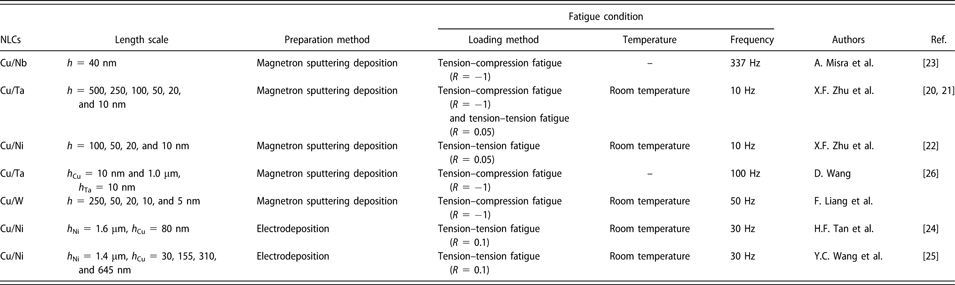
Table I presents some metallic NLCs with different material systems for the worldwide mechanical fatigue research and corresponding experiment parameters in recent years [Reference Zhu and Zhang20, Reference Zhu, Zhang, Tan, Liu and Zhu21, Reference Zhu and Zhang22, Reference Wang, Misra and Hoagland23, Reference Tan, Zhang, Luo, Zhu and Zhang24, Reference Wang, Liang, Tan, Zhang and Zhang25, Reference Wang, Gruber, Volkert and Kraft26]. It seems that all the materials focus on Cu/X (X = Ni, Ta, Nb, and W) system, which were prepared by magnetron deposition and electrodeposition, which are widely used in the MEMS, coatings, and structure materials field [Reference Yang, Imasogie, Allameh, Boyce, Lian, Lou and Soboyejo27, Reference Hou, Hamilton, Horn and Jin28]. Considering the fatigue failure of NLCs is defined as the appearance of fatigue crack [Reference Zhu and Zhang22, Reference Wang, Misra and Hoagland23, Reference Zheng, Luo, Wang and Zhang29], the cyclic damage behavior of NLCs is first discussed.
Material systems and experiment parameters of mechanical fatigue by some researchers [Reference Zhu and Zhang20, Reference Zhu, Zhang, Tan, Liu and Zhu21, Reference Zhu and Zhang22, Reference Wang, Misra and Hoagland23, Reference Tan, Zhang, Luo, Zhu and Zhang24, Reference Wang, Liang, Tan, Zhang and Zhang25, Reference Wang, Gruber, Volkert and Kraft26].

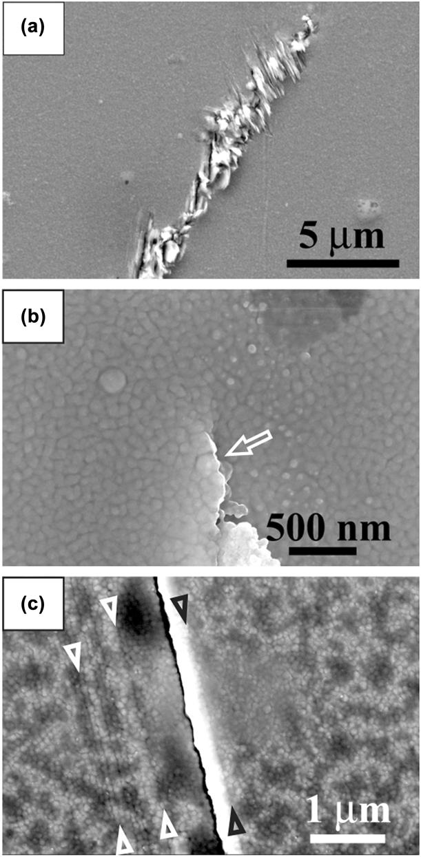
With decreasing length scale from submicron to nanometer, the typical fatigue extrusion/intrusion similar to that of bulk materials would transform into interface-mediated damage [Reference Zhang, Volkert, Schwaiger, Wellner, Arzt and Kraft15, Reference Zhang, Volkert, Schwaiger, Arzt and Kraft16]. Our recent research on fatigue properties of Cu/Ta NLCs seems to have proved such conclusion [Reference Zhu and Zhang20]. The SEM observation of the sample surface of the h = 500 nm Cu/Ta NLCs shows that surface slip damage was adjacent to the main fatigue crack after bending fatigue test for 6.5 × 10⁶ cycles, as shown in Fig. 1(a). For the h = 20 nm Cu/Ta NLCs, intergranular crack with macroscopic grain extrusion instead of dislocation slip damage was found, as shown in Fig. 1(b). The grain extrusion could be caused by the friction between crack surfaces during the tension–compression fatigue process, which is not the same as the typical fatigue extrusion induced by dislocation activity. We also found some fine line-like traces which were further identified as aligned grain boundaries (AGBs) in the localized deformation region for the h = 10 nm Cu/Ta NLCs after tension–tension fatigue for 1 × 10⁶ cycles, as shown in Fig. 1(c). The AGBs observed in the h = 10 nm Cu/Ta NLCs are believed to be related to grain rotation and GB sliding assisted by potential GB diffusion during the fatigue process [Reference Zhu, Li, Zhang and Zhu30, Reference Zhang, Zhu, Tan and Liu31, Reference Meyers, Mishra and Benson32].
SEM images of surface damage morphologies in the (a) h = 500 nm, (b) h = 20 nm, and (c) h = 10 nm Cu/Ta NLCs.

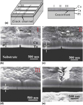
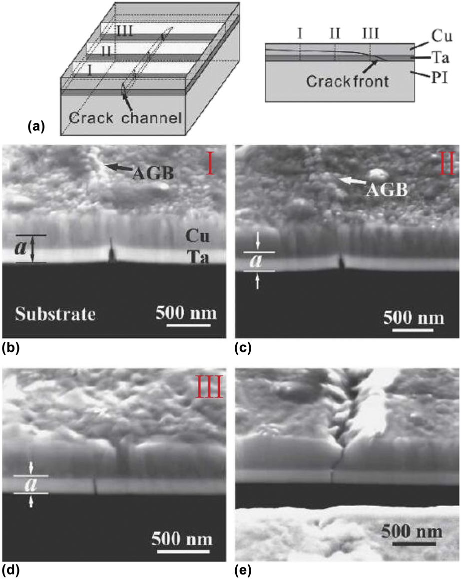
However, the AGB morphology is not limited to the NLCs with h ranging from a few nanometers to a few tens of nanometers where GB-mediated plasticity is preferred. In fact, we have ever found evident AGBs in the damage zone ahead of the crack tip in the 550-nm-thick Cu/250-nm-thick Ta bilayered films at Δσ = 370 MPa after 106 cycles [Reference Zhu, Zhang, Tan, Liu and Zhu21]. Figures 2(a)–2(e) indicates that the AGBs could not occur until the crack propagated through the Cu–Ta interface and intruded into the Cu layer instead of staying in the Ta layer. Concerning that typical dislocation walls/cells cannot form due to the constraint of GBs, the reason for the formation of AGBs could be the fact that the high plastic strain ahead of crack tip cannot merely be accommodated by dislocation emission. Thus, GB-mediated cyclic deformation is expected to occur.
(a) Schematic illustration of the damage zone ahead of a channel crack in the fatigue-damaged Cu/Ta bilayers, which is cross-sectioned at positions I, II, and III. Subsequent SEM cross-sectional views taken at (b) position I with the deformation zone related to AGBs, (c) position II with the deformation zone related to AGBs, (d) position III, where the channel crack only stays in the Ta layer, and (e) a through-thickness channel crack.
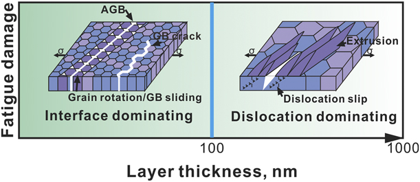
Obviously, there is a transition from the extrusion/intrusion morphology associated with dislocation slip activities to the GB-mediated damage mode such as AGBs and GB cracking with decreasing h, as depicted in Fig. 3. The cross-sectional TEM characterization indicates that the upmost W layers consist of nanoscale columnar grains with an average grain size of 39.5 nm. Regarding that the grain size of W is much less than the layer thickness, the dislocation activity might be strongly constrained by the boundaries of nanoscale columnar grains [Reference Chen, Liu, Sun, Yu, Song, Wang and Zhang33], and typical extrusions/intrusions might not form during the fatigue process.
Schematic illustration of cyclic damage behavior of NLCs as a function of layer thickness.

In general, the layer thickness and the grain size are the two length scales controlling the fatigue damage behavior of the NLCs, and the strong constraint of the smaller one on the dislocation activity would dominate the transition of the typical extrusion/intrusion mode to the interface-mediated damage behavior. In addition, the locally high plastic strain zone ahead of a crack tip could also magnify the effect of GB-mediated deformation through the formation of AGBs.
Fracture behavior along thickness direction (TD)
NLCs always exhibit poor ductility due to strongly suppressed dislocation activity with decreasing length scale, which gives rise to much more attention on the fracture mode, especially fatigue fracture mode of NLCs in recent years [Reference Li and Zhang19, Reference Zhang, Zhang, Liu, Zhang and Sun34, Reference Zhou, Zhang, Wei, Wang, Huang and Xu35, Reference Zhu, Li, Zhang, Tan and Liu36]. The layer interface with microstructure/mechanical contrast in the NLCs could effectively resist crack propagation during the fatigue process [Reference Tan, Zhang, Luo, Zhu and Zhang24, Reference He and Hutchinson37, Reference He, Evans and Hutchinson38]. Wang et al. [Reference Wang, Liang, Tan, Zhang and Zhang25] studied the effect of thickness ratio of constituent layers on the fatigue fracture mode of Cu/Ni NLCs fabricated by electrodeposition. It is found that the ultrafine Cu layer led to the formation of steps/fragments in the Cu/Ni multilayers by alternate variation of local delamination and crack deflection crossing the Cu/Ni layers, which could increase the crack growth path and dissipate more energy [Reference Parmigiani and Thouless39].
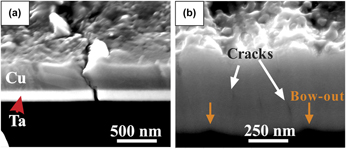
With decreasing the layer thickness to nanometer scale, the constraint effect of the interface on the crack propagation along TD would be more prominent. Our research on the fatigue cracking behavior of Cu/Ta and Cu/W NLCs showed an evident transition from ductile shear fracture for the Cu layers and normal fracture for the Ta or W layers to interface-dominated cracking behavior with decreasing h [Reference Zhu and Zhang20]. Figure 4(a) shows the cracking morphology of h = 500 nm Cu/Ta NLCs along TD at Δσ = 436 MPa after 106 cycles. The grain orientation in the deformation influence zone (DIZ) is quite close, and the width of DIZ is corresponding to that of the surface slip damage zone. The crack is believed to originate from the Ta/PI interface and propagated along the columnar GBs of Ta layers. When the crack approached the Cu/Ta interface, the intensive dislocation activity in the plastic zone near the crack tip led to the shear fracture of the Cu layers. The morphology of overall bow-out along TD instead of ductile shear under the surface deformation zone of AGBs were observed for the h = 10 nm Cu/Ta NLCs at Δσ = 781 MPa after 106 cycles, as shown in Fig. 4(b). Fatigue cracks were found to originate from the edge of the deformation zone of AGBs.
Cross-sectional observation of crack propagation behavior for (a) h = 500 nm Cu/Ta NLCs, (b) h = 10 nm Cu/Ta NLCs.

In addition to the effect of interface constraint on the fracture mode of NLCs, the GB morphology/distribution along TD also has a great impact on the fatigue cracking path. A multi-step morphology near the fracture was observed in the h = 20 nm Cu/W NLCs fatigued to 107 cycles through repeatedly bending fatigue method under constant deflection control, while fatigue cracks propagating straightly along TD were found in the h = 5 nm Cu/W NLCs. Since the Cu/W interface has large mechanical and thermal incompatibility across the interface and microvoids are likely to appear at the GBs, both of them are prone to cause fatigue cracking. Thus, the difference in the crack propagation behavior was attributed to various degrees of GB alignment of constituent layers along TD. The enhanced degree of Cu GBs alignment in adjacent Cu layers and the formation of integral columnar grains with decreasing h is due to the replication of island nucleation/growth during the fabrication process of NLCs. The stronger growth tendency of integral columnar grains with decreasing h greatly enhances the degree of Cu GBs alignment in adjacent Cu layers along TD. Thus, fatigue cracks could propagate through the columnar GBs in constituent layers of the h = 5 nm Cu/W NLCs. While for h = 20 nm Cu/W NLCs, cracks approaching the Cu/W interface have to advance along the interface for a relatively long distance and then further propagate along the GBs of adjacent layers due to interlacing GBs.
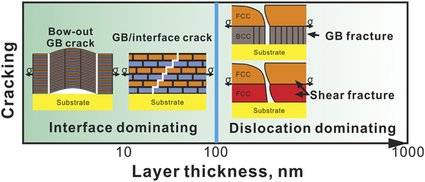
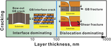
The above results reveal that there is a transition of fatigue cracking behavior from dislocation-dominated shear fracture/GB fracture to interface-dominated damage such as GB/interface/columnar GB crack and bow-out with decreasing h, as depicted in Fig. 5. The interface-dominated mechanism might be associated with grain rotation and GB/interface slip, but more detailed interface-dominated process requires further microstructure characterization and even in situ experimental work combining theoretical simulation. It is worth noting that the fracture mechanisms discussed above might only be applicable to the Cu-X (X = Ni, W, Ta, and Nb) NLCs with medium/high stacking fault energy (SFE) due to the dislocation-dominated deformation behavior. An extensive interaction between dislocations and twin boundaries should be considered when the cyclic deformation behavior and damage mechanisms of metallic NLCs with low SFE such as Ag/Fe [Reference Li, Chen, Xue, Wang and Zhang40] multilayers are analyzed. Besides, regarding that phase structure transformation has been detected in some fcc/bcc and fcc/hcp NLCs with decreasing h, such as Cu/Co [Reference Liu, Chen, Yu, Wang, Chen and Zhang41], Al/Ti [Reference Banerjee, Zhang, Dregia and Fraser42], Cu/Ru [Reference Zhou, Zhang, Wei, Wang, Huang and Xu35, Reference Zhou, Li, Wang, Huang, Lu and Xu43], and Cu/Ni/W [Reference Yan, Zhang, Zhu, Liu and Yan44] NLCs, the transition of lattice structure could have great impact on the fatigue properties of the NLCs. And the increasing interface coherency [Reference Bufford, Bi, Jia, Wang and Zhang45, Reference Lu, Kotoka, Ligda, Cao, Yarmolenko, Schuster and Wei46, Reference Mara, Bhattacharyya, Dickerson, Hoagland and Misra47] with decreasing h could lead to dislocation crossing the layer interface during the fatigue process, which might degrade fatigue properties of the NLCs. Such investigations on fatigue performance of metallic NLCs with low SFE and potential effect of transition of the phase and interface structures still need to be conducted.
Schematic illustration of cracking behavior of NLCs as a function of layer thickness.

Fatigue life
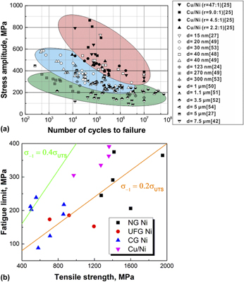
Figure 6(a) shows the stress amplitude–fatigue life diagram of the ultrafine-scale Cu/Ni–laminated composites [Reference Tan, Zhang, Luo, Zhu and Zhang24, Reference Wang, Liang, Tan, Zhang and Zhang25] and pure Ni with various grain sizes [Reference Yang, Imasogie, Allameh, Boyce, Lian, Lou and Soboyejo27, Reference Baek, Lee, Guagliano and Vergani48, Reference Cavaliere49, Reference Aktaa, Reszat, Walter, Bade and Hemker50, Reference Son, Kim, Lim and Kwon51, Reference Allameh, Lou, Kavishe, Buchheit and Soboyejo52, Reference Hanlon, Tabachnikova and Suresh53, Reference Boyce, Michael and Kotula54]. It is evident that the fatigue strength at the same number of cycles to failure increases with decreasing grain size from micrometer to nanometer for the pure Ni, which follows the general trend that fatigue strength has positive correlation with ultimate tensile strength (UTS). Figure 6(b) shows relationship between the fatigue limit and the tensile strength of ultrafine-scale Cu/Ni–laminated composites and pure Ni consisted of nanograins (NG), ultrafine grains (UFG), and coarse grains (CG), respectively. Compared with pure UFG Ni, the ultrafine-scale Cu/Ni–laminated composites consisted of UFG Ni grains and ultrathin Cu layers exhibit a higher fatigue limit (391 MPa) under the high UTS (1361.80 MPa). The introduction of ultrathin Cu layers could effectively resist the crack propagation and enhance high-cycle fatigue properties without losing tensile strength, indicating that the laminate structure is likely to acquire an optimal synergy between tensile strength and the fatigue strength through the constraint effect of layer interfaces.
(a) Applied stress amplitude versus number of cycles to failure curve and (b) fatigue limit versus tensile strength for the Cu/Ni laminated composites and pure Ni with different grain sizes including NG, UFG, and CG.

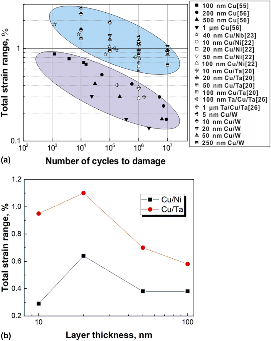
Figure 7(a) presents a summary of the relationship between the applied total strain range and the number of cycles to failure for Cu/X (X = Ni, Ta, Nb, and W) NLCs and Cu thin films [Reference Zhu and Zhang22, Reference Wang, Misra and Hoagland23, Reference Sun, Wang, Zhang, Liu, Zhang, Ding, Zhang and Sun55, Reference Wang, Volkert and Kraft56]. For the Cu/Ta and Cu/Ni NLCs, tension–tension fatigue loading was firstly conducted for 1 × 10⁶ cycles at a certain strain range. If no fatigue damage at the specimen surface was observed, another 1 × 10⁶ cycle fatigue loading was conducted at a larger strain range than that before until the fatigue damage was observed [Reference Zhu and Zhang22]. For the Cu/W and Cu/Nb multilayers, repeatedly bending fatigue tests were conducted, and critical strain ranges were determined by the minimum applied strain range leading to fatigue cracking [Reference Zheng, Luo, Wang and Zhang29] and appearance of frequency shift [Reference Wang, Misra and Hoagland23], respectively. Here, the applied total strain range (Δε) is defined as the specific strain that corresponds to the appearance of fatigue crack [Reference Zhu and Zhang22, Reference Zheng, Luo, Wang and Zhang29, Reference Sim, Hwangbo, Kim, Lee and Vlassak57]. The relation between the applied strain range and the number of cycles to failure (fatigue life, N f) could accord with the Coffin–Manson relation as follows [the fitting results are not put in Fig. 7(a)]:
 $${{\Delta \varepsilon } / 2} = {\varepsilon '_{\rm{f}}}{\left( {2{N_{\rm{f}}}} \right)^c}\quad .$$
where  ${\varepsilon '_{\rm{f}}}$ and c are the fatigue ductility coefficient and fatigue ductility exponent, respectively. It is evident that for a given fatigue life, the applied strain ranges increases significantly with decreasing layer of thickness for both the NLCs, which is in accordance with the positive correlation between strength and fatigue strength. Also the applied strain ranges of the h = 5–250 nm Cu/W, Cu/Ni, Cu/Nb, and Cu/Ta NLCs [a circled blue region in Fig. 7(a)] are all larger than those of the 0.1–1.0-μm-thick Cu films [a circled pink region in Fig. 7(a)] under given fatigue cycles, which indicates that the introduction of high-density heterogeneous interfaces could effectively enhance the fatigue properties through local interface-coordinated plastic deformation and strong retardation to the fatigue crack propagation, such as the resistance to a dislocation crossing the layer interface, the possible annihilation of vacancies produced by the dislocation interaction and trapping, and the deflection of a crack at the interface. In addition, the interface type also has a great influence on fatigue properties of the NLCs. As shown in Fig. 7(b), the total strain range of fcc Cu/bcc Ta NLCs is higher than that of fcc Cu/fcc Ni NLCs under the same layer thickness. The XRD scan results show the out-of-plane orientation for Cu〈111〉, Ta〈111〉, and Ni〈111〉 in the Cu/Ta and Cu/Ni NLCs with various layer thicknesses [Reference Zhu, Zhang, Tan, Liu and Zhu21, Reference Zhu and Zhang22]. Considering that the slip system between the Cu and Ni layers was continuous across the Cu/Ni interface, i.e., the transparent interface, while that between the Cu and the Ta layers was discontinuous. The effective resistance to dislocation transmission at Cu/Ta opaque interface might lead to the enhanced fatigue properties.
(a) Applied total strain range versus number of cycles to damage for the NLCs and Cu thin films with different layer thicknesses. (b) Applied total strain range versus layer thickness for the Cu/Ni and Cu/Ta NLCs.

Summary and outlook
The rapid development in the field of MEMS, high-performance coatings, and advanced engineering structure materials has motivated the scale of materials to be smaller and smaller. At the same time, the long-term fatigue reliability of NLCs is increasingly demanded. It is a great challenge to understand the relationship between microstructure/interface and fatigue damage/cracking behavior with decreasing the length scale for the NLCs. For fatigue damage, there is a transition of dislocation-dominant cyclic strain localization through the formation of fatigue extrusions/intrusions to interface-mediated damage such as AGBs and GB crack with decreasing h. For fatigue cracking behavior along TD of the NLCs, there is a transition of dislocation-dominant shear fracture to interface-coordinated deformation such as bow-out and GB/interface fracture with decreasing h. We also know that the introduction of high-density heterogeneous interface in NLCs could effectively coordinate local plastic deformation and resist crack propagation, which leads to the enhanced fatigue property compared with individual constituent layers and metal thin films. Although the size effect in the fatigue behavior of NLCs has been found, there are still much work about fabricating high strength/fatigue strength NLCs and deep understanding of microscopic mechanisms to be done in the future. Some issues are as follows.
(1) The direct observation and deep understanding of the process of interface-coordinated deformation and damage evolution, such as the formation of AGBs and overall bow-out, is still needed. Recently, Ali et al. [Reference Anwar Ali, Radchenko, Li and Budiman9] studied the fracture behavior of Cu/Nb NLCs through in situ beam bending experiments inside an SEM, which is very instructive to fatigue research of NLCs.
(2) There is very little research about the effect of interface type on the fatigue performance of NLCs. Radchenko et al. [Reference Radchenko, Anwarali, Tippabhotla and Budiman8] found that the Cu/Nb NLCs with higher interface shear strength could effectively resist the formation of shear bands. Although it has been shown that the fatigue strength of NLCs with opaque interface is better than that of NLCs with transparent interface, the systematic work about the interaction of dislocations with the heterogeneous layer interface, the role of the interface in the damage evolution and stability of the interface during the fatigue process is required.
(3) There has been some work about increasing fracture toughness and thermal stability of nanoscale thin films and NLCs by tuning cross-sectional GB [Reference Daniel, Meindlhumer, Baumegger, Zalesak, Sartory, Burghammer, Mitterer and Keckes58, Reference Mara and Beyerlein59, Reference Zheng, Carpenter, McCabe, Beyerlein and Mara60, Reference Mara, Tamayo, Sergueeva, Zhang, Misra and Mukherjee61, Reference Zheng, Beyerlein, Carpenter, Kang, Wang, Han and Mara62]. However, little direct experimental information exists on fatigue performance of these materials. In recent years, very striking work on the effect of bimetal interface structure on the mechanical behavior of Cu/Nb NLCs prepared by accumulated rolling bonding (ARB) and physical vapor deposition (PVD) was conducted by Beyerlein et al. [Reference Mara and Beyerlein59, Reference Zheng, Beyerlein, Carpenter, Kang, Wang, Han and Mara62]. They attributed the enhanced thermal stability of the ARB-fabricated Cu/Nb NLCs to the stability of Cu/Nb interfaces and a low density of unstable GBs. Thus, simultaneous high strength and thermal stability could be achieved through combination of stable bimetal interfaces and increased in-plane grain size of constituent layers. Recent work by Ali et al. [Reference Anwar Ali, Radchenko, Li and Budiman9] also indicated that the lower density of brittle GBs of ARB-fabricated Cu/Nb NLCs could avoid the appearance of sudden and catastrophic fracture during the bending process, compared with PVD samples. Thus, it would be interesting to know whether such ARB-fabricated bulk Cu/Nb NLCs with stable Cu/Nb interfaces and a low density of unstable and brittle GBs would exhibit good fatigue performance. Similarly, according to our previous work, the enhanced fatigue strength could be achieved through increasing the tortuosity degree of the fatigue crack path and corresponding resistance to crack propagation. All these imply an effective way for NLCs to obtain superior combination of tensile strength and fatigue strength through modulating the stability of constituent layer interface, the GB density, and the degree of GBs alignment. However, such exploration is just in the beginning.
Acknowledgments
This work was supported by the National Natural Science Foundation of China (NSFC, Grant Nos. 51571199 and 51601198). XML acknowledges the support from “Young Merit Scholars” of Institute of Metal Research, Chinese Academy of Sciences.