I. INTRODUCTION
The as-cast microstructure of Cr–Ni austenitic stainless steels varies greatly and typically consists of ferrite and austenite.Reference Lo, Shek and Lai1–Reference Kim, Moon, Kang and Lee5 A variety of ferrite morphologies were observed in the solidified microstructure of austenitic stainless steels due to complicated solidification and subsequent solid-state transformation behaviors.Reference Herlach6–Reference Edström, Ito and Thomas10 It is now recognized that ferrite morphology has a great effect on the hot cracking susceptibility, corrosion resistance, and low temperature fracture toughness of the class of steels.Reference Fukumoto, Okane, Umeda and Kurz11,Reference Baldissin and Battezzati12 Among all the ferrite morphologies, lathy ferrite is a commonly observed morphology in the as-cast microstructure of austenitic stainless steels, especially in the welds.Reference Brooks, Williams and Thompson13–Reference Lin, Yue, Yang and Huang17 Recently, we have revealed the formation details and the origin of the lathy ferrite using directional solidification and quenching in AISI 304 stainless steel.Reference Fu, Yang, Guo, Ma and Tong18,Reference Fu, Yang, Guo, Ma and Tong19 However, the reason why the entangled lathy ferrite grows in an irregular morphology during solidification is still not clear.
In steels, many crystallography relationships have been confirmed.Reference Headley and Brooks20–Reference Zhang and Kelly25 Morito et al.Reference Morito, Tanaka, Konishi, Furuhara and Maki21 examined the morphology and crystallography of lath martensite in Fe–C alloys containing various carbon contents from 0.0026 to 0.61%. It was found that the orientation relationship between austenite and martensite varies with carbon content and the orientation relationship is near Kurdjumov–SachsReference Kurdjumov and Sachs26 relationship and some laths seem to have nearly Nishiyama–WassermannReference Nishiyama27,Reference Wassermann28 relationship. For alloy steels,Reference Morito, Huang, Furuhara, Maki and Hansen22 it was reported that the crystallographic features are similar to those observed in low-carbon steels.Reference Morito, Tanaka, Konishi, Furuhara and Maki21 The morphology and crystallography of austenite precipitates in a duplex stainless steel were studied using TEM.Reference Qiu and Zhang23 It was shown that the austenite precipitates always hold a near Kurdjumov–Sachs orientation relationship with their ferrite matrix. Mangan et al.Reference Mangan, Kral and Spanos24 investigated the correlation between the crystallography and morphology of proeutectoid Widmanstätten cementite precipitates in Fe-1.34 wt% C-13.1 wt% Mn alloy. The orientation relationships between the proeutectoid Widmanstätten cementite precipitates and the surrounding austenite were determined to be or very close to either PitschReference Pitsch29 or Farooque–Edmonds orientation relationship. Zhang and KellyReference Zhang and Kelly25 examined the orientation relationships between Widmanstätten cementite and austenite in Fe–C–Mn alloy containing 0.55–2.41% silicon. They obtained a new orientation relationship between Widmanstätten cementite and austenite, which is related to the Farooque–Edmonds relationship by a 2.2° rotation about [100] direction of cementite.Reference Mangan, Kral and Spanos24,Reference Zhang and Kelly25
Based on the above analyses, it is clear that previous works mainly focus on the relationship between the morphology and crystallography during solid-state transformation. No works referring to the relationship between entangled lathy ferrite morphology and the crystallography during solidification have been performed. In this work, the crystallography between an entangled lathy ferrite and austenite during solidification was examined using transmission electron microscopy (TEM). The formation mechanism of the entangled lathy ferrite was proposed in terms of the crystallography between the lathy ferrite and austenite.
II. EXPERIMENTAL PROCEDURE
In this work, a commercial AISI 304 stainless steel was used. The alloy was melted to cast rods with a diameter of 8.0 mm and a length of 150 mm using a vacuum induction furnace under a controlled argon atmosphere. The nominal composition (wt%) of the alloy was 17.93 Cr, 8.76 Ni, 0.77 Mn, 0.56 Si, 0.048 C, 0.031 P, 0.013 S, and Fe the balance. As-machined rods of 7.0 mm diameter and 120 mm length were contained in an alumina tube. Directional solidification experiments were carried out under a controlled argon atmosphere. The temperature gradient in the liquid was about 20 K/mm, and the pulling rate was 50 μm/s. After heating to and stabilization at 1873 K, the sample was pulled down with the given velocity for steady growth. When the desired length (about 5 cm) was completed, the alumina tube was dropped into a brine quenching bath to observe the solidification details in the microstructure.
The directionally solidified samples were sectioned longitudinally and electrolytically etched with 10% oxalic acid reagent after being mechanically ground and polished. The voltage and time for the etching were 22 V and 60 s, respectively. The solidified microstructures were first analyzed by optical microscopy (OM). The crystallography was examined using a TECNAI G2 20 transmission electron microscope (TEM; Eindhoven, Netherlands) operating at 200 kV. The thin foils for TEM observation were prepared using the ion-milling technique. Phase analysis was performed by a Rigaku D/max-2400 PC x-ray diffractometer (Tokyo, Japan) using Cu Kα working at a voltage of 56 kV and current of 182 mA.
III. RESULTS
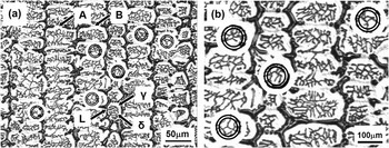
The as-quenched microstructure of AISI 304 stainless steel at the solidification stage is shown in Fig. 1(a). It can be seen that the lathy ferrite is arranged in an entangled cluster and is enveloped by austenite, which is the typical characteristic of peritectic transformation. Therefore, austenite, in the solidified microstructure, should originate from peritectic reaction. The two-phase microstructure is surrounded by the quenched liquid, as denoted by L in Fig. 1(a). As solidification proceeds, the surrounding liquid transforms into austenite gradually. This transformation can also be shown by Fig. 1(a), where austenite regions A and B are transformed from the initial retained liquid. On further cooling, more liquid transforms into austenite. When all the liquid is transformed into austenite, the solidification process is completed. From Fig. 1(a), it seems that the arrangement of the lathy ferrite is unorderly. However, some regular ferrite morphologies, such as “Y-shaped,” “V-shaped,” parallel, and perpendicular lathy ferrites can be observed in the solidified microstructure, as indicated by circles in Fig. 1(a). The magnified image of the “Y-shaped,” “V-shaped,” and perpendicular ferrite morphologies is shown in Fig. 1(b).
(a) As-quenched microstructure of Fe–Cr–Ni stainless steel during solidification (δ, γ, and L denote the entangled lathy ferrite, austenite, and quenched liquid, respectively) (“Y-shaped,” “V-shaped,” and perpendicular ferrites are denoted by circles) and (b) magnified image of the “Y-shaped,” “V-shaped,” and perpendicular ferrite morphologies.

To identify the phase constitution and determine the orientation relationship between ferrite and austenite at the solidification stage, TEM analyses were conducted. Figure 2 shows the TEM results of the entangled lathy ferrite formed during solidification. Figure 2(a) is a TEM micrograph of the “Y-shaped” ferrite. It is shown that the included angle among the elongated directions of the “Y-shaped” lathy ferrite is about 120°. To determine the crystallography, more than 15 composite selected area diffraction (SAD) patterns of ferrite and austenite were taken. Figure 2(b) shows a pair of diffraction patterns of the “Y-shaped” lathy ferrite and austenite. Based on the results in Fig. 2, it can be concluded that when lathy ferrite grows in a “Y-shaped” cluster, the orientation relationship between the lathy ferrite and austenite is  ${(\bar 110)_{\rm{\delta }}}$||
 ${(1\bar 11)_{\rm{\gamma }}}$and
 ${[001]_{\rm{\delta }}}$||
 ${[011]_{\rm{\gamma }}}$. Figure 3 shows the TEM results of the entangled lathy ferrite with another angle of incidence. Figure 3(a) is a TEM micrograph of the “Y-shaped” lathy ferrite. Figure 3(b) shows the crystallography between the “Y-shaped” lathy ferrite and austenite with
 ${[\bar 110]_{\rm{\delta }}}$||
 ${[1\bar 11]_{\rm{\gamma }}}$ zone axis. From Fig. 3, the orientation relationship between the lathy ferrite and austenite can be expressed as
 ${(002)_{\rm{\delta }}}$||
 ${(022)_{\rm{\gamma }}}$ and
 ${[\bar 110]_{\rm{\delta }}}$||
 ${[1\bar 11]_{\rm{\gamma }}}$.
TEM micrograph of the entangled lathy ferrite and the SAD patterns of lathy ferrite and austenite. (a) TEM micrograph; (b) SAD patterns with [001]δ||[011]γ zone axis showing the orientation relationship between the lathy ferrite and austenite.

TEM micrograph of the entangled lathy ferrite and the SAD patterns of lathy ferrite and austenite. (a) TEM micrograph; (b) SAD patterns with  ${[\bar 110]_{\rm{\delta }}}$||
 ${[1\bar 11]_{\rm{\gamma }}}$ zone axis showing the orientation relationship between the lathy ferrite and austenite.

IV. DISCUSSION
As mentioned above, entangled lathy ferrite morphology was observed in the solidified microstructure during directional solidification, as illustrated in Fig. 1(a). Furthermore, specific orientation relationship exists between the lathy ferrite and austenite. Thus, it is safe to infer that the orientation relationship between the lathy ferrite and austenite will determine the ferrite morphology during solidification for the Fe–Cr–Ni stainless steels. Therefore, we will reveal the formation mechanism of the entangled lathy ferrite in terms of the crystallography of the lathy ferrite.
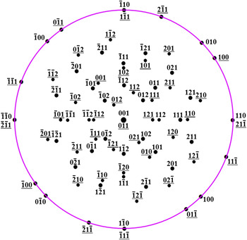
To obtain the detailed crystallography between the lathy ferrite and austenite, the orientation relationship is depicted on a stereogram, which is drawn so that  ${[001]_{\rm{\delta }}}$ and
 ${[011]_{\rm{\gamma }}}$ are coincident in the center, as shown in Fig. 4. Based on Fig. 4, the orientation relationship between the entangled lathy ferrite and austenite can be written as
 ${(\bar 110)_{\rm{\delta }}}$||
 ${(1\bar 11)_{\rm{\gamma }}}$,
 ${[110]_{\rm{\delta }}}$||
 ${[21\bar 1]_{\rm{\gamma }}}$, and
 ${[001]_{\rm{\delta }}}$||
 ${[011]_{\rm{\gamma }}}$. The
 ${(\bar 110)_{\rm{\delta }}}$ and
 ${(1\bar 11)_{\rm{\gamma }}}$ close-packed crystal planes are parallel to each other. This crystallography relationship is in agreement with the well-known Nishiyama–Wassermann relationship.
An overlapped stereographic projection of entangled lathy ferrite and austenite. (hkl) is the crystal plane of ferrite and (hkl) is the crystal plane of austenite.

For cubic systems, a crystal direction is perpendicular to the crystal plane with the same index. Therefore, two crystal directions are parallel to each other when the corresponding crystal planes are parallel. Thus, crystallography between the lathy ferrite and austenite in Fig. 4 can be divided into two types. First,  ${(\bar 110)_{\rm{\delta }}}$||
 ${(1\bar 11)_{\rm{\gamma }}}$ and
 ${[110]_{\rm{\delta }}}$||
 ${[21\bar 1]_{\rm{\gamma }}}$ lathy ferrite grows preferentially along
 ${[21\bar 1]_{\rm{\gamma }}}$ direction on
 ${(1\bar 11)_{\rm{\gamma }}}$ crystal plane. Second,
 ${(\bar 110)_{\rm{\delta }}}$||
 ${(1\bar 11)_{\rm{\gamma }}}$ and
 ${[001]_{\rm{\delta }}}$||
 ${[011]_{\rm{\gamma }}}$ lathy ferrite is preferentially elongated along
 ${[011]_{\rm{\gamma }}}$ direction on
 ${(1\bar 11)_{\rm{\gamma }}}$ crystal plane. Based on the elongated direction of the lathy ferrite, it can be inferred that atomic arrangement along
 ${[110]_{\rm{\delta }}}$ crystal direction on
 ${(\bar 110)_{\rm{\delta }}}$ plane must correlate with
 ${[21\bar 1]_{\rm{\gamma }}}$ direction on
 ${(1\bar 11)_{\rm{\gamma }}}$ plane. And the atomic arrangement along
 ${[001]_{\rm{\delta }}}$ direction must correlate with
 ${[011]_{\rm{\gamma }}}$ direction.
To examine the orientation relationship, we first show the array of atoms along  ${[21\bar 1]_{\rm{\gamma }}}$ on
 ${(1\bar 11)_{\rm{\gamma }}}$ plane and
 ${[110]_{\rm{\delta }}}$ on
 ${(\bar 110)_{\rm{\delta }}}$ plane, as shown in Figs. 5(a) and 5(b), respectively. To compare the atom spacing for the above two crystal directions, lattice parameters of ferrite and austenite are needed. We obtained the lattice parameters of ferrite and austenite using the diffraction angle and the crystal interplanar spacing in the x-ray diffraction patterns. The lattice parameters for ferrite and austenite are determined to be 0.2876 nm and 0.3592 nm, respectively.
(a) Schematic diagram of the atomic arrangement along  ${[21\bar 1]_{\rm{\gamma }}}$ direction in
 $(1\bar 11)$ plane of austenite; (b) schematic diagram of the atomic arrangement along
 ${[110]_{\rm{\delta }}}$ direction in
 $(\bar 110)$ plane of ferrite; (c) schematic diagram of the relationship between
 ${[21\bar 1]_{\rm{\gamma }}}$ and
 ${{\rm{[110]}}_{\rm{\delta }}}$ directions.

Based on the atomic arrangement for  ${[21\bar 1]_{\rm{\gamma }}}$ and
 ${[110]_{\rm{\delta }}}$, as schematically shown in Fig. 5(c), the misfit between the two directions can be calculated. The misfit can be expressed asReference Zou, Yang and Zhang30
 $${\rm{\alpha }} = {\raise0.7ex\hbox{${{{(\sqrt 6 {\rm{\alpha }}_{\rm{\gamma }} } \mathord{\left/ {\vphantom {{(\sqrt 6 {\rm{\alpha }}_{\rm{\gamma }} } 2}} \right. \kern-\nulldelimiterspace} 2} - \sqrt 2 {\rm{\alpha }}_{\rm{\delta }} )}$} \!\mathord{\left/ {\vphantom {{{{(\sqrt 6 {\rm{\alpha }}_{\rm{\gamma }} } \mathord{\left/ {\vphantom {{(\sqrt 6 {\rm{\alpha }}_{\rm{\gamma }} } 2}} \right. \kern-\nulldelimiterspace} 2} - \sqrt 2 {\rm{\alpha }}_{\rm{\delta }} )} {\sqrt 2 {\rm{\alpha }}_{\rm{\delta }} }}}\right.\kern-\nulldelimiterspace}\!\lower0.7ex\hbox{${\sqrt 2 {\rm{\alpha }}_{\rm{\delta }} }$}}\quad .$$
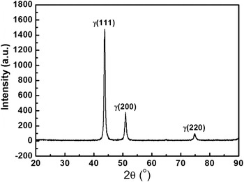
With the above lattice parameters, the misfit is calculated to be 8.2%, which is relatively low. It is well known that the interface between two phases can be divided into coherent interface, semi-coherent interface, and general interface. Interfacial energy can be reduced when the misfit between the two phases is decreased. To minimize the interfacial energy, a new phase will preferentially nucleate and grow along the directions with lower misfit. In the present experiments, the bottom of the sample does not melt and can act as a substrate for heterogeneous nucleation during solidification. The microstructure in the unmelted sample is composed of single-phase austenite, as confirmed by the x-ray diffraction patterns in Fig. 6.
X-ray diffraction patterns of the unmelted sample prior to solidification for Fe–Cr–Ni alloy, where only single austenite phase occurs.

When some crystal planes of austenite occur in the unmelted sample, ferrite will nucleate and grow preferentially along the directions with lower misfit. Therefore, ferrite should be preferentially elongated along  $[21\bar 1]$,
 $[\bar 112]$, and
 $[\bar 1\bar 2\bar 1]$ on
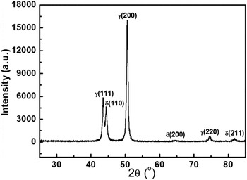
 ${(1\bar 11)_{\rm{\gamma }}}$. To analyze the crystallography and volume fraction of the lathy ferrite, XRD patterns of the directionally solidified sample were obtained, as shown in Fig. 7. It can be seen that (110) peak is the strongest peak for ferrite, which means that the majority of ferrite grows preferentially in the direction of
 ${[110]_{\rm{\delta }}}$. This preferential growth can be explained by analyzing the x-ray diffraction patterns in Fig. 6. From Fig. 6, it is clear that (111) peak of austenite is the strongest peak. This indicates that in the unmelted sample, most of the crystal planes are (111) plane and the resultant ferrite grows preferentially in the directions of
 $[21\bar 1]$,
 $[\bar 112]$, and
 $[\bar 1\bar 2\bar 1]$ due to lower misfit. This result can account for why entangled lathy ferrite dominates the whole lathy ferrite in the solidified microstructure. Based on the above analyses, it is not difficult to understand why ferrite formed on
 ${{\rm{(1\bar 11)}}_{\rm{\gamma }}}$ is elongated to form “Y-shaped” lathy ferrite, since the included angle between each pair of
 $[21\bar 1]$,
 $[\bar 112]$, and
 $[\bar 1\bar 2\bar 1]$ directions on
 ${(1\bar 11)_{\rm{\gamma }}}$ is 120°.
X-ray diffraction patterns of the directionally solidified sample for Fe–Cr–Ni alloy.

Using the same method, the misfit between  ${[001]_{\rm{\delta }}}$ and
 ${[011]_{\rm{\gamma }}}$ directions can also be obtained. The misfit can be expressed asReference Zou, Yang and Zhang30
 $${\rm{\alpha }} = {\raise0.7ex\hbox{${{{{\rm{(\alpha }}_{\rm{\delta }} - \sqrt {\rm{2}} {\rm{\alpha }}_{\rm{\gamma }} } \mathord{\left/ {\vphantom {{{\rm{(\alpha }}_{\rm{\delta }} - \sqrt {\rm{2}} {\rm{\alpha }}_{\rm{\gamma }} } {2)}}} \right. \kern-\nulldelimiterspace} {2)}}}$} \!\mathord{\left/ {\vphantom {{{{{\rm{(\alpha }}_{\rm{\delta }} - \sqrt {\rm{2}} {\rm{\alpha }}_{\rm{\gamma }} } \mathord{\left/ {\vphantom {{{\rm{(\alpha }}_{\rm{\delta }} - \sqrt {\rm{2}} {\rm{\alpha }}_{\rm{\gamma }} } {2)}}} \right. \kern-\nulldelimiterspace} {2)}}} {{{\sqrt 2 {\rm{\alpha }}_{\rm{\gamma }} } \mathord{\left/ {\vphantom {{\sqrt 2 {\rm{\alpha }}_{\rm{\gamma }} } 2}} \right. \kern-\nulldelimiterspace} 2}}}}\right.\kern-\nulldelimiterspace}\!\lower0.7ex\hbox{${{{\sqrt 2 {\rm{\alpha }}_{\rm{\gamma }} } \mathord{\left/ {\vphantom {{\sqrt 2 {\rm{\alpha }}_{\rm{\gamma }} } 2}} \right. \kern-\nulldelimiterspace} 2}}$}}\quad .$$
With the above lattice parameters, the misfit is calculated to be 13.2%, which is higher than the misfit between  ${[110]_{\rm{\delta }}}$ and
 ${[21\bar 1]_{\rm{\gamma }}}$ directions. This can help understand the XRD results in Fig. 7. From Fig. 7, it is clear that the intensity of
 ${(110)_{\rm{\delta }}}$ peak is much higher than
 ${(200)_{\rm{\delta }}}$ peak. This should be caused by the lower misfit between
 ${[110]_{\rm{\delta }}}$ and
 ${[21\bar 1]_{\rm{\gamma }}}$. Furthermore, the angle between each pair of
 ${[011]_{\rm{\gamma }}}$,
 ${[10\bar 1]_\gamma }$, and
 ${[\bar1\bar 10]_{\rm{\gamma }}}$ crystal directions is 120° as well. Thus, growth of ferrite along
 ${[011]_{\rm{\gamma }}}$,
 ${[10\bar 1]_{\rm{\gamma }}}$, and
 ${[\bar1\bar 10]_{\rm{\gamma }}}$ crystal directions can also form “Y-shaped” lathy ferrite. Therefore, “Y-shaped” lathy ferrite can be generated by the two preferential growths. It should be noted that the intensity of XRD is also a function of the multiplicity factor and the multiplicity factor of (110) is higher than (200) in cubic system. However, the difference in the multiplicity factor of the (110) and (200) planes cannot result in such a big difference in the diffraction intensity in Fig. 7. Furthermore,
 ${{\rm{(211)}}_{\rm{\delta }}}$ peak exists in Fig. 7, and this peak resulted from the occurrence of parallel lathy ferrite.Reference Fu and Yang31 The
 ${(211)_{\rm{\delta }}}$ peak is very weak because of lower volume fraction of the parallel lathy ferrite in the solidified microstructure.
To show this preferential growth, we obtain the growth direction of “Y-shaped” lathy ferrite using TEM, as shown in Figs. 2 and 3. It is confirmed that the elongated directions of the “Y-shaped” lathy ferrite are  ${\langle 211\rangle _{\rm{\gamma }}}$ and
 ${\langle 011\rangle _{\rm{\gamma }}}$ indeed. These results show that the analysis on the ferrite morphology and crystallography is reasonable.
Therefore, when  ${(1\bar 11)_{\rm{\gamma }}}$ acts as the substrate for heterogeneous nucleation, ferrite will preferentially grow in the directions of
 $[21\bar 1]$,
 $[\bar 112]$, and
 $[\bar 1\bar 2\bar 1]$ of austenite during solidification. In the same way, growth in the directions of
 ${[011]_{\rm{\gamma }}}$,
 ${[10\bar 1]_{\rm{\gamma }}}$, and
 ${[\bar 1\bar 10]_{\rm{\gamma }}}$ on
 ${[1\bar 11]_{\rm{\gamma }}}$ plane can occur. It is interesting to note that the angle between each pair of
 ${[011]_{\rm{\gamma }}}$,
 ${[10\bar 1]_{\rm{\gamma }}}$, and
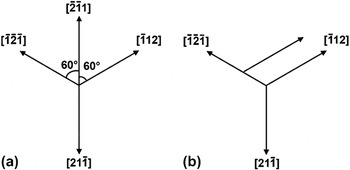
 ${[\bar1\bar 10]_{\rm{\gamma }}}$ crystal directions is also 120°. Therefore, preferential growth along these directions leads to the formation of the “Y-shaped” lathy ferrite. It should be pointed out that formation of the regular “Y-shaped” lathy ferrite is just for the case that only one austenite grain is considered. It is known that the rod comprises of many austenite grains before directional solidification. Thus, irregular lathy ferrite morphology will occur when several “Y-shaped” lathy ferrites intersect, as shown in Fig. 1. Furthermore, after carefully analyzing the lathy ferrite morphology in Fig. 1, we observed that 60° “V-shaped,” parallel, and perpendicular ferrite morphologies exist besides the “Y-shaped” lathy ferrite. Formation of “V-shaped” and parallel lathy ferrite morphologies can be schematically illustrated in Fig. 8. Figure 8(a) shows the formation mechanism of the 60° “V-shaped” lathy ferrite. It can be seen that when the lathy ferrite grows in the
 $[\bar 2\bar 11]$ direction, the negative direction of
 $[21\bar 1]$ makes an angle of 60° with both
 $[\bar 112]$ and
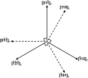
 $[\bar 1\bar 2\bar 1]$ directions. Likewise, 60° lathy ferrite can be formed in another two directions. Formation of the parallel lathy ferrite is caused by two or more lathy ferrites elongated in the same crystal direction, as can be illustrated in Fig. 8(b). Combination of the above three lathy ferrite morphologies can derive some other lathy ferrite morphologies, such as quadrangle, which can be found in Fig. 1(a). Furthermore, perpendicular lathy ferrite can also be observed in Fig. 1(a). Formation of this ferrite morphology can be understood by considering the geometrical relationship between
 ${\langle 211\rangle _{\rm{\gamma }}}$ and
 ${\langle 011\rangle _{\rm{\gamma }}}$ on
 ${{\rm{(1\bar 11)}}_{\rm{\gamma }}}$ plane, as shown in Fig. 9. It is apparent that some right angles exist between
 ${\langle 211\rangle _{\rm{\gamma }}}$ and
 ${\langle 011\rangle _{\rm{\gamma }}}$, which can account for the observed perpendicular lathy ferrite in Fig. 1(a). Therefore, though existence of multiform ferrite results in irregular and complicated ferrite morphologies in the solidified microstructure, we can still find the growth regularity. This growth regularity resulted from the intrinsic crystallography relationship between ferrite and austenite.
(a) Schematic for the formation of 60°; (b) the case of parallel ferrite.

Schematic for the formation of the perpendicular ferrite morphology.

Based on the above analyses, it is confirmed that the morphology of the entangled lathy ferrite depends on the crystallography of the lathy ferrite. The orientation relationship between the lathy ferrite and austenite is determined by the preexisting crystal plane of austenite. The occurrence of the preferential planes can be analyzed from the viewpoint of interfacial energy during solidification. For polycrystalline alloys, anisotropy, which resulted from different atomic densities in different orientations, is an important characteristic. According to Wulff theorem,Reference Wulff32 the crystal will adjust its interface shape to make the total interface energy minimum when the interface equilibrium is achieved. Thus, the solid/liquid interface is mostly composed of the close-packed plane and the second close-packed plane during solidification. For FCC metals or alloys, the close-packed plane is (111) plane and the second close-packed plane is (100) plane. Therefore, the two strongest peaks correspond to (111) and (100) planes, respectively, as shown in Fig. 6. Compared with the peaks of (111) and (100) planes, (110) peak is much weaker because the atomic density of (110) is lower than those of (111) and (100) planes.
V. CONCLUSIONS
The morphology of the lathy ferrite in the solidified microstructure depends on the orientation relationship between the lathy ferrite and austenite. It is confirmed by TEM that the lathy ferrite preferentially grows along  ${[21\bar 1]_{\rm{\gamma }}}$,
 ${[\bar 112]_{\rm{\gamma }}}$ and
 ${[\bar 1\bar 2\bar 1]_{\rm{\gamma }}}$ directions on
 ${(1\bar 11)_{\rm{\gamma }}}$ crystal plane because the misfit between
 ${[110]_{\rm{\delta }}}$ and
 ${[21\bar 1]_{\rm{\gamma }}}$ is much lower. Preferential growth of the lathy ferrite in the directions of
 ${[011]_{\rm{\gamma }}}$,
 ${[10\bar 1]_{\rm{\gamma }}}$, and
 ${[\bar 1\bar 10]_{\rm{\gamma }}}$ can also occur. Thus, “Y-shaped” lathy ferrite can be observed in the solidified microstructure because the included angle among the above crystal directions is 120°. When the negative directions of the above three directions are considered, 60° angle can be obtained, which leads to the formation of the “V-shaped” lathy ferrite. The relationship between
 ${\langle 211\rangle _{\rm{\gamma }}}$ and
 ${\langle 011\rangle _{\rm{\gamma }}}$ on the closed-packed plane of austenite leads to the perpendicular lathy ferrite morphology. The combination of the complex lathy ferrite accounts for the formation of the entangled lathy ferrite in the solidified microstructure.
ACKNOWLEDGMENT
This work was financially supported by the National Natural Science Foundation of China and Shanghai Baosteel Group Corporation (Grant No. 51004095).