

1 Introduction
Designing artificial intelligence (AI) planning and scheduling (P&S) systems able to support human activities in critical environments, for example, in space missions, is an important task that has been achieving increasing success during the last decade. Nevertheless, difficulties remain in the widespread utilization of such technologies outside the research laboratories. Let us just consider as an example the space applications, an area that generally introduces very challenging problems for P&S technologies. Very often, the proposed models and solutions turn out to be complex and even engineers, designers, and scientists have difficulties in validating and verifying them by simple inspection. For this reason, automated validation and verification (V&V) techniques may represent an important contribution, adding value to these kinds of applications provided they can be gracefully integrated with P&S technology (e.g. see Menzies & Pecheur, Reference Menzies and Pecheur2005). In fact, a failure on behalf of an automated decision support system may have a dramatic impact in terms of loss of science activities, money, and even human life.
It is worth reminding that validation allows us to check whether models, knowledge bases, and control knowledge accurately represent the knowledge as well as the objectives of the human experts that provided them (i.e. validation has to do with building the right system), while verification tells us whether the system (and its components) meets the specified requirements (i.e. building the system right).
Validation of planning models has been studied in several worksFootnote 1 and it is naturally considered as an important add-on technology for knowledge engineering environments. For instance, in the context of the Remote Agent Experiment, both Livingstone and RAX-PS domain models have been validated exploiting model checking techniques (Khatib et al., Reference Khatib, Muscettola and Havelund2001; Pecheur & Simmons, Reference Pecheur and Simmons2001); in Smith et al. (Reference Smith, Holzmann, Cucullu and Smith2005), formal verification is used to check the existence of undesirable plans with respect to the domain model; Simpson et al. (Reference Simpson, Kitchin and McCluskey2007) present an integrated tool for creation and validation of planning domains, while a plan validation tool for Planning Domain Definition Language (PDDL) is provided by Howey and Long (Reference Howey and Long2003). In Bensalem et al. (Reference Bensalem, Bozga, Krichen and Tripakis2005), Fox et al. (Reference Fox, Howey and Long2005), and Giannakopoulou et al. (Reference Giannakopoulou, Pasareanu, Lowry and Washington2005), formal methods are deployed to verify and validate plan execution and executive systems.
Current AI planning literature shows how timeline-based planning can be an effective competitor to classical planning in capturing complex domains that require the use of both temporal reasoning and scheduling features—see Muscettola (Reference Muscettola1994), Jonsson et al. (Reference Jonsson, Morris, Muscettola, Rajan and Smith2000), Smith et al. (Reference Smith, Frank and Jonsson2000b), and Frank and Jonsson (Reference Frank and Jonsson2003). Timelines represent entities whose properties vary in time, and represent one or more physical (or logical) subsystems relevant to the planning context. The timeline-based approach models the P&S problem by identifying a set of relevant features of the planning domain that need to be controlled to obtain a desired temporal behavior. A planner/scheduler is a decision-making software that synthesizes the controller for the temporal entities, and reasons in terms of constraints to bind the internal evolutions and desired properties (goals) of the generated temporal behaviors. Continuing our research line related to P&S with timelines, see Fratini et al. (Reference Fratini, Pecora and Cesta2008), we have implemented a reusable software framework (Cesta & Fratini, Reference Cesta and Fratini2008) for modeling and solving problems using the timeline-based approach. The resulting framework is the core software infrastructure on top of which, among others, a specific planner for the long-term planning (LTP) of the MarsExpress mission of the European Space Agency (ESA) has been developed. Such a special-purpose planner, called MrSPOCK for ‘Mars Express Science Plan Opportunities Coordination Kit’, is now in the phase of advanced testing in the ESA operational environment (Cesta et al., Reference Cesta, Cortellessa, Fratini and Oddi2009).
This paper describes our effort in exploring different perspectives in the integration of V&V with timeline-based P&S techniques. The long-term goal of this research is to synthesize a software environment in which both technologies are integrated, so that the application developers can take advantage of the coexistence of both previous tools, while encoding the knowledge of new applications. We present here a significant step in this direction consisting of adding V&V functionalities around the MrSPOCK specialized planner. In particular, we have added functionalities in order to perform both model V&V of the solutions found by MrSPOCK. To this purpose, we have considered and used two state-of-the-art formal verification tools, namely NuSMV and UPPAAL.
The rest of the paper is organized as follows. In Section 2, we introduce the target work on timeline-based planning and in particular the MrSPOCK system. In Section 3, we survey the possible use of V&V in planning systems. Section 4 presents V&V applied to MrSPOCK. Some discussion and conclusions end the paper.
2 The target planning system: MrSPOCK
The long-term goal we are pursuing is the integration of V&V techniques in a knowledge engineering environment for timeline-based problem solving. Little previous work exists that specifically concerns V&V in connection with this solving approach even if the relevance of V&V was strongly emphasized by the Remote Agent Experiment (e.g. Khatib et al., Reference Khatib, Muscettola and Havelund2001; Pecheur & Simmons, Reference Pecheur and Simmons2001). In this work, we illustrate a set of coordinated V&V interventions around a specific timeline-based planner developed for Esa, called MrSPOCK.
2.1 The problem and the required constraints
The MrSPOCK planner is developed to support LTP in the Mars Express mission at Esa. The mission consists of a spacecraft that has been orbiting around Mars since the end of 2003, returning a significant amount of data gathered by means of seven on-board payloads. The mission has been extremely successful in terms of scientific return and has also inspired a number of interesting work from the mission management point of view. An open problem was to improve the collaborative problem solving process between the science team and the operation team of the space mission. These two groups of human planners iteratively refine a plan containing all the mission activities. The mission planning process starts at the LTP level, that is, 3 months of planning horizon, and gradually boils down to obtain fully instantiated activities at the short-term plan level, that is, 1 week of planning horizon. The short-term plan is then further refined every 2 days to produce final executable plans. The goal of MrSPOCK is to develop a pre-planning optimization tool for planning spacecraft operations. Specifically, it focuses on the generation of a pre-optimized skeleton LTP, which will then be subject to refinement on behalf of the cooperative science team and the operation team (see Cesta et al., Reference Cesta, Cortellessa, Fratini and Oddi2008 for a detailed description of the addressed problem).
Broadly speaking, MrSPOCK has to provide an automated procedure for producing a good skeleton plan, that is, an LTP that takes into account the needs of both parties, thus reducing the effort in reaching an agreement on a medium-term plan—1-month planning horizon. Overall, the generated LTP should be such that (a) the number of (expensive) iterations between the science team and the operation team is reduced; (b) a set of objective functions are optimized, that is, the total volume of data for downlink operations; the number of pericenters for science operations; the number and the uniform distributions of uplink windows.
For each orbit followed by the spacecraft, the baseline operations are split identifying three orbit phases: (1) the pericenter (the orbital segment closest to the target planet); (2) the apocenter (the orbital segment farthest from the planet); (3) the orbital segments between the pericenter and apocenter. Around the pericenter, the spacecraft is generally pointing to the center of the planet, thus allowing observations of the planet surface—generically referred to as Science operations. Between the pericenter and apocenter passages, the spacecraft is generally pointing to Earth for transmitting data. Communication with Earth should occur within a ground station availability window. Ground-station visibility can either partially overlap or fully contain a pericenter passage. In addition, Maintenance operations should occur around the apocenter passages.
At present, given these requirements, an initial skeleton plan for Mars Express is generated by the operation team by allocating over the planning horizon (which generally covers hundreds of orbits) three different types of decisions:
• selection of the Maintenance windows (centered around the apocenter events and used primarily for momentum wheel-offloading);
• selection of the Communication windows among the set of available ground stations visibility windows;
• selection of the windows for Science operations, around pericenter events.
In addition, there are many hard and soft constraints to be satisfied. Constraints on uplink windows require four hours of uplink time every 24 hours (hard constraint), and these uplink windows must be as regular as possible, one about every 20 hours (this is formulated as a soft constraint since uplink windows require ground station availability, and it is generally impossible to state their positions exactly). Moreover, it should be given the possibility to split a 4-hour uplink window into two 2-hour uplink windows. Apocenter slots for spacecraft maintenance windows must be allocated between minimum two and maximum five orbits (hard constraint), and the maintenance duration is of 90 minutes (to be centered around the apocenter event).
Communication activities are the source of several hard temporal constraints. For example, (1) the minimum/maximal durations for the X-band transmitter in the on state; (2) the minimum duration for the X-band transmitter in the off state; (3) the periods in which the X-band transmitter has to be off (e.g. eclipses, occultations, slewing maneuvers, and non-Earth pointing status). Furthermore, there are preferences that should be followed for ground station selection (called de-overlapping in mission terminology). Ground stations have different features like different antenna diameters (there exist 70, 35, and 34 m dishes). Usually, antennas allow both uplink and downlink communications, but there are cases where downlink only is permitted.
2.2 The timeline-based approach
MrSPOCK is a timeline-based planner built using the modeling capabilities of a general-purpose software framework, named TRF (Timeline-based Representation Framework), which provides the basic elements for modeling the relevant entities for timeline-based problem solving (Cesta & Fratini, Reference Cesta and Fratini2008). The TRF is designed as a layered architecture: there is an underlying temporal database (that provides primitives to represent and manage time points and temporal constraints), a timeline management and representation layer above the temporal database (that provides primitives to represent temporal flexible plans as timelines), and an upper level that provides a unified and shared representation of both the domain theory information and the network of planning decisions. A portfolio of domain-independent P&S procedures is defined on top of the TRF along with a domain description language called ddl.3.
The timeline-based approach models the planning domain in terms of a set of temporal functions that evolve over a given temporal horizon. Examples of such functions are state variables that assume a discrete set of values respecting some transition laws (Jonsson et al., Reference Jonsson, Morris, Muscettola, Rajan and Smith2000) and resources as they are currently used in constraint-based scheduling (Cheng & Smith, Reference Cheng and Smith1994). These functions change by posting planning decisions. The domain theory specifies what can be done to change these evolutions, and the task of the planner is to find a sequence of decisions that bring the entities into a final situation, which verifies several ‘desired’ conditions (called goals). Unlike the classical approach, where the state of the world is changed by means of actions, in timeline-based planning, the posted decisions directly force value transitions in the specification of the relevant temporal domain features. The result of the planning process is called a timeline, or set of timelines, as it represents an evolution in time of the states of the physical system(s) modeled in the domain.
In the timeline-based solving approach, the planner decides in which states the world should find itself during given segments of the timeline (the planning decisions). During the solving phase, the planner operates on this temporally grounded representation of ‘what is happening’ in time. The timeline representation, in short, allows the planner to apply further decisions based on the consequences that these decisions have on the complete planning horizon. The progressive propagation of decisions determines how the entire timeline is affected. While in action-based planning the domain theory describes operators that change the state of the world, in timeline-based planning the domain theory represents how different decisions should be synchronized. This is represented through the notion of synchronization. Synchronizations describe the constraints that are imposed on the overall timeline when a specific decision is taken. For instance, a synchronization may state that a decision to ‘navigate to a destination’ needs to be synchronized with a decision to ‘consume a certain quantity of fuel’. As opposed to action-based planning, the focus here is on states rather than on the operators needed to change those states.
2.3 Modeling and solving the problem with timelines
The building of MrSPOCK has followed a hybrid approach. We have used (1) the timeline representation and management features of the TRF for the problem representation; (2) the capabilities of timeline planning from the general purpose P&S system called OMPS (Open Multi-component Planner and Scheduler—Fratini et al. Reference Fratini, Pecora and Cesta2008), also built on top of the TRF; (3) a domain-dependent solver that guarantees the satisfaction of the problem’s constraints not modeled in the domain description and that performs genetic-driven plans optimization, exploiting the domain-independent underlying planning system. More in detail, MrSPOCK uses (1) the modeling features of the TRF to represent timelines and some temporal constraints of the domain through the domain theory, as discussed below (operations duration as well as synchronizations among operations, such as sciences during pericenters, maintenance during apocenters, and communications during ground station visibility); (2) OMPS’s capabilities of planning and timeline manipulation to complete the partially specified plans produced by a domain-dependent solver designed on top of the TRF; (3) a domain-dependent solving procedure to build partial plans that take into account the constraints not modeled in the domain theory (like the minimum two to maximum five orbits separation constraint needed between two maintenance operations), and to also perform a genetic optimization of the partial plans produced.
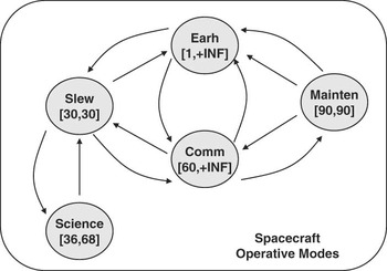
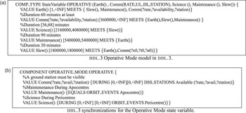
The TRF offers the possibility to model domains with two different types of timelines: (1) Controllable State Variables, which define the search space of the problem and whose timelines ultimately represent the solution to the problem; (2) Uncontrollable State Variables, which are used to inject temporal values that can be only observed. In MrSPOCK, we have used a single controllable state variable to model the spacecraft’s operative mode, which specifies the temporal occurrence of science and maintenance operations as well as the spacecraft’s ability to communicate. The values that can be taken by this state variable, their durations (represented as a pair [min, max]), and the allowed transitions among them are synthesized by the automaton in Figure 1, and represented in the ddl.3 specification as shown in Figure 3(a).
Legal transitions on the state variable describing the operational mode of the spacecraft

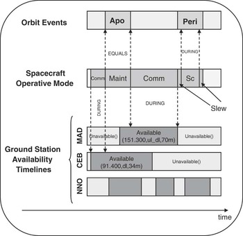
In addition, we instantiate two uncontrollable state variables to represent contingent events such as orbit events and communication opportunity windows. One state variable type component maintains the temporal occurrences of pericenters and apocenters (‘Peri’ and ‘Apo’ values on the timeline in Figure 2, top) of the spacecraft’s orbit (they are fixed in time according to the information found in an orbit events file), while the other state variables maintain the visibility of three ground stations (‘MAD’, ‘CEB’, and ‘NNO’ timelines in Figure 2, bottom). These state variables have {Available (?rate,?ul_dl,?antennas), Unavailable()} as allowed values, where the ?rate parameter indicates the bitrate at which communication can occur, ?ul_dl indicates whether the station is available for upload, download, or both, and the ?antennas parameter indicates which dish is available for transmission.
Timeline synchronizations

Any valid plan needs synchronizations among the operative mode timeline (Figure 2, middle) and the uncontrollable timelines (represented as dotted arrows in Figure 2 and as described in Figure 3(b) in ddl.3 specs): science operations must occur during Pericenters (meaning that a Science value must start and end during a Peri value), maintenance operations must occur in the same time interval as Apocenters (meaning that a Maint value must start and end exactly when the Apo value starts and ends), and communications must occur during ground station visibility windows (meaning that a Comm value must start and end during an Available value). In addition to those synchronization constraints, the operative mode timeline must respect the transitions among values specified by the automaton, as well as the minimal and maximal duration specified for each value (in the same automaton). It is worth remarking that in timeline-based planning, causal knowledge is modeled both in the value transitions specified by the automata and on the synchronizations constraints among the different automata of a domain.
ddl.3 specifications of a state variable and a synchronization constraint

On top of this representation, MrSPOCK’s solver builds the spacecraft’s operative mode timeline that allocates science, maintenance, and communication activities. A solution is obtained when a consistent timeline for the controllable component is defined and all the operational constraints represented by synchronizations are satisfied. A distinctive aspect of MrSPOCK is the direction we have taken to build a problem solver for the timeline representation: instead of using a generic search engine (for example, the P&S integrated search of OMPS), we have built a specialized solver that dialogues directly with the problem representation in the TRF. In this way, we exploit the TRF constraint engines for propagating several types of constraints, while using specialized search engines partly general (with OMPS) and partly tailored to the problem. In particular, MrSPOCK integrates a greedy one-pass constructive search procedure with a generic optimization cycle that uses a genetic algorithm approach as discussed in Cesta et al. (Reference Cesta, Cortellessa, Fratini and Oddi2008). The cooperation among different engines to build the solution within MrSPOCK is key to understanding the need of V&V procedures described in the following.
3 V&V issues for knowledge engineering planning systems
V&V techniques play an important role in the knowledge engineering process for model-based systems, and planning systems in particular, as they provide a way to assess the quality of the proposed requirements, models, and heuristics along with hints about how to rectify flawed solutions—see Preece (Reference Preece2001). As said before, validation allows us to check whether models, knowledge bases, and control knowledge accurately represent the aims and knowledge of the human experts who supplied it, while verification tells us whether the system (and its components) meets the specified requirements as a software artifact. V&V methods are also particularly important and challenging when deployed for the design of AI systems based on planning and execution (also referred to as model-based autonomous systems). Indeed, the quality and the reliability of these systems are very hard to assess due to the architectural complexity, the heterogeneity of semantics and of the algorithms involved, as well as the multitude of enabled behaviors—see Smith et al. (Reference Smith, Rajan and Muscettola1997) for a description of the knowledge acquisition process for models and heuristics of a complex autonomous systems based on P&S and Menzies and Pecheur (Reference Menzies and Pecheur2005) for a review of V&V problems and methods suitable for these systems.
In designing P&S-based systems, V&V can be applied at different stages of the knowledge engineering life cycle: domain validation, plan verification and validation, planner/solver validation and verification, and plan execution validation and verification. In the rest of this section, we introduce a quick review of several works that are relevant for each of these issues.
3.1 Domain validation
In P&S systems, the domain model plays a crucial role because the accuracy of the environment model has a direct impact on plan correctness (e.g. safety, liveness) and performance. In fact, while we can hope that a planner generates the correct plans for the given planning domain (environment model), unfortunately this is usually not straightforward. Because of modeling errors (e.g. inconsistent, incomplete, inaccurate models), the planning domain may not adequately represent the environment; hence, the resulting plans will be correct with respect to the planning domain, but of no use in the real world. For these reasons, validation of planning domains is a critical task that has been considered by several authors.
Domain validation aims at showing that no plan violating the given properties can ever be generated, given the planning domain. This can be performed by using testing or by using formal methods, for example, model checking. Testing can only show the presence of errors (i.e. if no error is found, there is no guarantee that none exists), whereas model checking can also demonstrate the absence of errors (i.e. if no error is found, we are guaranteed that none exists). Not surprisingly, model checking is computationally much more expensive than just testing since the former will look at all reachable states of the domain model. Since the number of such states is in general exponential in the domain size (state explosion), only moderate size domains can typically be handled using model checking techniques. In a testing-based approach, a large number of plans are generated and then checked to verify that each of them satisfies the given properties. Testing-based domain validation rests on plan verification and will be discussed in Section 3.2. In a model checking approach, a model checker is used to generate a plan that violates the given properties. If no such plan is found, then the planning domain is successfully validated; otherwise, the model checker returns a plan violating one of the given properties. Such undesired plans can be used to refine the planning domain. Domain validation starts again on such a new refined domain, until no more undesired plans are found by the model checker. In the following, we discuss domain validation based on model checking.
In the context of temporal planning, formal methods applied to validation of planning models are pioneered by Penix et al. (Reference Penix, Pecheur and Havelund1998) using three model checkers (SPIN, SMV, and Murphi) to inspect expressibility, liveness, and safety properties of simple planning domains for the HSTS planner (Muscettola, Reference Muscettola1994). In the same direction, a more expressive temporal model is considered by Khatib et al. (Reference Khatib, Muscettola and Havelund2001) who propose a mapping from interval-based temporal relations models (i.e. DDL models for HSTS) to timed automata models (UPPAAL). This mapping was introduced as a preliminary step toward the application of V&V techniques in timeline-based temporal planning; however, this direction has not been fully explored. Analogously, Vidal (Reference Vidal2000) presents a mapping from Contingent Temporal Constraint Network to Timed Game Automata models. Also, in this case, the authors propose the specification framework, but techniques for domain validation or temporal plan verification are not introduced. Formal methods for domain validation are proposed by Smith et al. (Reference Smith, Holzmann, Cucullu and Smith2005) and Havelund et al. (Reference Havelund, Groce, Holzmann, Joshi and Smith2008) using model checking (with SPIN) to guarantee that all plans enabled by the planning domain meet certain desired properties. If undesired plans are found, these are reported as errors and the planning domain has to be refined accordingly. It is worth noting that real-time temporal properties and temporally flexible plans are not addressed in such research work.
3.2 Plan verification
A typical approach to domain validation is the empirical evaluation (testing-based approach). Following this approach, a number of sample plans are generated and manually inspected to check for errors. For example, this is the method employed by Smith et al. (Reference Smith, Millar, Dunphy, Tung, Nayak, Gamble and Clark1999, Reference Smith, Feather and Muscettola2000a) in which hundreds of plans are selected to validate the domain model of the Remote Agent. Manual plan verification is a long, expensive, and error-prone activity. This has motivated research on automatic tools for plan verification. Note that plan verification can be used for (testing-based) domain validation as well as to show that the planner’s output is correct with respect to the given properties. This is much easier than showing the correctness of the planner itself.
Verification of temporal plans expressed in PDDL with durative actions is enabled by the VAL plan verification tool by Howey and Long (Reference Howey and Long2003) that has been used during International Planning Competitions since 2002. However, flexible temporal plans, complex temporal constraints, and other temporal features are still to be addressed (Fox et al., Reference Fox, Long, Baldwin, Wilson, Woods, Jameux and Aylett2006).
3.3 Plan synthesis
Generation of correct-by-construction plans from formal specifications have also been studied. For example, in Abdedaim et al. (Reference Abdedaim, Asarin, Gallien, Ingrand, Lesire and Sighireanu2007), the authors investigate and compare Constraint Based Temporal Planning techniques and Timed Game Automata methods for representing and solving realistic temporal planning problems. In this direction, they propose a mapping from IxTeT planning problems to UPPAAL-TIGA game-reachability problems and present a comparison of the two planning approaches.
Formal methods applied to timeline-based temporal planning are considered within the ANML framework, a timeline-based specification framework proposed at NASA Ames. For example, in Siminiceanu et al. (Reference Siminiceanu, Butler and Munoz2008), the authors present a translator from ANMLite (an abstract version of ANML) to the SAL model checker. Given this mapping, the authors illustrate preliminary results to assess the efficiency of model checking in plan synthesis.
It is worth saying that all these papers mainly focus on robust plan synthesis, while our aim in the current work is to address the V&V issues that arise when planning in complex domains with hybrid solvers.
3.4 Planner/solver validation and verification
Formal methods are mostly applied to model, plan, and plan execution validation and verification, while other methods are usually deployed for V&V of the planning engine. For example, the verification of the P&S system for the Remote Agent (Nayak et al., Reference Nayak, Bernard, Dorais, Gamble, Kanefsky, Kurien, Millar, Muscettola, Rajan, Rouquette, Smith and Taylor1999; Smith et al., Reference Smith, Millar, Dunphy, Tung, Nayak, Gamble and Clark1999; Jonsson et al., Reference Jonsson, Morris, Muscettola, Rajan and Smith2000) is based on test cases to check for convergence and plan correctness. More specifically, the P&S system is verified by generating hundreds of plans for a variety of initial states and goals, and using a plan checker to verify that the generated plans meet a validated set of plan correctness requirements.
A similar approach has been followed at JPL for validating the EO1-science agent (Cichy et al., Reference Cichy, Chien, Schaffer, Tran, Rabideau and Sherwood2005). One of the key issues in empirical testing is achieving adequate coverage with a manageable number of tests. Test selection should be guided by a coverage metric. However, classical approaches used for testing mission-critical systems are not suitable for planning systems (Jonsson et al., Reference Jonsson, Morris, Muscettola, Rajan and Smith2000) because of their complex search engines and rich input/output space. Within the IDEA framework, model checking techniques are used to explore the space of input scenarios in order to generate tests for the reactive planner (R-Moreno et al., Reference R-Moreno, Brat, Muscettola and Rijsman2007). It is worth noting that in this work, model checking is used to generate a representative set of off-nominal testing scenarios. In the same vein, we are interested in validating the overall P&S system. However, our focus is slightly different: we are mainly concerned with V&V formal methods for timeline-based planning systems that satisfy implicit domain constraints and are endowed with domain specific heuristics.
3.5 Plan execution verification and validation
V&V of plan generation does not guarantee robustness of plan execution. Indeed, a valid plan can be brittle at execution time due to environment conditions that cannot be modeled in advance (e.g. disturbances). V&V techniques can be also used for plan execution validation. For example, robust plan validation during execution is considered in Fox et al. (Reference Fox, Howey and Long2005) in which hybrid timed automata are deployed to handle plan validation with temporal uncertainty.
As a follow-up of the Remote Agent experiment, the work of Giannakopoulou et al. (Reference Giannakopoulou, Pasareanu, Lowry and Washington2005) describes a compositional approach to V&V applied to the NASA K9 Rover executive system, by deploying formal methods throughout the overall design and development life cycle. The plan execution for the K9 rover scenario is also considered in Bensalem et al. (Reference Bensalem, Bozga, Krichen and Tripakis2005). Here, a generated plan for the rover is transformed into timed automata. An observer is synthesized from the timed automata to check whether the sequence of observations complies with the specifications.
In Fox et al. (Reference Fox, Long, Baldwin, Wilson, Woods, Jameux and Aylett2006), the VAL framework, coupled with a plan execution architecture, has been applied to on-board plan verification and repair. In the CIRCA framework (Goldman et al., Reference Goldman, Musliner and Pelican2002), a Controller Synthesis Module (CSM) automatically synthesizes hard real-time reactive plans. The CSM is modeled using timed automata and a model-checking based plan verifier is used to support robust reactive planning. CIRCA’s main concern is the synthesis of control sequences on the fly. Accordingly, issues and methods (e.g. reactive plan generation and verification) are different from the ones discussed in the next section.
4 Verification and validation within MrSPOCK
The long-term goal of the authors is the definition of a general framework in which P&S and V&V technologies are strictly coupled. The main purpose is to provide a knowledge engineering environment for both developers and users of a P&S system. Potential benefits are twofold: on the one hand, developers can be supported by a tool that allows them to continuously check the correctness of their choices during all the design phases; on the other, users can increasingly build their trust in the application once endowed with an independent checker used to verify the generated solutions before the execution. Considering the issues introduced in Section 3, this framework aims at providing an integrated knowledge engineering support that exploits formal methods for domain validation, planner/solver V&V, and plan verification, thus supporting domain modeling, solver development, and application assessment.
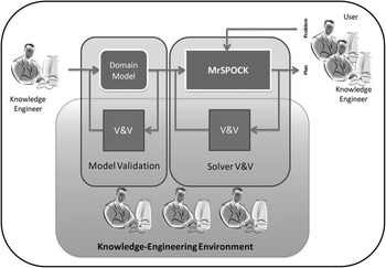
In the current stage of our work, we focus attention on the MrSPOCK planner, which has been developed for a real P&S space application. The goal is to provide an overall V&V framework for MrSPOCK. The whole approach can be seen as an incremental refinement process involving both model validation and planner V&V in which the deployment of formal methods is particularly important. Indeed, as already discussed in Section 2.3, the complexity of the domain and the hybrid solving process make very hard for the knowledge engineers to verify the solution generated by MrSPOCK. Figure 4 shows the overall knowledge engineering architecture built around MrSPOCK. Two main tasks are depicted: (a) Model validation; (b) Solver V&V. Model validation is the process of checking whether the domain model is well defined. In this case, our framework supports knowledge engineers in the process of refining and correcting the domain model with reference to the system requirements. Planner/Solver V&V allows users to check whether the solver works as expected. Design activities are supported by providing effective methods to verify the solver and the generated solutions. In particular, an important subtask of Planner/Solver V&V is plan verification, which systematically analyzes the solutions proposed by MrSPOCK. Indeed, errors possibly found in the generated plans could help knowledge engineers to revise the model (back to the model validation step), the heuristics, or the solver. Furthermore, plan V&V can also be exploited to analyze MrSPOCK’s plans with respect to the execution controllability issue as an additional verification step.
The knowledge engineering support architecture

The rest of this section describes in detail the current results: Section 4.1 discusses the general structure of the MrSPOCK V&V processes; Section 4.2 shows how MrSPOCK’s models can be validated; Section 4.3 presents planner validation; Section 4.4 shortly discusses a possible extension of these methods to manage flexible temporal plans. Moreover, interesting quantitative results are shown and discussed in Section 4.5.
4.1 Validating MrSPOCK via model checking
In the architecture of Figure 4, the V&V tasks are carried out using model checking technology. Model checking consists of a well-known set of techniques used to verify requirements and design properties for several real-time embedded and safety-critical systems. Generally speaking, a model checker (McMillan, Reference McMillan1993; Clarke et al., Reference Clarke, Grumberg and Peled1999) takes as input the system description and returns PASS if the system satisfies the given property, FAIL otherwise. In the latter case, the model checker also shows a system run (counterexample) that falsifies the given property. The system description is usually represented in a simple (concurrent) programming language. System properties are typically encoded in temporal logics such as CTL (Clarke et al., Reference Clarke, Grumberg and Peled1999) or Linear Temporal Logic (LTL; Holzmann, Reference Holzmann2004). It is worth reminding that (a) CTL (Computation Tree Logic) is a branching-time logic. Its model of time is tree-like: there are different paths in the future, each one representing a possible execution trace; (b) LTL is a modal temporal logic with a linear model of time. The main problem of model checking techniques is represented by state explosion because the number of reachable states of a system may be exponential in the size of the description of the system itself. Hence, the success of model checking rests on the fact that efficient techniques be devised to counteract the state explosion problem. The efficacy of the different approaches to model checking depends on the particular application domain. For this reason, many model checkers are available, each targeting a particular class of systems. In our current work, we use two prominent software tools, namely NuSMV and UPPAAL, both representing the state of the art in model checking technology, that offer remarkable features for our framework:
NuSMV (Cimatti et al., Reference Cimatti, Clarke, Giunchiglia, Giunchiglia, Pistore, Roveri, Sebastiani and Tacchella2002) is a model checker for concurrent (synchronous as well as asynchronous) Finite State Systems (FSS) employing temporal logics (CTL and LTL) to define specifications. The NuSMV modeling language allows definition of concurrent FSS in an expressive, compact, and modular way. The SMV model definition uses variables with finite types, grouped into a hierarchy of module declarations. Each module declares its local variables, their initial values, and how they change from one state to the next one. NuSMV is one of the most reliable model checkers available in the literature and its modeling language presents a high degree of expressiveness. Nevertheless, its modeling language does not provide specific constructs for time representation.
UPPAAL (Larsen et al., Reference Larsen, Pettersson and Yi1997) is a toolbox for specification, simulation, and verification of real-time systems. The verifier handles expressive safety and bounded liveness properties. A UPPAAL model consists of a set of timed automata, a set of clocks, global variables, and synchronizing channels. Each node of the automaton may be associated with invariants to enforce transitions out of the node. An arc may be associated with guards, for controlling when this transition can be activated. For each transition, local clocks may get reset and global variables may get reassigned. Channels can be used to synchronize transitions on different automata. As in NuSMV, the properties to be verified are defined using CTL. UPPAAL owns a temporal semantics that can be easily exploited during both modeling and verification.
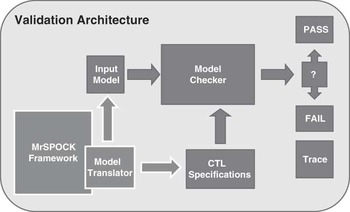
Validation architecture. The general validation architecture is designed as depicted in Figure 5. An automatic model translator embedded within the MrSPOCK framework is responsible for translating both models and solutions, and produces the specifications to be checked.
Validation architecture exploiting model checking

Recalling the validation processes introduced in Figure 4, model validation requires the translator to encode the MrSPOCK specification as an input model for the model checker along with the user queries (specified in CTL). On the other hand, plan verification needs an input model that encodes both the MrSPOCK model and the solution/plan, along with the plan property to be verified. Whenever the specification fails, the model checker provides an execution trace that can be exploited to understand if something is wrong or lacking.
Our V&V architecture is thus based on a well-suited mapping from the MrSPOCK domain and the generated plans to the input models needed by the model checkers. In the following section, we will describe in detail how the model translator automatically converts the MrSPOCK structures into the input model for the model checkers. Although the handling of parameters can be easily accommodated in our translation, the description of this aspect is omitted here for the sake of simplicity.
4.2 Model validation
The translation from a MrSPOCK model to a model checker formal model requires the introduction of a well-defined set of state variables and clocks. State variables range over domain states and model timelines, whereas clocks are used to represent time progression. For each state variable (and hence for each timeline), we have a state variable automaton whose states correspond to possible values of the state variable, while the transitions represent the value changes. In addition, we introduce another automaton, the observer automaton, that checks the consistency of the temporal constraints defined among different timelines. In the MrSPOCK domain, temporal constraints in the state variable definitions are specified by means of consistency features. Consistency features can be both value duration constraints (in the form of [min, max], for example, [90, 90] for maintenance activity), and sequencing constraints between values expressed by Allen’s temporal relations (e.g. Science meets Slew), while synchronization constraints, that is, constraints among different timelines, are expressed in terms of general temporal relations on values. In our specification, the latter are expressed and monitored by the observer automaton.
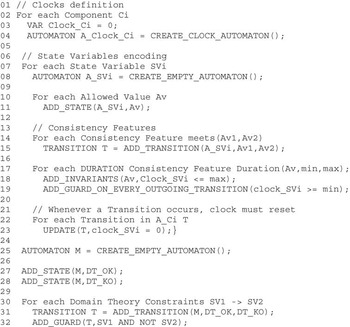
Figure 6 presents a mapping algorithm from the domain description of MrSPOCK to the input specification for the model checkers. This mapping works as follows. First, for each state variable we introduce a clock (rows 02–03). The clock is needed here to represent time and temporal constraints on the transitions. In addition, to model time progression, we introduce a clock automaton (row 04); whenever a transition occurs, the automaton resets the clock value to zero. Then, for each state variable, an automaton A_SVi is generated (rows 07–23) according to the set of possible values of the state variable and the related consistency features. Finally, we consider the synchronization constraints among different timelines. These relations present the following form: if the state variable SV1 evaluates to V1, then state variable SV2 is to be equal to V2. As already mentioned, these constraints are specified by an additional monitoring automaton, the observer automaton. More precisely, we generate an automaton endowed with two states (rows 25–32): the first state represents constraints satisfaction; the second one represents constraints violations. The transitions are as follows: initially, no violations occur; whenever a domain constraint violation is detected, we have a transition to the failing state.
An algorithm for mapping a timeline-based domain model into a model checkers model

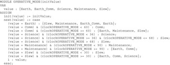
Two examples of consistency features related to the spacecraft’s operative mode are: science activity duration must be in [36, 68], and Maintenance task must meet Earth or Comm activity. In Figure 7, we show an excerpt of the derived NuSMV input model. The automata for Orbit Events and ground station availability are generated in a similar way. Note that, for each module, the initial state is given as a parameter, while transitions are omitted when associated with min = 1 and/or max = INF durations constraints. Here, the synchronizations between the Operative Mode timelines and the uncontrollable timelines compose the domain theory of MrSPOCK. More specifically, we have: science operations occurrences during pericenter orbits, maintenance operations during apocenter orbits, and ground station availability during communications. Figure 8 shows the definition in UPPAAL of the monitoring module.
NuSMV module definition for the OPERATIVE MODE state variable

UPPAAL monitor module definition. The monitor synchronizes transitions with state variable automata transitions through the pulse channel

Once the translated model is available as the input for the model checkers, the MrSPOCK model can be validated with respect to the properties and the requirements. For instance, we can verify that whenever a science activity is performed, results must be transmitted to Earth. This can be encoded through the following CTL formula: AG (OPERATIVE_MODE.value=Science) → AF (OPERATIVE_MODE.value=Comm).
This formula states that if a science activity is executed in a certain state, then in all the possible system executions originating from that state a communication task will eventually occur (coherently with the above requirement)Footnote 2.
Whenever the formula described above does not hold, a model checker produces an execution trace proving that the system reached an error state. The reported trace can be used to identify the domain inconsistency and to diagnose the conditions it originated from.
4.3 Planner validation
Planner validation is based on a plan verification tool that checks the solution generated by MrSPOCK with respect to the specified properties. Plan verification requires an input model that encodes both the MrSPOCK domain specification (described in the previous section) and the generated plan. In this case, the model checker can verify whether the generated plan is actually a good controller for the controlled systems. That is, the model checker verifies whether changes to plan executions and state variables can be synchronized or not.
First, we have to represent temporal plans in the model checker input specification. The plans generated by MrSPOCK provide a set of decisions/activations over the state variables. For each state variable, a generated plan provides a set of activations at fixed time points (planned timeline); therefore, a plan describes the sequence of values the state variables have to assume in a given time frame.
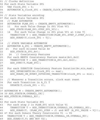
In Figure 9, we present an extension of the translating algorithm described in the previous section that allows us to encode the domain and the generated plan into a suitable input model for the model checkers. To represent the generated plan, we introduce an additional automaton (rows 06–16) for each state variable, representing the controller associated with the state variable. This automaton has a number of states that is equal to the length of the plan; for each activation/decision available in the plan, we introduce a state. Transitions between states represent plan steps, from the initial value to the last one. For each transition, we also introduce a guard that enables the transition at the time instant decided by the temporal plan.
The extended algorithm for mapping a timeline-based domain and plan model into a model checkers model

As for the model validation case, we maintain the specification illustrated in the previous section—for each state variable, we use the automaton described in the algorithm depicted in Figure 6—with the only expectation that in this case we also need to synchronize (row 27) the value changes occurring in the state variable automaton associated with the (controlled system), as well as the value changes occurring in the plan automaton (controller).
Finally, the observer automaton is also extended. Indeed, in this case we have to check not only domain constraints, but also the synchronization between the planned values (values defined in the generated plan) and the executed values (values assumed by the state variable). Therefore, in the observer automaton we introduce a new transition that triggers whenever a state variable value and the value decided by the planned cannot be aligned (rows 42–45).
Figure 10 illustrates a simplified NuSMV module for the extended monitor—here, we consider only a subset of the transitions associated with the Spacecraft Operative Mode state variable.
NuSMV module extended definition for monitor

Once the input model is completed and forwarded to the model checkers, we can formulate and verify the plan properties. In particular, using the observer automaton, the plan validity property can be formulated as follows: for each timeline, OK status for the monitor is always requested. This can be encoded by the following CTL formula: AG (Monitor.status=OVERALL_OK).
Whenever the above formula does not hold, the model checker reports an execution trace that allows the user to understand which inconsistencies are present between the planned timelines and the evolutions of the state variables. Thus, the reported trace can be used to identify plan errors and to diagnose the conditions they originated from.
Note that, when necessary, the observer automaton can become more complex to better support planner and model validation. For example, the observer automaton can be extended by introducing multiple error states, namely, we may introduce one error state for each relevant class of possible inconsistencies. In this way, the provided error type notion can be exploited in a subsequent refinement/correction of the domain, of the heuristics, or of the solver.
4.4 Flexible temporal plan verification
An interesting issue concerns the verification of flexible temporal plans. That is, plans where value changes can occur within time intervals rather than at fixed time instants. A flexible plan can be easily represented using the input model already described for plan verification. In this case, we simply have to consider temporal variables over a certain interval of values. That is, if a flexible time point of the plan can assume values in [Tmin, Tmax], then the associated temporal variable ranges over [Tmin…Tmax]. In this way, a model checker can explore and verify all the possible temporal evolutions of the flexible plan. By properly modeling the synchronizations among these variables, the domain state variables, and the plan behaviors, we can deploy the validation architecture presented above in several ways.
As a first step, we can check whether a flexible plan is dispatchable or not. In fact, we can ask the model checker to verify if there exists a possible temporal evolution of the plan guaranteeing that no constraint is violated. This can be encoded by the following CTL specification: EG (Monitor.status = OVERALL_OK). In addition, we can check several domain-dependent properties. This allows us to inspect properties of flexible plans before their execution. Typical properties are about accomplishment of tasks. For instance, we can check whether a flexible Science task can always be safely completed regardless of its start time. This can be encoded by the following formula: AG (OPERATIVE_MODE.status=Science → A (Monitor.status=OVERALL_OK U OPERATIVE_MODE.status=Slew)).
4.5 Lessons learned
Model checkers are extremely useful tools but the benefits of model checking come at a cost that can be very high. Menzies and Pecheur (Reference Menzies and Pecheur2005) identify the following three cost assessment phases: (a) Writing cost is the initial cost of developing the systems model and the properties model, in a format accepted by the model checker; (b) Running cost is the cost of actually running the model checker as many times as needed; (c) Re-writing cost is the cost of iteratively modifying the model until model checking can complete successfully and provide acceptable results. The exploitation of the knowledge engineering framework around MrSPOCK not only decreases the costs of using model checking tools but also provides useful support during the development process.
Basically, our framework minimizes the writing cost. In fact, the description of the system to be verified (domain model) is often translated by hand from its original design into the input syntax of the target verification tool. Usually, this translation is a time-consuming and error-prone human activity, typically taking weeks or months of human work.
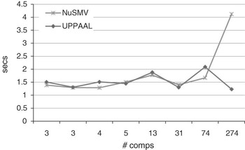
The model translation processes used within the MrSPOCK framework automates such translation, producing model checker input models in a matter of minutes. We have run our translator on several different domains in order to test the general behavior of the framework. We collected quite good performancesFootnote 3 depicted in Figure 11. Our experimental results show that, even handling domains with thousands of state variables, a few seconds are sufficient for our framework to produce domain models in both NuSMV and UPPAAL input languages.
Domain encoding times to UPPAAL and NuSMV input models

As a consequence of endowing our framework with automated V&V processes, another important advantage is granted. In fact, formal methods of expert interventions can be avoided, allowing field engineers to perform V&V tasks as part of the usual development process within the framework.
Concerning the running cost, we report some tests performed to assess plan validation performances in MrSPOCK. In particular, we validated plans generated by MrSPOCK ranging from 1 to 10 days of activity, handling from 45 to 335 tasks over all the timelines. The results, summarized in Figure 12, show that UPPAAL performs better than NuSMV (running BMC) on our examples. NuSMV proceeds by building a global state graph (or Kripke structure) in advance as a prerequisite for system properties verification, while UPPAAL works on the fly, as it is able to construct the global state graph dynamically. Moreover, UPPAAL exploits its internal temporal representation while NuSMV handles simple variables in order to model temporal clocks.
UPPAAL and NuSMV verification performances

Finally, the rewriting cost is not directly affected by framework functionalities, but the V&V processes presented above allow us to effectively support knowledge engineers in their work. Thus, both developers and users should be able to exploit the framework features to better analyze and understand the applications. For instance, the plan V&V tool allowed us to detect and solve a serious inconsistency in the MrSPOCK domain. In fact, the verification system actually discovered a previously unknown error: MrSPOCK could generate solutions not consistent with apocentre-maintenance occurrences constraint, which is an implicit requirement (i.e. not represented in the temporal model) for the hybrid solver. The execution trace allowed us to diagnose the inconsistency. Analyzing the problem, we found a subtle bug in the optimization process that caused the violation of the maintenance orbits distance constraint in the produced plans. We have been able to spot the problem during the plan verification task phase, and we were able to fix it by changing some optimization parameters.
5 Conclusion
V&V techniques play an essential role in knowledge engineering for model-based systems as they provide a way to assess the quality of the proposed requirements, models, and heuristics along with hints about how to amend flawed solutions. In this work, we have described our current approach to verify and validate both models and solvers for complex timeline-based planning systems. In particular, we have considered V&V issues focusing around the MrSPOCK system, a timeline-based planner developed for the European Space Agency, which has generated quite a number of research issues (Cesta et al., Reference Cesta, Cortellessa, Fratini and Oddi2008, Reference Cesta, Cortellessa, Fratini and Oddi2009).
The paper shows how V&V can be of practical impact in a P&S project. It is worth noting that the solving system of MrSPOCK is based on a hybrid approach: not all the domain constraints can be explicitly represented in the plan domain, and therefore the soundness of the generated plan with respect to the domain model does not necessarily ensure the soundness of the produced solution with respect to the real world. As opposed to other approaches in literature, in this context an independent solution verifier is needed not only for model validation and plan verification, but also to test the consistency of the generated plans with respect to the implicit requirements (e.g. those to be enforced by heuristics or optimization processes). In addition, from the end user perspective, V&V tools offer an independent testing environment that may enhance end users trust on the complex and (sometimes) counterintuitive solutions generated by MrSPOCK.
The paper describes a general V&V architecture for a state-of-the-art timeline-based planner. We show how such architecture is used to validate the MrSPOCK domain models and to verify its plans. Besides presenting the feasibility of the effort, we provide the description of the modeling and verification methods in detail. The experimental results show how the approach is quite effective. In particular, our translators from the MrSPOCK domain models to NuSMV or UPPAAL allow us to generate model checker inputs in a matter of minutes, whereas a manual approach may require weeks of error-prone human work. This allows system designers to save on the writing cost (Section 4.5). Running the verification shows that model checking time and memory usage for moderate size domains are quite acceptable. A tighter integration with the planner may improve this important aspect in the future. As for rewriting costs, we note that our V&V architecture spotted a subtle bug in the plan optimization process. Without such a framework, the bug could have gone undetected for quite a while and replicated by code reusing.
Acknowledgements
Cesta, Fratini, Orlandini, and Tronci are partially supported by the EU project ULISSE (Call ‘SPA.2007.2.1.01 Space Science’. Contract FP7.218815). Cesta and Fratini are also partially supported by European Space Agency (ESA) within the Advanced Planning and Scheduling Initiative (APSI). Thanks to Riccardo Rasconi for help in proofreading the paper.