Nomenclature
- a
-
speed of sound (m/s)
- A
-
area (m2)
- aux
-
vector of auxiliary flow variables
-
 $\mathfrak{A}$
-
Jacobian matrix of system of linearised equations
-
$\mathfrak{d}\mathfrak{q}$
-
vector of differential change in primary flow variables
- e
-
internal energy (J)
- f
-
real function with values in residuals, function of
- freevar
-
free variable in the system of simultaneous algebraic equations
- F
-
fluid force (N)
-
$\textrm{A},\;\left\{ {\dfrac{{\partial {F_i}}}{{\partial {P_i}}}} \right\}$
-
Jacobian matrix of residuals of conservation quantities
- h, H
-
enthalpy (J)
- i
-
iteration index, counter
- j
-
flow branch/pipe/link-set index
- k, m
-
node index
- l
-
suffix used to indicate the flow quantities evaluated in link/link-set
-
${\ell _1},\;{\ell _2}$
-
component of velocity normal to the surface
-
$\dot m$
,
$\dot w$
-
mass flow rate (kg/s)
- M, M a
-
Mach number
- M m
-
meridional momentum (N-s)
-
M
$_{\theta}$
-
tangential momentum (N-m)
- n
-
suffix used to indicate the flow quantities evaluated at a node
- N
-
number of nodes
- P, P s
-
static pressure (Pa)
-
$P_s^*$
-
static pressure based on sonic conditions (Pa)
- P 0 , P t
-
total pressure (Pa)
-
$\Delta {P_i}$
-
driving pressure difference at a node (Pa)
-
$\Delta {P_t}$
-
total pressure loss (Pa)
-
$\mathfrak{q}$
-
vector of primary flow variables
- qL, dqL
-
vectors of loss variables and their partial derivatives
-
$\bar{Q}$
-
mass mean averaged quantity
-
$\mathbb{q}$
-
vector of conservation quantities
- r, R
-
radius (m)
-
$\mathcal{R}$
,
$\Re $
-
vector of flow residuals
-
$\mathfrak{d}\mathcal{R}$
-
vector of small change in flow residuals
-
$\dot \Re $
,
$\mathfrak{d}\dot \Re $
-
vector of time rate change of residuals and their derivatives
- s, S
-
entropy (J)
- t
-
time (s)
-
-
component of velocity tangential to the surface
- T, T s
-
static temperature (K)
-
$T_s^*$
-
static temperature based on sonic conditions (K)
- T 0 , T t
-
total temperature (K)
-
$\Delta T$
-
driving temperature difference at a node (K)
- T q
-
torque exerted by or on the fluid (N-m)
- u m
-
meridional velocity (m/s)
- u θ
-
tangential velocity (m/s)
-
$u_m^{\ast}$
-
sonic meridional velocity (m/s)
-
$u_{{\theta }}^{\ast}$
-
sonic tangential velocity (m/s)
- V
-
cavity volume (m3)
-
$\left\{ {\Delta X} \right\}$
-
vector of unknown incremental parameters


Greek Symbol
-
$\rho $
-
fluid density (kg/m3)
-
$\Delta$
-
small change
-
$\partial $
-
operator of partial derivatives
-
$\Delta \tau $
-
small time change, flow residence time (s)
-
$\sigma $
-
courant number, CFL number
-
${\mathfrak{S}^R}$
-
spectral radius


Subscripts/Superscripts
- *
-
sonic flow quantities
- 0
-
total quantities
-
$\cdot$
-
time rate of change of a flow variable
- cavity
-
flow quantities pertaining to a cavity/node
- exit
-
exit station
- in/out
-
incoming/outgoing flow at a node
- links
-
flow quantities pertaining to a link-set
- loss
-
loss quantity
- prim
-
primary flow quantities
- sonic
-
sonic flow quantities
- sec
-
secondary flow quantities
- vect
-
vector of loss quantities

Abbreviations
- 1D, 2D, 3D
one dimensional, two dimensional and three dimensional
- CAD
computer aided design
- CFD
computational fluid dynamics
- GA
general assembly
- GUI
graphical user interface
- HP ROTORS
rotor of high-pressure spool
- IPC
intermediate pressure compressor
- IP ROTORS
rotor of intermediate-pressure spool
- LHS
left-hand side (of equation)
- LINK-SET
set of links connected in series
- LP ROTORS
rotor of low-pressure spool
- RHS
right-hand side (of equation)
- SAS
secondary air system, internal air system
- SFC
specific fuel consumption
- STATORS
stators of high, intermediate and low-pressure spools
1.0 Introduction
Performance and mechanical integrity are the key technical considerations that drive the design and development of aero engine modules. These considerations are quantified through the parameters, such as reduction of specific fuel consumption (SFC), reduced emissions, avoiding of the high-cycle and low-cycle fatigue failures and improved component life. The process control parameters such as, design lead time and the design and development time-cost are also critical to remain commercially competitive in the demanding market of gas turbine engines. These fundamental considerations and parameters govern the design and development of the secondary air system (SAS) of gas turbine engine and those must be applied during each phase of SAS development.
The secondary air system of a gas turbine engine is composed of diverse air streams passing through various engine modules. These air streams are generated due to the flows leaking between stationary and rotating parts of the primary air system. While these internal flows are parasitic to the engine performance, they perform vital functions such as cavity ventilation, cooling flow supply, flow metering, flow sealing, cavity pressurisation, thrust load balancing and de-icing etc. The unhindered operation of SAS is critical to maintain the engine performance and to ensure its mechanical integrity in various operating conditions. Clearly, a poorly designed SAS can heavily penalise the engine performance by increasing the SFC and by reducing the rated thrust; and can also reduce engine life and availability due to poor cooling and heat management issues. The system-level design of SAS, therefore, must satisfy various performance, mechanical integrity, safety, cost and design-manufacturing timescale requirements.
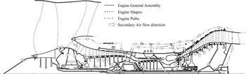
Figure 1 shows the schematic representation of secondary air flows in a typical three-spool aero gas turbine engine. The SAS design, particularly its topology and expanse, are defined by the overall architecture of an engine, whereas its minuscule geometric details are defined by the assembled geometric outlines of various structural components [Reference Moore1, Reference Zimmermann2] and the manufacturing limitations. As a result, every time the engine topology is modified or the structural design of a component is updated, the SAS design changes. This design dependency can, therefore, generate myriad design configurations for a given engine architecture. Clearly, the SAS design evolves slowly by balancing and satisfying various requirements of the key technical and process parameters.
A schematic representation of secondary air flows in a gas turbine engine [Reference Kulkarni17].

1.1 SAS design-simulation approaches
At present, the preliminary SAS designs are generated using 1D system-level flow network simulation approach [Reference Zimmermann2–Reference Muller8] across the gas turbine industry. In this approach, a given SAS design is represented in the form of nodes and links of a low-fidelity flow network model. A node represents a lumped, finite air volume of a large cavity in engine, whereas a link represents a flow path that connects those cavities. The interconnecting flow paths represent the air system components such as orifices, seals and pipes. Multiple links are used to represent long flow paths comprising several SAS components, such as pipes, valves and other hydraulic devices such as gradual and sudden contraction and expansion joints, bends, disc bores, couplings and cooling passages.
The low-fidelity flow network models are usually constructed and modified via graphical user interface (GUI). They are iteratively solved by adjusting the pressures and temperatures at all non-boundary nodes until the mass flow rates and their directions are balanced in all links. The results of these quasi-steady and transient aero-thermo-mechanical simulations are used to understand the SAS component interactions and to predict the engine performance at multiple operating points.
Since the past decade or so, 2D/3D CFD-based SAS models have been generated [Reference Gallar, Calcagni, Pachidis and Pilidis9–Reference Wang, Carnevale, Lu, di Mare and Kulkarni15], which usually represent a partial SAS configuration. These high-fidelity models are used in the gas turbine industry for SAS design-analyses, for developing specialised components, for designing localised geometry features and for coupling the SAS analyses with other high-fidelity simulations. Fully coupled SAS-primary air flow path configurations have also been developed, but they are usually employed for the research-based studies. CFD-based simulations, however, are rarely used to simulate the whole secondary air system of a gas turbine engine.
Whether using low-fidelity whole-SAS flow network modelling approach or the high-fidelity partial SAS CFD modelling approach, significant efforts are still required to configure the geometries, to prepare the models, to generate the meshes and to apply the boundary conditions. These manual processing steps require exhaustive human intervention and monitoring at each step, which consume approximately 70% of SAS design and analysis time. A study shows that SAS modelling workflow has four main limitations, namely repetitiveness, high time-cost, inefficiency and no value addition [Reference Peoc’h16]. These limitations make the conventional SAS model generation and processing highly labour-intensive and prone to human errors. These inefficient and unautomated process steps lead to the accumulation of unnecessary, non-value adding activities in the SAS modelling workflow. Moreover, despite involving a great deal of expertise and experience, these manual processing steps do not often bring any specific knowledge or add value in the SAS design development. The success of both the flow network and CFD analyses also completely depends on the correct execution of these process steps. Such process bottlenecks in SAS design-analysis shows the necessity and the value in automating the SAS design-simulation workflows.
The solutions to overcome the limitations of SAS design-simulation process are to:
-
develop a pre-determined set of rules or heuristics to quickly generate the SAS design-analysis models from the pre-existing geometry models
-
re-engineer the SAS model generation process steps and to automate them using the new agile software design philosophy
-
build an associative object-oriented framework to fetch the parametric and performance metadata into the model
This paper describes a novel SAS flow network modelling approach, wherein the whole-engine flow network model is automatically generated from an existing feature-based computational geometry model of a gas turbine engine based on a pre-determined set of rules. This approach employs new agile design philosophy and a re-engineered SAS workflow to pre-process the flow network model within a few minutes without any human interference. It also automatically fetches and applies the flow and rotational speed boundary conditions from the engine performance model through an associative object-oriented framework. This overall SAS design-simulation approach is implemented within an in-house design-simulation environment – Virtual Gas Turbines [Reference Kulkarni17–Reference di Mare, Kulkarni, Wang, Romanov, Ramar and Zachariadis19]. Virtual Gas Turbines is an object-oriented [Reference Geelink, Salomons, van Slooten, van Houten and Kals20, Reference Liang and O’Grady21], largely parallelised and extensible computational platform [Reference Connacher, Jayaram and Lyons22–Reference Libardi and Dixon26] with modular architecture [Reference Shah, Urban, Raghupathy and Rogers27] that is especially developed for simulating the virtual operation of a gas turbine engine. These capabilities allow the development of multi-disciplinary, multi-objective design-optimisation workflows, such as the present SAS flow network modeller, and hence offer great advantages to reduce the overall design time-cost and to make fully coupled, system-level design-analysis simulations affordable in real-time design process. This approach and its automated pre-processing steps are summarised in the next section.
1.2 Automated generation of SAS flow network model
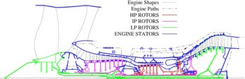
The Virtual Gas Turbines design-simulation environment incorporates an in-built feature-based 2D/3D geometry modeler, which is elaborated in Refs. [Reference Kulkarni17, Reference Kulkarni and di Mare18, Reference di Mare, Kulkarni, Wang, Romanov, Ramar and Zachariadis19, Reference Kulkarni, Lu, Wang and di Mare28, Reference Kulkarni, Lu, Wang and di Mare29]. This geometry modeller is built upon three fundamental data structures, namely features [Reference Shah and Mantyla30], shapes and paths, which can encapsulate a variety of geometric and non-geometric information and produce parameterised 2D/3D geometry models. It consists of four core modules, namely a library of geometry features to represent a variety of turbomachinery components, a geometry kernel to perform all geometric operations, a set of inter-feature relationship methods to determine the feature behaviours and interactions in complex geometry models and a recursive assembly modeller to build a top-down, logical structure of features representing the geometry of a whole gas turbine engine. Figure 2 displays the multi-layered general assembly (GA) model of a three-spool gas turbine engine. It consists of top-level abstract geometry features representing entities such as engine, spool, module and blade and the lower-level detailing features representing entities such as seals, bearings, orifices, slots, pipes, valves etc. This model is assembled to have a tree-like arrangement of features that preserves the design intents within multiple layers of abstraction throughout the design process. Thus, it allows the design to be modified freely and supports the propagation of design intents throughout the geometry model automatically.
The dynasty-based feature assembly of a three-spool gas turbine engine [Reference Kulkarni17, Reference Kulkarni, Lu, Wang and di Mare28, Reference Kulkarni, Lu, Wang and di Mare29].

Figure 2 demonstrates the unique spool-wise modular assembly of feature groups [Reference Kulkarni17, Reference Kulkarni, Lu, Wang and di Mare28, Reference Kulkarni, Lu, Wang and di Mare29]. In such a feature grouping, spool and module features are created at a higher level of abstraction and the lower-level features representing various engine components are attached to their respective spool family. The ancestor spool feature holds a modifiable rotational speed parameter that can be inherited by all lower-level features in its grouping. Such feature groupings are termed as speed dynasties. This kind of feature tree construction is convenient to ensure that each feature and its geometry model gets a consistent rotational speed boundary condition each time the analysis conditions are updated. The geometry modeller also automatically tags each edge of the feature geometry models [Reference Kulkarni17, Reference Kulkarni, Lu, Wang and di Mare28, Reference Kulkarni, Lu, Wang and di Mare29], which makes them traceable and identifiable during the downstream processing and analyses.
The feature-based geometry model generated by the geometry modeller is transformed into a SAS flow network model. An overall workflow chart summarising the transformation steps is displayed in Fig. 14 (see Section 4.0) and its reduced version can be found in Refs. [Reference Kulkarni and di Mare31, Reference Kulkarni and di Mare32]. In the first step, 2D cavity polygons are extracted from the engine GA model using a set of aerodynamic boundaries, which are typically located at seal clearances or similar locations. The user needs to supply the tags of aerodynamic boundaries to define the expanse of the SAS model. A polygon slitting algorithm [Reference Bose, Czyzowicz, Kranakis, Krizanc and Maheshwari33, Reference Chazelle34] is employed to extract the cavities and flow paths as shown in Fig. 3. More details are provided in Refs. [Reference Kulkarni17, Reference Kulkarni and di Mare31, Reference Kulkarni and di Mare32]. The polygon slitting algorithm allocates a global number to each cavity and to the links that interconnect them; thus, generating the flow network connectivity table.
Extraction of cavities and flow paths from whole-engine geometry model [Reference Kulkarni17].

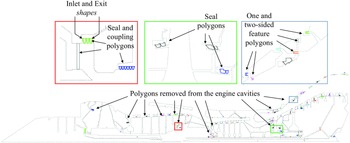
In the second step, the extracted cavity polygons and flow paths are identified and processed. For example, as shown in Fig. 4, the polygon splitting algorithm generates an outermost polygon that envelops the selected SAS domain. This outermost polygon is identified and removed from the set of cavity polygons. The locations, where the outermost polygon is connected to the extracted cavity polygons, are identified as the flow boundaries of the SAS model. This rule-based workflow also identifies the non-SAS cavities, such as bearing chambers and gearbox cavities (see Fig. 4) and removes them from the set of cavity polygons [Reference Kulkarni17, Reference Kulkarni and di Mare31, Reference Kulkarni and di Mare32].
Identification of engine cavities and flow-paths [Reference Kulkarni and di Mare32].

In the third step, the flow network modeller removes small internal cavities that are not ventilated by the secondary air flows, as shown in Fig. 5. It also replaces the cavities generated by specialised features, such as seals, with corresponding flow links [Reference Kulkarni17, Reference Kulkarni and di Mare31, Reference Kulkarni and di Mare32]. The flow network connectivity table is updated to account for the removal of cavities and the addition of new links.
Addition of SAS components in engine dressing and link processing [Reference Kulkarni and di Mare32].

In the fourth step, the flow network modeller reads a list of paths representing blade passages and other SAS components such as, pipes, manifolds, valves, expanders, nozzles etc. It adds these paths as new flow links and also adds junction polygons in the set of cavity polygons. Further, the algorithm searches for the cavities [Reference Kulkarni and di Mare31, Reference Kulkarni and di Mare32] that are connected through pipe paths. If found, those new cavities are also added into the set of cavity polygons and the connectivity table is amended. In this step, the flow network modeller also adds the paths of flow passages in cooled blades. If such a path opens outside the SAS model, then a boundary type node is created at that opening location. The flow network connectivity table is amended to register these new nodes and flow links.
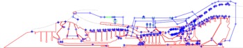
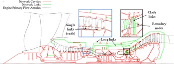
In the fifth step, a unique capability of this automated flow network modeller is utilised to assemble the long flow-paths in engine dressing module. The modeller makes use of inter-feature connectivity [Reference Kulkarni17, Reference Kulkarni, Lu, Wang and di Mare28, Reference Kulkarni, Lu, Wang and di Mare29] information between SAS features and builds its representative long flow-link by successively adding its paths and polygons. More details are provided in Refs. [Reference Kulkarni17, Reference Kulkarni and di Mare31, Reference Kulkarni and di Mare32]. Finally, the visualisation method of this SAS modeller collects the geometric descriptions of all cavity polygons, boundary node polygons and flow-paths in the form of their key points. The visualisation method [Reference di Mare, Kulkarni, Wang, Romanov, Ramar and Zachariadis19, Reference Kulkarni and di Mare31, Reference Kulkarni and di Mare32] assembles both cavity polygons and SAS links and generates a graphic image of flow network model. Figure 6 shows an automatically generated low-fidelity flow network model of secondary air system components from the feature-based geometry model of a three-spool gas turbine engine.
Visualisation of the flow network model consisting of cavities and flow-paths [Reference Kulkarni and di Mare31, Reference Kulkarni and di Mare32].

1.3 Objectives
The automated SAS model generation methodology described here seamlessly integrates the geometry modeller with the flow network modeller of Virtual Gas Turbines design-simulation environment. It establishes bi-directional information exchange between these two application spaces through database enquiry methods; thus, generating powerful feedback and feedforward data transfer mechanisms. This unique capability also allows automatic updating of SAS component designs based on the SAS analysis results [Reference Kulkarni and di Mare31, Reference Kulkarni and di Mare32]. The SAS component geometry changes automatically propagate in the general assembly model of engine due to its feature-based construction. This capability is deemed necessary to create a fully integrated software that can automatically perform SAS design-optimization.
This automated methodology, however, requires a compatible SAS flow network solver to conduct the SAS analyses at multiple engine operating points. It is observed that the flow network solvers available commercially are either not compatible or not automated to a requisite level to undertake such tasks. Therefore, these automation steps are supplemented by an innovative, hierarchical SAS flow network solver that is designed to be compatible with this overall SAS design-analysis-optimization approach. This paper further describes the construction and mathematical formulation of in-house SAS flow network solver, which is embedded into the flow network modeller of the Virtual Gas Turbines design-simulation environment.
1.4 A Survey of flow network solvers
Suntry [Reference Suntry35] had proposed one of the earliest flow network solvers, which was based on a few simple flow elements. This solver was useful for conservative engine design tasks during early periods; however, it lacked temperature prediction capability and thus it could not estimate heat flux in cavities.
Rose [Reference Rose4] had proposed a mathematical scheme for the secondary air system network solver – FLOWNET. This relatively simple flow network solver considers only three types of flow links, namely; face seals, narrow slots and pipes. It is based on certain assumptions such as, (i) a node represents a pressure chamber, which can have several inlet and outlet connections, (ii) no loss of mass flow exists and the flow velocities in pressure chamber are negligible, (iii) a unique steady state solution always exists, (iv) fluid temperature at each node is known and there is no heat transfer in the flow network. Rose’s flow network algorithm [Reference Rose4] solves conservation equations to calculate the mass flow rate in each link, which is the function of pressure and temperature,
 ${\dot m_{i,k}} = f\left( {{P_i},\;{P_j},\;T} \right)$
at its inlet and exit nodes. Least-square method was employed to minimise the sum of square of mass flow rate residuals. This iterative process of computing link mass flow rates and correcting node pressures continues till the convergence criterion shown in Equation (1) is satisfied,
 \begin{align}R \equiv \;\mathop \sum \nolimits_{all\;nodes} R_k^2 = \left| {\frac{{P_k^{\left( i \right)} - \;P_k^{\left( {i + 1} \right)}}}{{P_k^{\left( i \right)}}}} \right|\; \le \;{\left( {\Delta P} \right)_{{\textrm{max}}}}\end{align}
The mass flow functions in FLOWNET [Reference Rose4] consist of complicated non-linear loss model correlations and their partial differentials are obtained from simple pressure ratio-based model functions. As a result, the partial derivatives of mass flow function can be written as ordinary derivatives of model function. The problem thus reduces to solving a set of simultaneous linear equations.
FLOWNET also includes a few additional features such as, improvement in solution accuracy in the vicinity of converged solution, handling of flow reversal situations and plug-in facilities for user defined functions. This approach is fairly attractive for implementation, but it may fail in the events such as singular matrix or while obtaining the direction of steepest gradient.
Kutz et al. [Reference Kutz and Speer5] proposed a more generic SAS flow solver. Their computational scheme consists of four hierarchical iteration loops namely,
-
(i) a nodal temperature loop, which iterates on nodal temperatures considering the heat fluxes through cavity walls
-
(ii) a nodal pressure loop, which iterates on nodal pressures based on mass flow rate variation in each branch of flow network
-
(iii) a branch/pipe flow loop, which computes mass flow rate through each branch of flow network
-
(iv) a loss loop, which computes flow losses in SAS elements as their boundary conditions change
Kutz et al. [Reference Kutz and Speer5] contend that using a hierarchical equation solver is useful to decouple the variation of nodal temperature within the flow network from that of pressure. This solver construction is contended to be valid as nodal temperatures have a weak effect on nodal pressures and thus on the mass flow rates through the flow links. As a result, nodal pressures can be computed using simpler matrix-based simultaneous equation solver, shown in Equation (2). Note that Equation (2) is solved for all flow network branches.
 \begin{align}{\left\{ {\mathop \sum \limits_{i\;\,for\;\,Pipe\;\,j} {{\dot m}_i}} \right\}_{N\;Array}} = {\left\{ {\frac{{\partial {F_i}}}{{\partial {P_i}}}} \right\}_{N\; \times N\;Jacobian}}{\left\{ {\Delta {P_i}} \right\}_{N\;Array}}\end{align}
During each solver iteration, the initial nodal pressures are used to calculate the mass flow rate through each SAS element of each branch of network. The mass flow rate is calculated from the downstream end of flow branch, which is suitable for the choked flow links. After computing all mass flow rates and the partial derivatives of flow losses, the matrix shown in Equation (2) is solved for obtaining nodal pressures. This process is repeated until getting a converged solution. Note that the solver formulation proposed by Kutz et al. [Reference Kutz and Speer5] requires two different forms of every loss model – one for computing mass flow rate based on inlet and exit pressures, and another for computing inlet pressure from the guess values of mass flow rate and exit pressure. The preparation and maintenance of each form of these loss models is a labourious task. Moreover, their formulation assumes decoupling of energy and momentum equations, which is a major limitation.
Foley [Reference Foley3] stated that the air system design gets a retrospective treatment and hence it cannot be synthesised in a way similar to other engine components. He proposed a different technique to evaluate the effects of SAS modifications on the engine performance without actually running the whole engine performance computations. His method is not strictly related to the formulation of flow network solver; however, it can be used for performing a quick assessment of air system modifications such as, change of air-bleed locations in compressor and air re-entry locations in turbine using SAS network solver. This method can provide a quick and accurate estimate of performance variation, and hence the air system design modifications can be accepted or discarded justifiably.
In recent years, Muller [Reference Muller7, Reference Muller8] had proposed one of the most prominent approaches to the construction of secondary air system solver. His flow network solver is principally designed to couple with a finite element solver to conduct the thermomechanical analysis. Muller [Reference Muller7, Reference Muller8] defined each flow element by a triplet of nodes, such as an inflow node, middle or element node and an outflow node. His solver incorporates conservation equations of mass, momentum and energy that are expressed in terms of total pressure, total temperature and mass flow rate. He assumed that these equations, particularly the momentum equation, are differentiable with respect to primary variables over the entire range. For steady state computations, time variation terms in these equations are neglected and average values of temperature dependent specific heat (C p ) are utilised.
Unlike Kutz’s [Reference Kutz and Speer5] formulation, Muller’s computational scheme simultaneously solves the whole set of governing equations, which is expressed in Equation (3),
 \begin{align}{\left\{ {\begin{array}{c}{f\! \left( {P_{in}^k,\;P_{out}^k,\;T_{in}^k,\;T_{out}^k,\;{{\dot m}^k}} \right) + \;{{\left. {\dfrac{{\partial f}}{{\partial {P_{in}}}}} \right|}_{P_{in}^k}}\Delta P_{in}^k + {{\left. {\dfrac{{\partial f}}{{\partial {P_{out}}}}} \right|}_{P_{out}^k}}\Delta P_{out}^k}\\[10pt] { + \;{{\left. {\dfrac{{\partial f}}{{\partial {T_{in}}}}} \right|}_{T_{in}^k}}\Delta T_{in}^k + {{\left. {\dfrac{{\partial f}}{{\partial {T_{out}}}}} \right|}_{T_{out}^k}}\Delta T_{out}^k + {{\left. {\dfrac{{\partial f}}{{\partial \dot m}}} \right|}_{{{\dot m}^k}}}\Delta {{\dot m}^k}}\end{array}} \right\}_{n + 1}}\end{align}
The non-linear equations in this formulation are transformed into a matrix of locally linearised equations as shown in Equation (4). It is then solved using upper-lower factorisation method. The values of the flow variables are updated using the Newton-Raphson method. The residuals,
 $\left\{ R \right\}_{n + 1}^k$
, have been assumed to be differentiable within the required range of variation of flow variables.
 \begin{align}\left[ A \right]_{n + 1}^k \cdot \;\left\{ {\Delta X} \right\}_{n + 1}^k = \; - \!\left\{ R \right\}_{n + 1}^k\end{align}
Muller [Reference Muller7, Reference Muller8] claimed that the main advantages of this formulation are accuracy and the ability to establish seamless coupling with other analyses systems. His solver formulation is attractive for the present work, as it forms a system of tightly coupled equations and hence can provide a simultaneous solution for all flow variables in the network model. While this computational scheme is mathematically robust and numerically stable, it must be used with caution to avoid the divergence or oscillations in solution. Besides, Muller’s total quantities-based formulation is usually not preferred for the fluid dynamic solvers.
2.0 The solver construction
The present flow network modeller is designed as a plugin or a device of Virtual Gas Turbines design-simulation environment. Similar to the feature-based geometry modeller, this modeller is developed as an independent, object-oriented C++ code having its own internal structure. This flow network modeller preserves certain characteristics of the design environment, which enables it to maintain common interfaces with multiple other high-fidelity and low-fidelity devices. The framework of design environment directs the flow of information through the inter-device communication network and also allows the bi-directional exchange of information and the passing of protocol messages.
Both the geometry modeler and SAS flow network modeler are conjoint regions of overlapping spaces [Reference Shah36] of Virtual Gas Turbines design-simulation environment. Therefore, it is possible to perform heuristics-based conjugate transformation [Reference Shah36] of geometry features into the design-objects [Reference Liang and O’Grady21] or the elements of SAS flow network modeller. In fact, the construction of the fundamental elements of this flow network modeller is similar to that of the features of geometry modeller, although they deliberately do not bear one-to-one correspondence [Reference Kulkarni and di Mare31, Reference Kulkarni and di Mare32].
The fundamental elements of the present flow network modeller are casted as C++ classes [Reference Bruce37, Reference Seed38]. These classes consist of private data members that can encapsulate all the information necessary to describe them [Reference Shah and Mantyla30]. They are particularly designed for the turbomachinery secondary air system modelling and simulation purpose and hence are broadly termed based on the air-system vocabulary [Reference Miller39]. For example, the abstract design-object representing a cavity in air system is termed as node, whereas an abstract design-object representing a flow path is termed as link. Both node and link elements have their own data members and methods that exhibit their functional behaviour. Both data structures may inherit certain data members, attributes and methods from their parent data structure based on their construction and the hierarchical position in the taxonomy of SAS element library. Owing to the characteristics of object-orientation, these data structures can also morph themselves to represent a particular type of SAS element. Their internal construction, types and taxonomy are explained in the next sections.
2.1 Node element
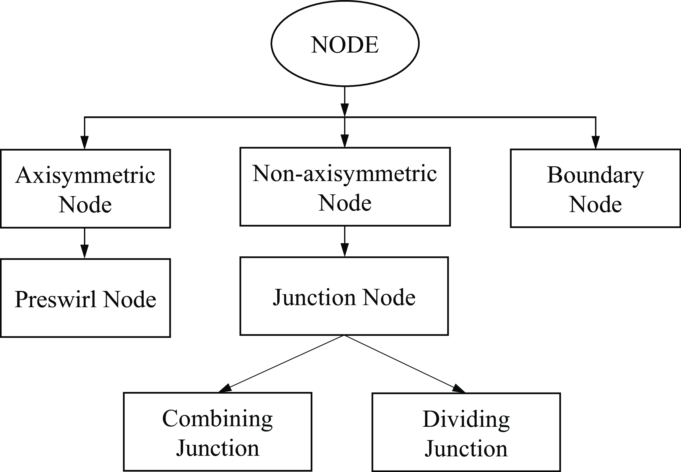
The concept of node originated from the lumped system analysis. The data structure of node element is defined as an abstract entity that represents flow cavities having a finite volume. The physical location of a node is at the barycentre of the represented cavity. A node is considered to represent the fluid properties in cavities in well-mixed condition [Reference Kulkarni and di Mare31, Reference Kulkarni and di Mare32], hence termed as the lumped-volume model. While this assumption is valid for small cavities, the gas states might vary significantly in large cavities. The node data structure is subdivided into several types. Figure 7 shows the taxonomy of node data structure in the present flow network modeller. It might be observed that this taxonomy structure allows instancing of specific types of nodes to represent specific types of flow cavities.
Taxonomy of node data structure.

As shown in Fig. 7, an axisymmetric node can be instanced to represent an axisymmetric cavity in flow network model. This type of node incorporates free vortex model to simulate the vortical flows in cavities. It can compute the losses generated by flow windage and due to the features protruding in cavity. The pre-swirl node is a sub-type of axisymmetric node and is specially developed to represent the turbine disc pre-swirl cavity [Reference Brillert, Reichert and Simon40]. The pre-swirl node has intrinsic methods to identify the links representing pre-swirl nozzles [Reference Benra, Dohmen and Schneider41] and turbine blade-root entry holes and to compute the pre-swirl flow losses.
A non-axisymmetric node is developed to represent the non-axisymmetric cavities in engine, wherein the tangential component of velocity is supressed. Junction node inherits the attributes of non-axisymmetric node data structure. It can compute both combining and dividing flow losses depending on the flow direction. Boundary nodes are generated at the boundaries of flow network model. All these nodes acquire their global number from the connectivity table.
The automated pre-processing methodology [Reference Kulkarni17, Reference Kulkarni and di Mare31, Reference Kulkarni and di Mare32] of node data structure calculates various internal parameters for axisymmetric node elements such as, the coordinates of cavity barycentre, number of solid walls, number of speed-frames and the description of protruding bolts etc. It examines the node cavity polygon to find the segments created from aerodynamic boundaries. These segments are interrogated to obtain the global number, headings, locations and pointers to the links connected to that node. The junction type node has specialised pre-processing methods to acquire their types [Reference Kulkarni and di Mare31, Reference Kulkarni and di Mare32] from the engine geometry model such as, a T-junction node, a Y-junction node, a valve node, a sudden or gradual expansion and contraction type node etc. By identifying the type of junction node, a representative flow loss model is explicitly allocated to that specific node instance. The boundary node data structure incorporates special database enquiry methods, which are designed to fetch and apply the flow boundary conditions to the network model.
2.2 Link element
Link is an abstract data structure that represents the flow paths connecting nodes of a flow network model. These flow-paths can include a variety of air system components and, therefore, the link data structure and its subtypes are primarily designed to contain the description of 1D flow loss models [Reference Kulkarni and di Mare31, Reference Kulkarni and di Mare32]. Flow paths are considered to have negligible volume and hence the time rate change of flow quantities across a link is very small.
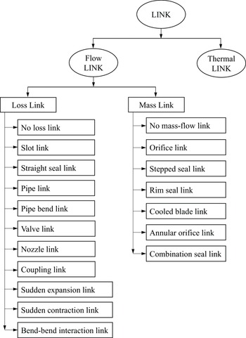
Figure 8 depicts the taxonomy of link data structure. The link data structure is categorised into flow links and thermal links, although this paper describes only the flow links. The flow link data structure is further divided into two major subtypes, termed as the loss links and the mass links. Their data structures inherit all properties, data members and methods of the flow link data structure. The mass-type links calculate the mass flow rate passing through a flow link; whereas loss-type links estimate the total pressure drop across a link. For example, a mass-type orifice link computes the mass flow rate based on an implicit measure of loss such as the coefficient of discharge, Cd, whereas the loss-type links such as labyrinth seals, pipes, junctions etc. explicitly calculate the total pressure loss across their loss stations and thereby obtain the mass flow rate passing through those links. Together these link elements can represent essentially all kinds of SAS components in a gas turbine engine.
Taxonomy of the library of link data structure.

The link elements are instanced by link-set data structure during the automated flow network model generation process. Its automated pre-processing method supplies various input variables to the link data structures [Reference Kulkarni17, Reference Kulkarni and di Mare31, Reference Kulkarni and di Mare32]. The individual pre-processing methods of flow links then fetch the geometric and non-geometric metadata from the geometry modeller and initialise various internal flow variables used by the flow loss models. During the flow computations, various link-loss elements exchange the information with the flow network solver through a common interface mechanism. The design of this interface mechanism ensures the consistency and the ease of adding more loss elements into the loss model library of Virtual Gas Turbines design-simulation environment.
2.3 Link-set element
Link-set is a container-type data structure that is designed to represent both short and long flow paths [Reference Kulkarni and di Mare31, Reference Kulkarni and di Mare32]. A short flow path contains only one flow link representing an air system component such as an orifice or a seal etc., whereas a long flow-path such as a long pipe usually includes multiple SAS components such as, bends, valves, manifolds, sudden or gradual contractions and expanders and internal constrictions etc. The link-set data structure assembles all links in a flow-path that are connected in series, registers the nature of each link, maintains the sequence of those links, associates a loss model to each link and supplies the boundary conditions to each link element, thereby generating a unified flow-path description.
The link-set data structure holds various important variables. It gets the global number of connected nodes, the number of links contained in it and the number of link-set repetitions along circumferential direction. The detailed process of link-set assembly is explained in Refs. [Reference Kulkarni and di Mare31, Reference Kulkarni and di Mare32]. Such a loss-link assembly generates a system of tightly coupled simultaneous linear equations for each flow path. The link-set instances the appropriate type and number of link data structures during the pre-processing phase and maintains the pointers to flow links and adjacent nodes. Link-set then communicates with each contained loss link and starts loading the relevant data in them.
The link-set data structure establishes connectivity in the flow network model by virtue of its association properties. It provides a common interface to all types of link elements; thereby facilitating the information exchange between the flow network solver and the link elements. The pre- and post-processing methods of link-set data structure include data enquiry methods, and thus, the flow network modeller can fetch and return the geometry parameters and the boundary conditions parameters to other application spaces of Virtual Gas Turbines design-simulation environment.
The link-set data structure also has certain limitations. For example, it cannot include both mass-type links and loss-type links in the same link-set. The pre-processing method of link-set data structure ensures that these flow link types cannot be assembled as they employ different entropy generation mechanisms, which prevents the generation of the tightly coupled system of equations in flow network solver.
2.4 Solver connectivity
The present flow network solver has been designed to operate with any kind of node connectivity pattern. The connectivity in the flow network modeller is maintained by both node and link-set data structures. The node data structure establishes the connectivity with link-sets by recording the number of link-set connections and the identity of each link-set. Similarly, the link-set data structure records the global numbers of adjacent nodes. Both node and link-set data structures retain the pointers to the connected entities; thus, allowing the communication of their internal variables through shared methods.
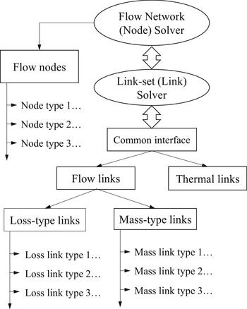
Figure 9 shows the hierarchical twin-layered arrangement of the present flow network solver. The flow network solver iterates on the node elements to compute the state of the gas in the SAS cavities, and it communicates with the link-set solver to obtain the state of fluxes across the link-sets. The link-set solver collects loss variables from different types of loss link elements and solves gas dynamic equations for each flow path. It then returns the state of fluxes at each node–link-set interface to the flow network solver.
Hierarchical structure of network (node) and link-set (loss links) solvers.

2.5 Application of boundary conditions
The application of flow boundary conditions is one of the most tedious tasks in SAS flow network modelling. In the present flow network modeller, the boundary node data structure is furnished with an automated pre-processing method. The boundary nodes send enquiries to the engine performance model along with their headings and location coordinates in the SAS flow network model. The associative object-oriented framework of Virtual Gas Turbines design-simulation environment provides monitored channels for such information exchange between its application spaces or devices. After confirming the matching of both heading and the location coordinates, the engine performance model returns the performance data to the flow network model for each operation point of interest.
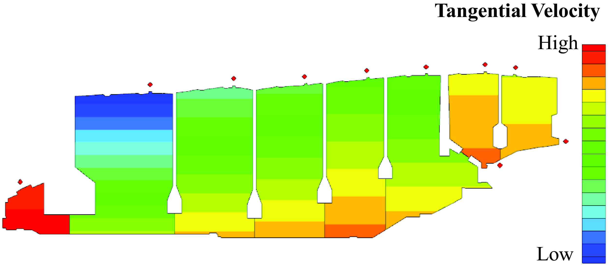
Similarly, the application of rotational speed boundary conditions to SAS flow network model is another labourious, error-prone and non-value-added activity. In the present flow network modeller, the cavity node data structure holds an automated pre-processing method that enquires, fetches and applies the rotational speed boundary conditions to the cavity walls. Each node sends a data request to the feature dynasty-based geometry model [Reference Kulkarni17, Reference Kulkarni, Lu, Wang and di Mare28, Reference Kulkarni, Lu, Wang and di Mare29] of the gas turbine engine. The geometry modeller acquires the rotational speed from the speed-dynasty or the ancestor spool feature and returns it to the node pre-processor. The node pre-processor then calculates the average tangential velocity of each cavity wall.
Figure 10 displays the flow network model of the secondary air system of a three-spool gas turbine engine. The automated process of generating such a whole-engine flow network model requires minimal computing resources compared to that required for generating a full-scale CFD model. If the engine geometry model already exists, it takes only a few minutes to transform the features, to fetch and apply the flow and speed boundary conditions and to initiate the SAS analysis at multiple operating points. This comprehensive methodology significantly reduces the overall SAS design-analysis time-cost and the dependency on human expertise.
Generation of flow network model consisting of nodes (red) and flow links (green) [Reference Kulkarni17].

3.0 Mathematical formulation
3.1 The node solver
This section describes the mathematical formulation of the present 1D flow network solver, its flow variables, and its communication protocols. This flow network solver solves the conservation equations of mass flow rate (
 $\dot w$
), meridional momentum
 $\left( {{M_m}} \right)$
, tangential momentum
 $\left( {{M_\theta }} \right)$
and internal energy (e) to find the steady state solution for four primary flow variables namely, the meridional velocity (u
m
), tangential velocity (u
θ
), static temperature (T) and static pressure (P) at each node in the network. In its most basic form, the conservation equation for any node k can be written as shown in Equation (5),
 \begin{align}\frac{{\partial {\mathbb{q}^{t + 1}}}}{{\partial t}} = \; - \mathfrak{d}\dot \Re \end{align}
where,
 $\mathbb{q}$
is the vector of conservation quantities and
 $\mathfrak{d}\dot{\mathfrak{R}}$
is the vector of time rate change of derivatives of residuals of conservation quantities. The conservation quantities are related to the primary flow variables through the time rate change of residuals at interfaces of links, losses in cavities and volumetric forces within cavities. The fundamental nature of this mathematical scheme is to drive the residuals of conservation equations to zero [Reference Kulkarni17].
Apart from the primary flow variables, the solver also computes several secondary and auxiliary flow variables. A total of six secondary variables are evaluated, namely, the total temperature (T
0), total pressure (P
0), meridional sonic velocity (
 $u_m^{\ast}$
), tangential sonic velocity (
 $u_\theta ^{\ast}$
), static temperature at sonic condition (
 ${T^{\ast}}$
) and static pressure at sonic condition (
 ${P^{\ast}}$
). The auxiliary variables include fluid density (
 $\rho$
), entropy at static condition (s) and at total condition (s
0), enthalpy at static condition (h) and at total condition (
 ${h^0}$
) and the sonic velocity (a). These variables are arranged as shown in Equations (6)–(9),
 \begin{align}q{n^{prim}} = \;\left\{ {\begin{array}{c@{\quad}c@{\quad}c@{\quad}c}{{u_m}} & {{u_\theta }} & T & P\end{array}} \right\}\quad aux{n^{prim}} = \;\left\{ {\begin{array}{c@{\quad}c@{\quad}c@{\quad}c}\rho & h & s & a\end{array}} \right\}\end{align}
 \begin{align}q{n^{sonic}} = \;\left\{ {\begin{array}{c@{\quad}c@{\quad}c@{\quad}c}{u_m^*} & {u_\theta ^*} & {{T^*}} & {{P^*}}\end{array}} \right\}\quad aux{n^{sonic}} = \;\left\{ {\begin{array}{c@{\quad}c@{\quad}c@{\quad}c}{{\rho ^*}}& {{h^*}}& {{s^*}}& a\end{array}} \right\}\end{align}
 \begin{align}qn{0^{sec}} = \;\left\{ {\begin{array}{c@{\quad}c@{\quad}c@{\quad}c} 0& 0& {{T^0}}& {{P^0}}\end{array}} \right\}\quad auxn{0^{sec}} = \left\{ {\begin{array}{c@{\quad}c@{\quad}c@{\quad}c}{{\rho ^0}}& {{h^0}}& {{s^0}}& {{a^0}}\end{array}} \right\}\end{align}
 \begin{align}qn = \;\left\{ {\begin{array}{c@{\quad}c@{\quad}c@{\quad}c}w & {{M_m}}& {{M_\theta }}& e\end{array}} \right\}\quad \mathfrak{d}\dot \Re = \;\left\{ {\begin{array}{c@{\quad}c@{\quad}c@{\quad}c}{\dot w} & F& {{T_q}}& {\dot e}\end{array}} \right\}\end{align}
The variable tags ‘q’ and ‘aux’ indicate primary and auxiliary quantities, respectively, whereas ‘n’ indicates node. This variable structuring methodology is useful for linking the flow network solver with the Virtual Gas Turbines gas dynamic library [Reference di Mare42, Reference di Mare43]. This library consists of several hodograph transformations, and these are extensively used in the current formulation [Reference Kulkarni17, Reference Shapiro44, Reference Ames45]. Moreover, this solver incorporates several functions and methods for receiving the constructed datasets from plugins [Reference Kulkarni and di Mare31, Reference Kulkarni and di Mare32], for instancing and initialising the derived datasets, for visualising the network model [Reference Kulkarni and di Mare31, Reference Kulkarni and di Mare32], for evaluating the gas dynamic equations and for the post-processing of results etc.
At node k,
 $\mathfrak{d}\dot \Re $
can be expanded as shown in Equation (10). It is a vector of summation of all mass flow rates, the fluid forces at link-set openings, the torques applied by or on flow and the rate of change of flow energy at node k.
 \begin{align} \mathfrak{d}\dot{\mathfrak{R}}_{k}={\ \mathfrak{d}\left[ \begin{array}{c}\dot{w} \\F \\T_q \\\dot{e} \end{array}\right]}_k\ =\ {\mathfrak{d}\left[ \begin{array}{c}\rho Au_m \\\rho Au^2_m+\ PA \\\rho Au_{\theta }r \\\rho Au_mh \end{array}\right]}_k \end{align}
The time rate change of all residuals at k
th node are obtained using existing instantaneous values of primary flow variables at adjacent nodes and links.
 $\mathfrak{d}\dot{\mathfrak{R}}_{k}$
could be expressed as shown in Equation (11), where the residuals of conservation quantities are partially differentiated with respect to time t.
 \begin{align}\frac{\partial }{{\partial t}}{\left[ {\begin{array}{c}{\rho V}\\{\rho V{u_m}}\\{\rho V{u_\theta }r}\\{\rho Ve}\end{array}} \right]_k} = \;\frac{\partial }{{\partial t}}\left( {\mathfrak{d}\Re _k^{cavity} + \;\mathop \sum \limits_{n = 1}^{n = nlinks} \mathfrak{d}\Re _k^{links} + \;\mathfrak{d}\Re _k^{loss}} \right)\end{align}
The term at RHS,
 $\sum \mathfrak{d}\Re _k^{links}$
, represents the summation of residuals of conservation quantities at the interfaces of node k and flow links that connect to it. The term
 $\mathfrak{d}\Re _k^{cavity}$
represents the residuals of volumetric forces applied by walls of cavity and
 $\mathfrak{d}\Re _k^{loss}$
represents the residuals of conservation quantities generated due to flow losses in the cavity node k. These vector notations may be further expanded as shown in Equation (12) [Reference LeVeque46],
 \begin{align} \frac{\partial }{\partial t}{\left[ \begin{array}{c}\rho V \\\rho Vu_m \\\rho Vu_{\theta }r \\\rho Ve \end{array}\right]}_k=\ \frac{\partial }{\partial t}\left\{\ \ \ \ \ {\left[ \begin{array}{c}\dot{w} \\F \\T_q \\\dot{e} \end{array}\right]}^{cavity}_k+\ \sum^{n=nlinks}_{n=1}{{\left[ \begin{array}{c}\dot{w} \\F \\T_q \\\dot{e} \end{array}\right]}^{links}_k}+\ {\left[ \begin{array}{c}\dot{w} \\F \\T_q \\\dot{e} \end{array}\right]}^{loss}_k\right\} \end{align}
Flow links have negligible volume compared to that of nodes and thus flow perturbations can transmit through them instantaneously. Consequently, the residuals computed at the interfaces of links are always instantaneous in nature. If each of these quantities is identified separately owing to its origin, Equation (12) might be stated in a more compact and generic form as shown in Equation (13),
 \begin{align}\frac{{\partial {\mathbb{q}^{t + 1}}}}{{\partial t}} = {\left( {A + B + L} \right)^t}\end{align}
where, A represents the vector of time rate change of conservation quantities at the interfaces of connecting links, B represents the vector of time rate change of volumetric quantities in the node and L represents the vector of time rate change of conservation quantities due to the losses in cavity. In finite difference form, the conservation equation at a node can be expressed as shown in Equation (14),
 \begin{align}\frac{{{\mathbb{q}^{t + 1}} - {\mathbb{q}^t}}}{{\Delta \tau }} = {\left( {A + B + L} \right)^{t + 1}}\end{align}
For obtaining the steady state solution, conservation quantities should not vary with time and hence RHS must diminish to zero. This means that the sum of all residuals
 ${\left( {A + B + L} \right)^{t + 1}}\; \cong 0$
. The aforementioned formulation thus represents a well-configured system of simultaneous equations. As the volumes of all cavities remain constant, Equation (14) could be written as,
 \begin{align}\frac{{V\!\left( {{\mathbb{q}^{t + 1}} - \;{\mathbb{q}^t}} \right)}}{{\Delta \tau }} = -\mathfrak{d}\Re \end{align}
Equation (15) can be conveniently represented as shown in Equation (16), where
 ${\mathbb{q}^{t + 1}}$
represents the solution of Equation (15) based on the geometry parameters of node k and the residuals of conservation quantities.
 \begin{align}{\mathbb{q}^{t + 1}} = \; - \frac{{\sigma \Delta \tau }}{V}{\textrm{ }}\mathfrak{d}\Re \end{align}
The term
 $\frac{{\sigma \;\Delta \tau }}{V}$
is used for scaling the residuals of conservation quantities at node k having volume V. This factor also converts time rate change of conserved quantities into actual conservation quantities such as fluid mass, meridional momentum, tangential momentum and internal energy of fluid.
 $\sigma $
is Courant number for flow network model, which scales the speed of information propagation within the cavity of node k.
 $\Delta$
τ is the time required to form homogeneous flow mixture in cavity. This time period is important to fulfil the assumption that conservation quantities computed at the barycentre of cavity represent the fully mixed flow conditions. This residence time is not known a priory, and it needs to be computed considering the volume of each cavity and the total time steps required to achieve steady state in complete network. The residence time would be shorter for the nodes having smaller volumes, whereas it is longer for the nodes having larger volumes. The solver always uses the shortest possible time step for time marching to ensure that the link perturbations are not transmitted through a node before the end of time step.
The nonlinear unsteady flow equation, shown in Equation (16), states the conservation of flow quantities in node k. In order to obtain the change in primary flow variables, the Equation (16) is converted into locally linear simultaneous algebraic equation as shown in Equation (17). The transformation Jacobian [Reference Laney47] has been defined as,
 \begin{align}\left[ {\partial {\mathbb{q}^{t + 1}}} \right]\left[ {\mathfrak{d}\mathfrak{q}} \right] = -\mathfrak{d}{\mathbb{q}^t} = - \frac{{\sigma \;\Delta \tau }}{V}\mathfrak{d}\Re \end{align}
The terms at LHS are Jacobian matrix of partial derivatives of conservation quantities
 $\left[ {\partial {\mathbb{q}^{t + 1}}} \right]$
with respect to primary flow variables and the vector of incremental change in primary flow variables
 $\left[ {\mathfrak{d}\mathfrak{q}} \right]$
, respectively. RHS represents residuals of conservation quantities, expressed by symbol
 $ -\mathfrak{d}{\mathbb{q}^t}$
and computed by term
 $ - \dfrac{{\sigma \;q\tau }}{V}\mathfrak{d}\Re $
. This equation represents the system of simultaneous equations as shown in Equation (18),
 \begin{align}\mathfrak{A}{\textrm{ }}\mathfrak{d}\mathfrak{q} = - \frac{{\sigma \;\Delta \tau }}{V}\mathfrak{d}\Re \end{align}
where,
 $\mathfrak{A}$
is the Jacobian matrix comprising local slopes (partial derivatives) of conservation quantities with respect to the primary flow variables.
 $\mathfrak{d}\mathfrak{q}$
is the vector comprising differential changes in the primary flow variables. The flow mixing time scale,
 $\Delta \tau $
, in Equation (18) is calculated based on the maximum speed of information propagation through nodes. The speed of information propagation is the highest possible magnitude of velocity in the direction of flow in links. For simplicity, the highest eigenvalue of the system of simultaneous equations for connecting link-sets is chosen, which is also known as spectral radius,
 ${\mathfrak{S}^R}$
. In the present flow network solver, the spectral radius is calculated as
 $A\;\left| {{u_m} + \;a} \right|$
, where A is area of opening of a link-set into cavity,
 ${u_m}$
is the highest flow velocity in connecting link-set and
 $a$
is speed of sound at existing static temperature in that link-set. This system of equations is represented by the conventional notation shown in Equation (19),
 \begin{align}\mathfrak{A}{\textrm{ }}\mathfrak{d}\mathfrak{q} = -\mathfrak{d}\Re \end{align}
And thus,
 \begin{align}\mathfrak{d}\mathfrak{q} = -\!\mathfrak{A}{{\textrm{ }}^{ - 1}}\mathfrak{d}\Re \end{align}
For obtaining the solution of system of simultaneous equations, it is necessary to invert Jacobian matrix
 $\mathfrak{A}$
assuming that it is not singular and its inverse does exist. Equation (21) can be obtained after substituting the terms in Jacobian matrix
 $\mathfrak{A}$
and the vector
 $\mathfrak{d}\mathfrak{q}$
,
 \begin{align}\left[ {\begin{array}{c@{\quad}c@{\quad}c@{\quad}c}{\dfrac{{\partial w}}{{\partial {u_m}}}} & {\dfrac{{\partial w}}{{\partial {u_\theta }}}} & {\dfrac{{\partial w}}{{\partial T}}} & {\dfrac{{\partial w}}{{\partial P}}}\\[9pt] {\dfrac{{\partial {M_m}}}{{\partial {u_m}}}} & {\dfrac{{\partial {M_m}}}{{\partial {u_\theta }}}} & {\dfrac{{\partial {M_m}}}{{\partial T}}} & {\dfrac{{\partial {M_m}}}{{\partial P}}}\\[9pt] {\dfrac{{\partial {M_\theta }}}{{\partial {u_m}}}} & {\dfrac{{\partial {M_\theta }}}{{\partial {u_\theta }}}} & {\dfrac{{\partial {M_\theta }}}{{\partial T}}} & {\dfrac{{\partial {M_\theta }}}{{\partial P}}}\\[9pt] {\dfrac{{\partial e}}{{\partial {u_m}}}} & {\dfrac{{\partial e}}{{\partial {u_\theta }}}} & {\dfrac{{\partial e}}{{\partial T}}}& {\dfrac{{\partial e}}{{\partial P}}}\end{array}} \right]\;\;\;\;{\left[ {\begin{array}{c}{\begin{array}{c}{\mathfrak{d}{u_m}}\\[5pt] {\mathfrak{d}{u_\theta }}\\[5pt] {\mathfrak{d}T}\\[5pt] \end{array}}\\[5pt] {\mathfrak{d}P}\end{array}} \right]_k} = \; - \left[ {\begin{array}{c}{\mathfrak{d}w\;}\\[5pt] {\mathfrak{d}{M_m}}\\[5pt] {\mathfrak{d}{M_\theta }}\\[5pt] {\mathfrak{d}e}\end{array}} \right]_k^\Re \end{align}
The
 $\mathfrak{A}$
matrix can be represented as shown in Equation (22) by substituting the flux variables for conservation variables [Reference LeVeque46]. It is possible to write the exact analytical forms of partial derivatives of flux variables, which simplify the computations of partial derivatives and hence the actual matrix inversion is not necessary. This reduces the number of computations substantially.
 \begin{align}\frac{V}{\tau }\;\left[ {\begin{array}{c@{\quad}c@{\quad}c@{\quad}c}{\dfrac{{\partial \rho }}{{\partial {u_m}}}}& {\dfrac{{\partial \rho }}{{\partial {u_\theta }}}}& {\dfrac{{\partial \rho }}{{\partial T}}}& {\dfrac{{\partial \rho }}{{\partial P}}}\\[9pt] {\dfrac{{\partial\!\left( {\rho {u_m}} \right)}}{{\partial {u_m}}}} & {\dfrac{{\partial\!\left( {\rho {u_m}} \right)}}{{\partial {u_\theta }}}} & {\dfrac{{\partial\!\left( {\rho {u_m}} \right)}}{{\partial T}}} & {\dfrac{{\partial\!\left( {\rho {u_m}} \right)}}{{\partial P}}}\\[9pt] {\dfrac{{\partial\!\left( {\rho {u_\theta }r} \right)}}{{\partial {u_m}}}} & {\dfrac{{\partial\!\left( {\rho {u_\theta }r} \right)}}{{\partial {u_\theta }}}} & {\dfrac{{\partial\!\left( {\rho {u_\theta }r} \right)}}{{\partial T}}} & {\dfrac{{\partial\!\left( {\rho {u_\theta }r} \right)}}{{\partial P}}}\\[9pt] {\dfrac{{\partial\!\left( {\rho e} \right)}}{{\partial {u_m}}}} & {\dfrac{{\partial\!\left( {\rho e} \right)}}{{\partial {u_\theta }}}} & {\dfrac{{\partial\!\left( {\rho e} \right)}}{{\partial T}}} & {\dfrac{{\partial\!\left( {\rho e} \right)}}{{\partial P}}}\end{array}} \right]{\left[ {\begin{array}{c}{\begin{array}{c}{\mathfrak{d}{u_m}}\\[5pt] {\mathfrak{d}{u_\theta }}\\[5pt] {\mathfrak{d}T} \end{array}}\\[5pt] {\mathfrak{d}P}\end{array}} \right]_k} = - \dfrac{V}{\tau }\left[ {\begin{array}{c}{\mathfrak{d}\!\left( \rho \right)\;}\\[5pt] {\mathfrak{d}\!\left( {\rho {u_m}} \right)}\\[5pt] {\mathfrak{d}\!\left( {\rho {u_\theta }r} \right)}\\[5pt] {\mathfrak{d}\!\left( {\rho e} \right)}\end{array}} \right]_k^\Re \end{align}
After inverting Jacobian matrix and multiplying it by RHS, a vector containing differential change in primary flow variables is obtained. This vector is used to update the values of primary and auxiliary flow variables at node k as shown in Equations (23)–(26),
 \begin{align}u_m^{t + 1} = u_m^t + \mathfrak{d}{u_m}\qquad {\rho ^{t + 1}} = {\rho ^t} + \mathfrak{d}\rho \end{align}
 \begin{align}u_\theta ^{t + 1} = u_\theta ^t + \mathfrak{d}{u_\theta }\qquad {h^{t + 1}} = {h^t} + \mathfrak{d}h\end{align}
 \begin{align}{T^{t + 1}} = {T^t} + \mathfrak{d}T\qquad {s^{t + 1}} = {s^t} + \mathfrak{d}s\end{align}
 \begin{align}{P^{t + 1}} = {P^t} + \mathfrak{d}P\qquad {a^{t + 1}} = {a^t} + \mathfrak{d}a\end{align}
These new values of flow variables at each node are used as instantaneous guess values in the next iteration of solver. The network solver continues iterations to compute the conservation quantities at the nodes until a convergence criterion is satisfied.
3.2 Solver interfaces
The RHS terms in Equation (12) represent the summation of residuals of conservation quantities within the node k and at the interfaces of node k and flow links that connect to it. The flow network solver obtains the residual vectors
 $\mathfrak{d}\Re _k^{cavity}$
and
 $\mathfrak{d}\Re _k^{loss}$
from the representative loss model of cavity node k. Depending on the type of the node such as, axisymmetric node, non-axisymmetric node, junction node etc., the specific loss model for node k generates these residual vectors and returns those to the flow network solver.
Further, the flow network solver obtains the RHS term
 $\sum \mathfrak{d}\Re _k^{links}$
from each link-set connected to node k. It supplies the global node numbers and flow boundary variables to a link-set j. The link-set j acquires the partial derivatives of flux and loss variables from the loss models of each contained flow links. It also provides the spectral radius,
 ${\mathfrak{S}^R}$
, of its Jacobian matrix to calculate the flow residence time in node k. These variables are substituted in Equation (12). More explanation is provided in Section 3.3.
3.3 The link-set solver
The fundamental mathematical scheme of link-set solver is similar to that of flow network solver. It uses linearised gas dynamic equations, which are coupled to the linearised loss correlations in flow loss models. These loss models represent the flow physics in air system components.
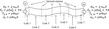
The conservation variables computed by link-set solver.

Figure 11 shows the schematic representation of link-set j connecting nodes k and m. The flow variables at the interfaces of connected nodes, k and m, are used as the boundary conditions. The link-set j can have multiple internal stations that are physically spaced in meridional plane. The number and the locations of internal stations are determined during the pre-processing stage of the link-set [Reference Kulkarni and di Mare31, Reference Kulkarni and di Mare32]. The link-set solver computes four primary variables namely, the meridional velocity
 $\left( {{u_m}} \right)$
, tangential velocity
 $\left( {{u_\theta }} \right)$
, static temperature (T) and static pressure (P). It also consists of two secondary variables and four sonic state variables, which are total temperature
 $\left( {{T^0}} \right)$
, total pressure
 $\left( {{P^0}} \right)$
, meridional sonic velocity
 $\left( {u_m^*} \right)$
, tangential sonic velocity
 $\left( {u_\theta ^*} \right)$
, enthalpy at sonic condition
 $\left( {{h^*}} \right)$
and entropy at sonic condition
 $\left( {{s^*}} \right)$
, respectively. Apart from these, auxiliary variables are also included in link-set solver namely, fluid density
 $\left( \rho \right)$
, enthalpy (h), entropy (s) and speed of sound (a). The auxiliary variables are also computed at total and sonic state conditions. All these flow variables are coupled through gas dynamic equations and geometry variables of link-set such as cross-section area (A). The link-set solver computes the mass flow rate
 $\left( {\dot w} \right)$
through all links in link-set j based on total pressure loss
 $\left( {{P^{0,\;\;loss}}} \right)$
between consecutive loss stations. These variables are arranged as shown in Equations (27)–(29),
 \begin{align}q{l^{\,primary}} = \;\left\{ {\begin{array}{c@{\quad}c@{\quad}c@{\quad}c}{{u_m}} & {{u_\theta }}& T & P\end{array}} \right\}\qquad aux{l^{primary}} = \;\left\{ {\begin{array}{c@{\quad}c@{\quad}c@{\quad}c}\rho & h & s & a\end{array}} \right\}\end{align}
 \begin{align}q{l^0} = \;\left\{ {\begin{array}{c@{\quad}c@{\quad}c@{\quad}c}0 & 0& {{T^0}}& {{P^0}}\end{array}} \right\}\qquad aux{l^0} = \left\{ {\begin{array}{c@{\quad}c@{\quad}c@{\quad}c}{{\rho ^0}}& {{h^0}}& {{s^0}}& {{a^0}}\end{array}} \right\}\end{align}
 \begin{align}q{l^{sonic}} = \;\left\{ {\begin{array}{c@{\quad}c@{\quad}c@{\quad}c}{u_m^*}& {u_\theta ^*}& {{T^*}}& {{P^*}}\end{array}} \right\}\qquad aux{l^{\,sonic}} = \left\{ {\begin{array}{c@{\quad}c@{\quad}c@{\quad}c}{{\rho ^*}}& {{h^*}}& {{s^*}}& a\end{array}} \right\}\end{align}
The names ‘q’ and ‘aux’ indicate arrays of primary and auxiliary variables, respectively, whereas ‘l’ indicates link or link-set. Such a variable arrangement has been useful to establish a common interface between the link-set solver and the loss model library of Virtual Gas Turbines design-simulation environment [Reference Kulkarni and di Mare48, Reference Kulkarni and di Mare49].
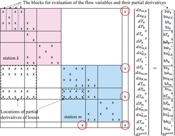
Equation (30) shows the expanded view of the system of simultaneous linear algebraic equations for station k of the link-set j. The LHS of Equation (30) includes a Jacobian matrix containing the partial derivatives of conservation quantities with respect to primary, total and sonic flow variables and a vector representing incremental changes
 $\left\{ {\Delta {\textrm{X}}} \right\}$
in primary flow variables at station k. It might be observed that the link-set Jacobian matrix is relatively sparse, and it is not symmetric about its diagonal. Some of the loss models generate partial derivatives of conservation quantities with respect to geometry variables. These partial derivatives occupy several diverse locations in the link-set Jacobian matrix. During the matrix assembly, each conservation equation is partially differentiated with respect to a flow variable. This process is repeated for all four primary, two total and four sonic state flow variables.

The RHS of Equation (30) consists of a vector representing the residuals of primary, total and sonic state flow variables. Equation (31) shows the generalised form of residual vector at station k.
 \begin{align}{\left[ {\begin{array}{c}{\mathfrak{d}\dot w}\\[5pt] {\mathfrak{d}{u_\theta }}\\[5pt] {\mathfrak{d}h}\\[5pt] {\mathfrak{d}s}\\[5pt] {\mathfrak{d}{T^0}}\\[5pt] {\mathfrak{d}{P^0}}\\[5pt] {\mathfrak{d}u_m^*}\\[5pt] {\mathfrak{d}u_\theta ^*}\\[5pt] {\mathfrak{d}{h^*}}\\[5pt] {\mathfrak{d}{s^*}}\end{array}} \right]_k} = {\left[ {\begin{array}{c}{{{\left( {\rho \;{u_m}A} \right)}_k}\; - \;{{\left( {\rho \;{u_m}A} \right)}_m} + \;\Delta \dot w}\\[5pt] {{{\left( {{u_\theta }} \right)}_k} - \;{{\left( {{u_\theta }} \right)}_m} + \;\Delta {u_\theta }}\\[5pt] {{{\left( h \right)}_k} - \;{{\left( h \right)}_m} + \;\Delta h}\\[5pt] {{{\left( s \right)}_k} - \;{{\left( s \right)}_m} + \;\Delta s}\\[5pt] {{{\left( {{T^0}} \right)}_k} - \;{{\left( {{T^0}} \right)}_m} + \;\Delta {T^0}}\\[5pt] {{{\left( {{P^0}} \right)}_k} - \;{{\left( {{P^0}} \right)}_m} + \;\Delta {P^0}}\\[5pt] {{{(u_m^*)}_k} - {{(u_m^*)}_m} + \Delta u_m^*}\\[5pt] {{{(u_\theta ^*)}_k} - {{(u_\theta ^*)}_m} + \Delta u_\theta ^*}\\[5pt] {{{\left( {{h^*}} \right)}_k} - \;{{\left( {{h^*}} \right)}_m} + \;\Delta {h^*}}\\[5pt] {{{\left( {{s^*}} \right)}_k} - \;{{\left( {{s^*}} \right)}_m} + \;\Delta {s^*}}\end{array}} \right]_k}\end{align}
Figure 12 shows the generalised assembly of the Jacobian matrix and the vector of residuals for link-set j having two stations, k and m. The loss model of the SAS component in link-set j provides the partial derivatives of its linearised loss correlations to the Jacobian matrix and the incremental variables to the vector of residuals. Both the Jacobian matrix and the vector of residuals are automatically assembled in block column-wise manner. The partial derivatives of loss correlations occupy various lower diagonal positions in the Jacobian matrix; thereby coupling the flow conditions at stations, k and m.
Assembly of the Jacobian matrix and the residual vector for link-set j.

Further the static pressure boundary conditions are applied by adding one equation and one unknown to the system of equations. The extra equation represents a mass continuity constraint, whereas the extra variable represents the exit pressure. The additional equations and unknowns appear in the Jacobian matrix as one extra row and column each, which are highlighted in Fig. 12.
To obtain the steady state solution for link-set j, the vector of residuals at the RHS (see Fig. 12) should diminish to zero. The link-set solver inverts the Jacobian matrix [Reference Golub and van Loan50] and multiplies it to the RHS using the standard routines of LAPACK library [51]. It solves the system of tightly coupled linearised simultaneous equations by balancing the mass flow rate, tangential velocity, total pressure and total temperature across the link-set j and then computes the residuals and the spectral radius of Jacobian matrix.
3.4 Interface with loss models
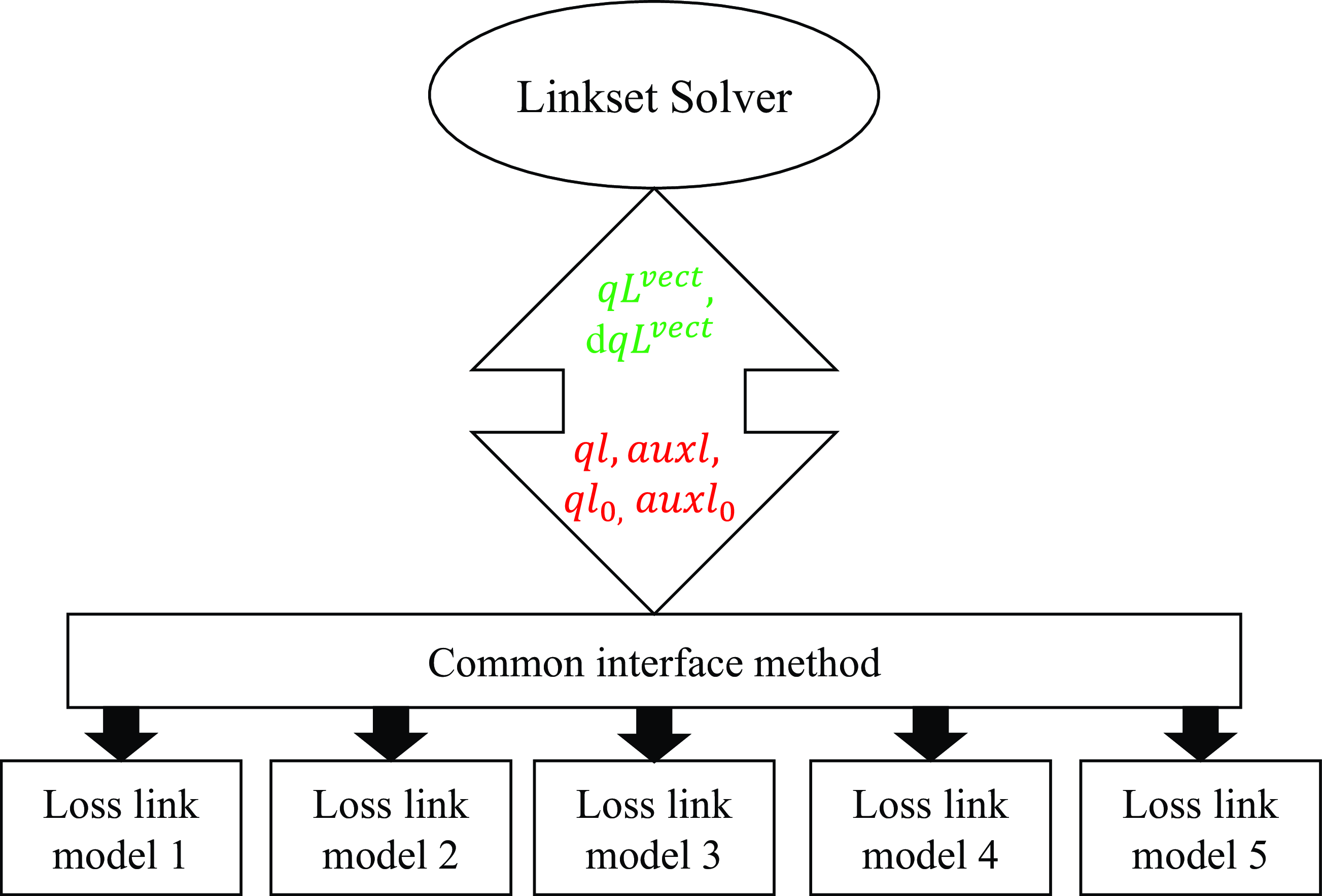
The link-set solver is coupled to the link data structures and they exchange data through a common interface irrespective of the type of the link. The solver provides the banded vectors of primary, total and auxiliary flow variables (see Equations (27)–(29)) to the link loss models. The link-set flow variables are associated through gas dynamic relations and hodograph transformations [Reference Kulkarni17, Reference di Mare42, Reference Ames45] and hence cannot be modified by the loss models. The loss models generate loss estimates using these flow variables and return the loss variables and their partial derivatives to the link-set solver through the loss vectors,
 $q{L^{vect}}$
and
 $dq{L^{vect}}$
. Figure 13 illustrates the variable exchange between link-set solver and loss models.
Interface between link-set solver and the SAS link loss models.

3.5 The SAS loss models
The present loss model library [Reference Kulkarni17] incorporates two forms of SAS loss models namely,
-
a) the loss-type links, which compute the mass flow rate based on inlet total pressure, exit static pressure and drop in total pressure (or rise in entropy)
-
b) the mass-type links that compute the rise in entropy (or drop in total pressure) based on inlet total pressure, exit static pressure and the mass flow rate through the link
The linearisation methods for both loss-type and mass-type loss models evaluate the partial derivatives of loss correlations with respect to flow and geometry parameters [Reference Kulkarni17, Reference Kulkarni and di Mare48, Reference Kulkarni and di Mare49] and generate four incremental loss variables, namely mass flow rate difference (
 $\Delta \dot w$
), total pressure drop (
 $\Delta {P^0}$
), total temperature rise (
 $\Delta {T^0}$
) and the difference in tangential velocity (
 $\Delta {u_\theta }$
). The vector of these loss quantities and the vector containing their partial derivatives are shown in Equation (32).
 \begin{align}q{L^{vect}} = \;\left[ {\begin{array}{c}{\Delta \dot w}\\{\Delta {P^0}}\\{\Delta {T^0}}\\{\Delta {u_\theta }}\end{array}} \right]\quad dq{L^{vect}} = \;\left[ {\begin{array}{c}{\mathfrak{d}\dot w}\\{\mathfrak{d}{P^0}}\\{\mathfrak{d}{T^0}}\\{\mathfrak{d}{u_\theta }}\end{array}} \right].\end{align}
Depending on the type of the loss model, either the total pressure drop or the mass flow rate can be predicted. Therefore, for a loss model that predicts total pressure drop, the mass flow rate through that link is considered as a free variable and vice-a-versa. This difference in predicting the loss variables based on loss-type approach and mass-type approach necessitates the loss vectors to be modified as shown in Equations (33) and (34).
For loss-type link-set:
 \begin{align}q{L^{vect}} = \;\left[ {\begin{array}{c}{freevar}\\{\Delta {P^0}}\\{\Delta {T^0}}\\{\Delta {u_\theta }}\end{array}} \right]\quad dq{L^{vect}} = \;\left[ {\begin{array}{c}{\mathfrak{d}freevar}\\{\mathfrak{d}{P^0}}\\{\mathfrak{d}{T^0}}\\{\mathfrak{d}{u_\theta }}\end{array}} \right].\end{align}
For mass-type link-set:
 \begin{align}q{L^{vect}} = \;\left[ {\begin{array}{c}{\Delta \dot w}\\{freevar}\\{\Delta {T^0}}\\{\Delta {u_\theta }}\end{array}} \right]\quad dq{L^{vect}} = \;\left[ {\begin{array}{c}\mathfrak{d}{\dot w}\\{\mathfrak{d}freevar}\\{\mathfrak{d}{T^0}}\\{\mathfrak{d}{u_\theta }}\end{array}} \right].\end{align}
The loss variables are returned to the RHS vector of Equation (31) through
 $q{L^{vect}}$
, whereas the partial derivatives of loss correlations are returned to the link-set Jacobian matrix through
 $dq{L^{vect}}$
.
3.6 Handling of flow reversal and flow choking
Flow reversal and flow choking are commonly observed in SAS flow network models. Flow reversal might occur either due to poor SAS design or due to numerical instability, whereas flow choking is intentionally used to meter and control the mass flow rates in specific regions of SAS. Various flow paths in the SAS are designed to choke during certain operating conditions. Therefore, the present network solver incorporates both the reversed flow and choked flow handling capabilities.
Due to the tightly coupled nature of equations in the present solver, it can handle simultaneous flow reversal conditions in multiple link-sets. While iterating, the link-set solver monitors pressure, temperature and meridional velocity at both source and sink nodes to estimate the possibility of flow reversal. If flow seems to be reversing, the link-set solver swaps the pointers to the source and sink nodes; thereby updating the link-set boundary conditions.
Flow choking can be detected, if meridional flow velocity at any station in a link-set equals the local sonic velocity. In the present link-set solver, local sonic conditions are computed at each internal station of link-set and thus flow choking can be easily detected. At present, the loss models in the library cannot predict flow losses at sonic or supersonic flow conditions; thus keeping the mass flow rate constant through a choked link-set.
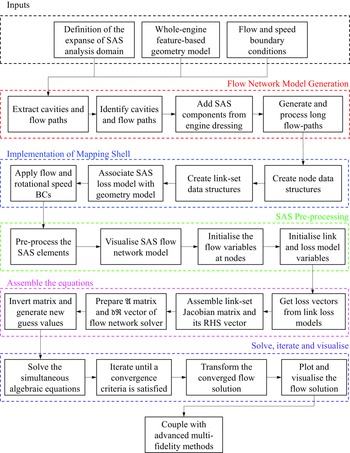
The overall workflow chart for SAS flow network analyses.

4.0 SAS workflow automation
The various in-built modules of computational geometry modeller and flow network modeller of Virtual Gas Turbines design-simulation environment are seamlessly interconnected to perform the automated whole-engine SAS flow network analysis. The major steps of this workflow are summarised below and illustrated in Fig. 14.
-
(1) After generating the engine geometry model, the flow network modeller is initiated to start the SAS analysis. User needs to provide a valid list of aerodynamic shapes to the flow network modeller to define the SAS analysis domain.
-
(2) Flow network modeller follows mechanised steps to create the flow network model. It scrutinises the computational geometry model of engine and extracts the cavities and flow paths. Node elements are created to represent the cavities and junctions, whereas link-set elements are created to represent the flow paths. The modeller establishes the connectivity between the nodes and the link-sets.
-
(3) The flow boundary conditions can either be provided through input file [Reference Kulkarni and di Mare31, Reference Kulkarni and di Mare32] or can be fetched from the chapter and verses data structure of engine performance model, although this method is not described here.
-
(4) Next, the flow network modeller automatically pre-processes the SAS elements such as nodes, link-sets and links and fills in the requisite data.
-
(5) After pre-processing the model, both the flow network solver and link-set solver variables are initialised. The flow network solver generates the guess values of nodal velocities, pressures and temperatures using a simple averaging method [Reference di Mare42], and these are supplied to the link-set solver to initialise its primary and auxiliary flow variables at each station of all link-sets.
-
(6) After flow initialisation:
-
i. The flow network solver initiates its Newton iterations (Section 3.1) and begins the preparation of its Jacobian matrix and the RHS vector,
$\mathfrak{d}\Re $
, for each node. Each node requests the connected link-sets to supply the vector of their residuals. -
ii. The link-set solver starts assembling link-set Jacobian matrix (Section 3.3) and the corresponding RHS vector for each link-set. Each link-set requests loss vectors to the loss model of each contained link.
-
iii. Each link loss model computes the flow losses and their partial derivatives and returns those to the link-set solver. The loss variables are added into the residual vector of link-set solver and their partial derivatives are assembled in the link-set Jacobian matrix.
-
iv. The link-set solver solves the system of tightly coupled linearised simultaneous equations and generates a vector of residuals of conservation quantities,
$\mathfrak{d}{\Re ^{links}}$
and the spectral radius,
${\mathfrak{S}^R}$
, and returns those to the flow network solver. This process is repeated for each link-set in a flow network model. -
v. The flow network solver further requests the residuals of conservation quantities due to the flow losses,
$\mathfrak{d}\Re _k^{loss}$
, and the volumetric forces,
$\mathfrak{d}\Re _k^{cavity}$
, in each node. -
vi. The flow network solver scales the residuals,
$\mathfrak{d}\Re $
, by the flow residence time and fully assembles its Jacobian matrix and the RHS vector. -
vii. The flow network solver inverts the Jacobian matrix and multiplies to the vector of residuals to generate the differential change in primary flow variables at each node, which are used to generate their new guess values. This completes a Newton iteration of the flow network solver.
-
viii. This process is repeated until the maximum variation of all primary flow variables at all nodes in a flow network model reduces below 1.e-10. The convergence of primary flow variables can be monitored as the computations progress.
-
-
(7) After attaining the steady state, the flow network modeller transforms the numerical data at nodes and link-sets in a format suitable for visualisation. The results of the flow network solver can be visualised in post-processing software, such as Gnuplot [Reference Janert52] and Tecplot [53] etc.


Apart from selecting the flow network domain, all the aforementioned operations are completely automated, and they do not require any human intervention; thus, demonstrating the level of automation achieved in the present work.
Flow network of the cavities in IPC rotor drum.

5.0 Results demonstration
Figure 15 shows a pre-processed flow network model of SAS cavities within the rotor drum of intermediate pressure compressor (IPC). These cavities are connected by short links such as orifices, annular orifices, seals and couplings. As shown in Fig. 15, various aerodynamic shapes representing these short links are used for generating the network model. The model consists of 18 nodes (8 cavity nodes and 10 boundary nodes) and a total of 17 link-sets. All link-sets in this model have only two stations. The boundary conditions shown in Table 1 are applied at the boundary nodes. The intermediate pressure compressor delivery air enters into the flow network model through the link-sets representing eighth-stage IPC disc bore and the air-to-air seal. This air exits through the link-sets representing holes on the IPC rotor drum and through the holes on the drive arm of first stage IPC disc. Figure 15 shows the expected direction of air flow in this simpler flow network model.
Flow boundary conditions for the IPC network cavities

The present flow network solver is executed to obtain steady flow solution in this network model. While performing the computations, the variations of pressure and temperature are monitored at all cavity nodes. Figure 16 shows the convergence plots of residuals of conservation quantities namely, the continuity, meridional momentum, tangential momentum and the internal energy. It can be observed that the flow solution is converged successfully in 2000 Newton iterations.
Convergence history of the conservation quantities at nodes.

Static pressure variation in IPC cavities.

Mass flow rate variation in connecting links.

Variation of static pressure (P s ) in IPC cavities.

Variation of static temperature (T s ) in IPC cavities.

Variation of meridional velocity (u m ) in IPC cavities.

Variation of tangential velocity (u θ) in IPC cavities.

Figures 17 and 18 show the variation of static pressure at each cavity node and the mass flow rate through each link-set plotted against the solver iterations. It is observed that the mass flow rate through each link-set is not monotonously increasing or decreasing; but it is varying with the pressure ratio across that link-set. Flow reversals are also observed in certain link-sets with the variation of static pressures in cavities. These results are converted into Tecplot [53] format by the out-plugin of the flow network modeller.
The final results of flow network computations are visualised in Tecplot. Figures 19–22 display the variation of static pressure, static temperature, meridional velocity and tangential velocity in the IPC cavities, respectively. The distribution of static pressure and temperature in the IPC cavities is in accordance with the flow boundary conditions and the predicted flow direction in various link-sets also matches the intended flow direction. Figure 20 shows the rise in nodal static temperatures due to cavity windage. Figure 21 shows small meridional velocity in all cavities; thus, confirming that the meridional momentum is almost negligible in large pressure chambers. Figure 22 displays the increase in flow tangential velocity as it passes through IPC cavities from IPC exit to inlet. Figure 22 also shows the radial variation of tangential velocity in IPC cavities, which is obtained by scaling the tangential velocity at cavity barycentre using free vortex law.
6.0 Discussion and conclusions
The design, modelling and analysis of the secondary air system of gas turbine engines are still largely human dependent and labourious tasks with high associated time-cost. The literature review shows that the earlier solver formulations were designed to work in isolation and lack the suitable interfaces to develop multi-fidelity design-analyses systems. The SAS design-analysis methodology presented here addresses these challenges and fully achieves the following objectives:
-
(1) Generation of an integral, automated and generic flow network modeller, which is directly coupled to the computational geometry model of an aero gas turbine engine.
-
(2) Full integration of the geometry modelling and SAS flow network modelling application spaces of Virtual Gas Turbines design-simulation environment.
-
(3) Development of a novel, twin-layered mathematical formulation of SAS solver that seamlessly integrates gas dynamic equations to the respective loss models of SAS components.
-
(4) Enhancement of the generic SAS flow network modelling capabilities and its system-level integration.
The automated design-analysis capabilities and mathematical robustness of the Virtual Gas Turbines SAS flow network modeller are demonstrated through the results of IP compressor rotor drum flow network model. We claim that, unlike prior methodologies, this SAS design-analysis methodology offers multiple benefits such as
-
Swift generation of the whole engine SAS flow network model without any human interference, which is one of the prime requirements for the industrial-scale design work. This capability is not available in the current open literature.
-
Conducting quick and reasonably accurate performance assessments at early design stages for selecting a SAS system and to fix the outlines of various surrounding components.
-
Seamless transfer of numerical data within the associative workspaces of Virtual Gas Turbines design-simulation environment; thereby integrating the SAS design-analysis workflow into multi-layered, multi-fidelity design processes.
-
Significant reduction in the dependency on human expertise, design lead time and the design time-cost, which is an attractive and complete solution for a real engine application.
We, therefore, assert that this paper presents a comprehensive solution to one of the current industrial SAS design-analysis challenges. Some of the major implications of implementing this method include
-
A major step towards the automation of SAS design work.
-
Improvement in the gas turbine SAS design timescales.
-
Coexistence with CFD simulations for optimising specialised components, for designing localised geometry features and for conducting multi-fidelity simulations etc.
-
Development of design standards for the gas turbine SAS systems.
The present flow network modelling methodology uses a combination of high-fidelity geometry and low-fidelity flow representation, so it is much faster than, but not as accurate as CFD methods. In future, it is recommended to improve the flow physics representation in flow network modelling method by training the bulk flow models using CFD-based data, as demonstrated in Refs. [Reference Kulkarni and di Mare48, Reference Kulkarni and di Mare49] to retain their computational speed advantage while gaining the CFD-equivalent accuracy.
Acknowledgments
The authors are grateful to Rolls-Royce plc and UK-EPSRC DHPA for funding this work and for granting permission to publish this work.