Introduction
In the past decade, innovative carbon-based composite materials have turned the researchers in the direction to satisfy the ever-growing requirements in the field of modern communication systems. There are several types of conductive materials, such as continuous carbon fiber composite, reinforced continuous carbon fiber, carbon nanotubes (CNTs), conductive polymer, graphene, etc. Out of that, graphene is a 2-D carbon-based hexagonal lattice atomic structure, zero band-gap material, and owing to its unique atomic pattern, it provides high electrical/thermal conductivity, good corrosion resistance, non-toxic, toughness, and flexibility to the material. So, graphene has emerged as a substitute for the metal to carbon-based material [Reference Geim and Novoselov1]. Other, carbon fiber materials are too expensive and conductive polymers, CNTs provide low conductivity and relatively high sheet resistance. Since graphene is the world's thinnest non-metallic material, it also has an extremely high surface area to volume ratio compared to copper, gold, and silver. This makes graphene a very promising material for its use in supercapacitors, batteries, and RF fields. Graphene may change the world from metal to non-metallic structures in the future. Whereas, the graphene films are a promising alternative for applications in the field of industrial and aerospace science where lightweight and flexibility are of prime concern [Reference Bunch2–Reference Scida, Haque, Treossi, Smerzi, Ravesi, Borini and Palermo4]. There are many deposition techniques to grow graphene on a specific substrate. Graphene deposition synthesis on SiO2 or in-situ Ni0.5Zn0.5Fe2O4 ferrite nanoparticle with grafted-graphene oxide hybrid scaffold for broadband microwave absorber material is clarified in [Reference Yadav, Ghosh, Das and Bhattacharyya5, Reference Bhattacharyya, Prakash, Roy, Singh, Bhattacharyya, Maiti, Bhattacharyya and Das6]. One can achieve mass productivity and uniformity of the material with that chemical vapour deposition (CVD) process. A recent development in graphene deposition has brought a lot of other possibilities for making nano to large-scale nonmetallic structures.
Researchers have proposed a reconfigurable antenna utilizing graphene for microwave systems with parasitic impacts of the DC predisposition circuit and the effect of including the electric field impact structure between the transmitting patch and the ground [Reference Álvarez, Cheung and Thompson7, Reference Kumar, Basu, Talukdar and Nandi8]. Graphene-flakes printed non-resonant planar elliptical dipole antenna designed with moderate conductivity of printed graphene flakes for wireless communication is proposed in [Reference Lamminen, Arapov, With, Haque, Sandberg, Friedrich and Ermolov9, Reference Leng, Huang, Chang, Chen, Abdalla and Hu10]. Toward the graphene-based flexible antenna for the microwave regime based on various dielectric substrates such as polyimide, textile tags are discussed by the researchers in [Reference Vashi and Upadhyaya11–Reference Yan, Soh and Vandenbosch13]. Carbon fiber composite or magnetic conductor is also an alternative material of the graphene for a wireless antenna despite the lower gain and conductivity of the material. The presence of OH− ions in the composite leads to poor conductivity due to oxidation [Reference De Assis and Bianchi14, Reference Reyes-Vera, Arias-Correa, Giraldo-Muno, Catano-Ochoa and Santa-Marin15]. To create the wideband or multi-band frequency effect for improving the performance of the antenna, many researchers have also proposed techniques such as fractal geometrical structure, series fed aperture coupled, L, U, or T-shaped slot, multiple parasitic patches, defected or truncated ground structure, and shorted parasitic element [Reference Xu, Xu, Liu, Li and Liu16–Reference Desai, Upadhyaya, Patel, Bhatt and Mankodi22]. The power divider array with defected ground structure is also used to improve the gain and bandwidth of the antenna [Reference Vahora and Pandya23]. The development of wide antennas is quite challenging to maintain their performance under the bent position as compared to ordinary single-band antennas[Reference Desai and Upadhyaya24–Reference Mohandoss, Palaniswamy and Thipparaju31].
In this paper, a wideband semi-flexible antenna is proposed using graphene as a conductive material with epoxy glass fiber (G-10) as a substrate. G-10 is a kind of composite material laminated with glass fiber and resin. It has the characteristics of insulation, corrosion resistance, and wear resistance. G-10 composite material is made from glass fiber cloth and epoxy resin, originally developed as aircraft material. The material can withstand great forces without damage and deformation and it will not be saturated with water vapor and liquid and has the characteristics of insulation, acid, and alkali resistance with better texture and performance than that of FR-4.
The proposed antenna is compared with the copper and alumina foil for performance analysis which is discussed in section “Proposed antenna design and fabrication”. Design and characterized system set up parameters with a parametric study is analyzed in section “Results and discussion”. Section “Bending analysis” includes simulated and fabricated results interpretation and discussion where bending analysis is also explained. Section “Conclusion” concludes the work.
Proposed antenna design and fabrication
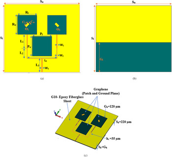
Designing wideband and robust smart devices antenna with acceptable efficiency and performance, especially when the antenna is expected to have lightweight, low-profile, and tailored characteristics, is desired. A linearly polarized wideband planar graphene-based antenna on the epoxy glass fiber substrate antenna is presented. Instead of the complex geometry of fractal antenna or co-planner waveguide techniques, this antenna is fabricated using a simple configuration of array and parasitic element effect as shown in Fig. 1.
Proposed antenna. (a) Top view. (b) Bottom view. (c) Perspective view.

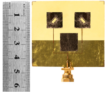
As shown in Fig. 2, the fabricated prototype is integrated using a G-10 substrate with a dielectric constant εr = 4.7 and loss tangent (tan δ) equal to 0.0012 with a thickness of 120 μm of the graphene sheet. Graphene sheet has a surface resistivity of 2.7 μΩ/m, the conductivity of 3.7 × 10⁵ S/m, and the density of 1.9 g/cm3, which is available from the datasheet of graphene sheet [32]. The laser technique is used to achieve higher precision in geometric dimensions with low-power cutting flame to protect the sheet being damaged. SMA connector is connected to fix the patch and ground with epoxy paste to dodge the graphene sheet from being affected by the soldering process. The design parameters of the proposed antenna are shown in Table 1.
Fabricated prototype of the graphene-based antenna.

Proposed antenna design parameters (all dimensions are in mm)

Figure 3 illustrates the evolution of antenna from 2 × 1 simple array to parasitic patch with defected ground structure and at the end with the addition of slots in the radiating patch. It can be observed that using the proposed design, the bandwidth of the antenna is significantly improved. The impedance bandwidth of all three antennas is shown in Table 2.
Antenna evolution from ANT-1, ANT-2, ANT-3, and ANT-4.

The proposed antenna design evolution of ANT-1 to 4.

To feed a 2 × 1 radiating patch, a power divider is used scientifically to achieve 50 Ω impedance of the center. The parasitic patch is placed at the center of the power divider circuit with a size of 13 mm width and length. That will allow partial power into the front half-space radiating patch with a reverse phase to patch. A perfect mutual magnetic field coupling effect increases the bandwidth by 57.18%. Therefore, the radiation of the antenna can be moderately enhanced and the parasitic patch produces a radiated field over the ground structure side. The direction of the electric field is reversed after propagating over a half-wavelength. By properly adjusting the size of the parasitic patch and ground plane, the front to back radiations can be significantly improved while achieving wide impedance bandwidth (78.63%). Slots having a size of 3.0 × 1.5 mm2 are created in the radiating patch on the right and left sides of the patch. That will create an electric field upright to the slot length and an electric field distribution with positive and negative nodes along its axis. This will affect the improvement of the reflection coefficient with the final value achieved is 79.13%.
As shown in Fig. 4, the proposed graphene-based simulated antenna is also compared with the different metallic materials such as copper and aluminum. Copper, aluminum, and graphene have electric conductivity in the range of 107, 107, and 105 S/m, respectively. This results in low radiation efficiency and gain at GHz frequency range; however, the material has advantages such as longer durability with atmospheric oxidation and chemical effect. Graphene has a high surface area to volume ratio compared to copper and aluminum. As graphene has 1900 kg/m3 while copper and aluminum have 8980 and 2700 kg/m3, respectively, which shows graphene is light weight non-metallic material and the outcome of that overall antenna weight can be reduced. Graphene also has a high thermal conductivity of 550 W/K/m while copper and aluminum have 401 and 237 W/K/m, respectively, which results into the application of RF energy harvesting and enough power handling capability. So, this establishes the performance analysis of novel material in the form of graphene for realizing the antenna which can replace the conventional materials in near future. The performance at this stage is almost comparable to copper-based antenna; however, improvement in antenna geometry and performance enhancement techniques can certainly help the graphene-based antennas to achieve superior characteristics.
Comparison of reflection coefficient (S 11) variation with a different conductive material such as graphene, copper, and aluminum.

A parametric study is carried out to optimize the antenna design in terms of variations in patch length and width dimensions. CST Studio Suite®-2018 of high-performance, 3D Electro-Magnetic analysis software is used for numerical modeling. To achieve 50 Ω feed line impedance in antenna, a power divider circuit is used with specific design attributes kept constant and other parameters such as radiating patch, parasitic patch, and ground width of the antenna are varied.
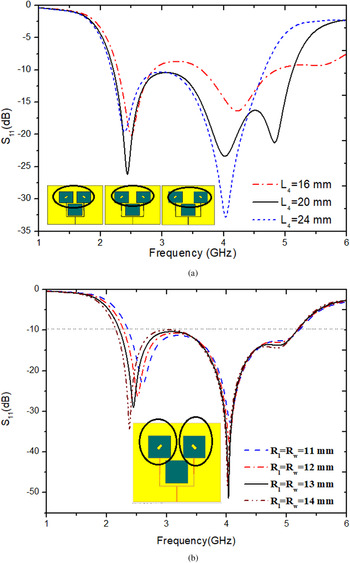
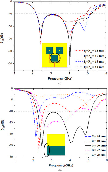
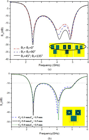
Power divider is designed with the targeted frequency band, so the spacing between the radiating patch feed is kept λ/4. Radiating patch spacing is varied from 16 to 24 mm. Maximum impedance bandwidth is achieved by selecting the distance of 20 mm between two radiating patches from the center as shown in Fig. 5(a). As depicted in Fig. 5(b); the radiating patch length and width are chosen as 12 and 13 mm, respectively, for achieving the optimum performance. The effect on reflection co-efficient by increasing the length and width of the parasitic patch from 11 to 14 mm, respectively, is shown in Fig. 6(a). It is observed that impedance bandwidth increases significantly by varying these parameters. The defected ground structure is used and the ground plane length parameter changes from 15 to 25 mm with a range of 5 mm. The wideband is achieved by introducing a defected ground structure in the antenna. As shown in Fig. 6(b), the bandwidth of the antenna can be controlled by this parameter where 20 mm length is preferred for the best output. The slot size is varied as shown in Fig. 7(a) and the effect on the reflection coefficient is observed. In the end, slot size changes, the S 11 curve shifts from a lower frequency band to a higher side with a significant effect on the input reflection coefficient values. The optimum length is of 3.0 mm and a width of 1.5 mm of the proposed antenna. Slot angle θ is also varied for 0°, 90°, and 45°. To achieve the best performance, the slot angle is kept at 45° in the radiating patch as shown in Fig. 7(b).
Effect on reflection coefficient (S 11) due to variations of (a) radiating patch spacing to center feed, (b) radiating patch width and length of an antenna.

Effect on reflection coefficient (S 11) due to variations of (a) parasitic patch and (b) ground length of an antenna.

Effect on reflection coefficient (S11) due to variations of (a) radiating slots angle and (b) radiating slots width and length of an antenna.

Results and discussion
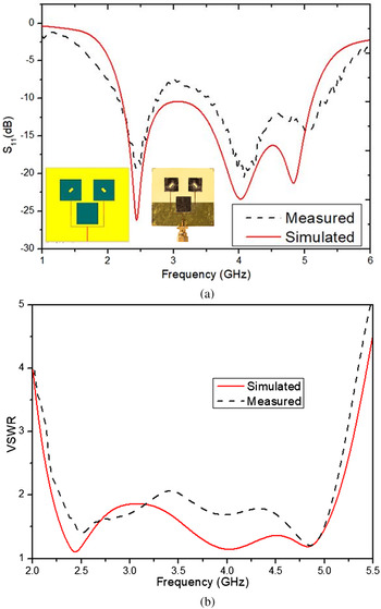
An antenna is designed for wideband operating frequency covering from 2.21 to 5.13 GHz bands. The simulated and measured reflection coefficient plot is shown in Fig. 8. Using the Anritsu MS2037C Vector Network Analyzer (VNA), the fabricated antenna input reflection coefficient is determined. To confirm our design method, a model antenna has been fabricated and tested. The S-parameter results of simulated and measured are compared in Fig. 8, and it is evident that these two outcomes are well matched. The antenna result shows that the proposed antenna has an estimated bandwidth of 2.21–5.13 GHz with S 11 <10 dB.
Comparison of a simulated and measured result of (a) input reflection coefficient and (b) VSWR.

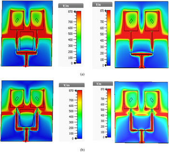
To understand the radiation characteristics, the E-field distributions with and without parasitic parch of the antenna at resonant frequencies 2.4 and 4.0 have been illustrated in Fig. 9, respectively. It is demonstrated that the additional parasitic patch integrated with the previous design is responsible for generating extra bend (i.e. 4 GHz resonant frequency). Moreover, it is also revealed that there is less coupling between the parasitic and the radiating patch. So, the additional patch does not disturb the main resonant band (i.e. 2.4 GHz resonant frequency) that is generated due to the coupling of the radiating patch. The current is mainly concentrated on the antenna with a half-wavelength resonator to generate respective operating bands. E-field distribution is to validate the design with the good agreement of linear polarization antenna, which ultimately enhances the performance of an antenna in terms of gain and radiation efficiency.
E-field distribution pattern with a parasitic patch (left side) and without parasitic patch (right side) of proposed antenna at (a) 2.4 GHz and (b) 4.0 GHz.

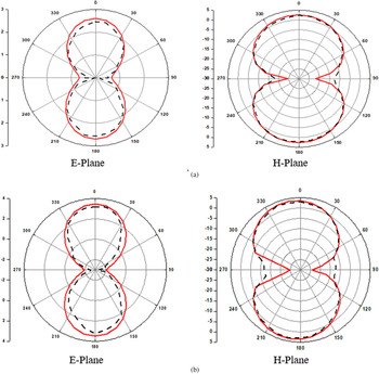
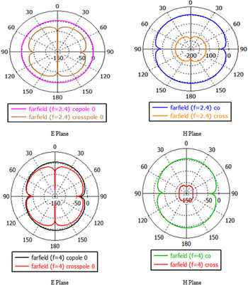
The radiation pattern exhibits in two dimensions of azimuth plane (E-plane) and elevation plane (H-plane) at 2.4 and 4.0 GHz frequencies as shown in Figs 10(a) and 10(b) along the ±z-axis at resonance frequencies 2.4 and 4.0 GHz at Φ = 0° and 90° where the gain of 2.71 and 3.50 dBi, respectively, is observed. The main lobe magnitude and 3 dB beamwidths are 2.71 dBi and 84.1°, 3.71 dBi and 71.6° for the frequencies 2.4 and 4.0 GHz, respectively. The axial ratio of an antenna is 40 dB. The simulated and measured radiation patterns are in good agreement. Figure 11 shows the co- and cross-polarization at 2.4 and 4.0 GHz, respectively. The results show that co- and cross-polarization of antenna radiation have more than 15 dB margin and tend to a pure linear polarized antenna.
Radiation pattern measured (dashed) and simulated (solid) at frequencies (a) 2.45 GHz and (b) 4.0 GHz.

2D radiation pattern of co- and cross-polarization at 2.4 and 4.0 GHz.

It can be depicted from Table 3 that simulated and measured results match well; however, slight discrepancy is observed in input reflection coefficient, directivity, and gain, due to imprecise placing of the graphene sheet on a G10 substrate as well as the effect of glue material used to fix on the substrate with the variation in antenna parameters such as dielectric constant, and fabrication of the hand-made prototype.
Comparisons of simulated and measured at resonant frequencies 2.4 and 4.0 GHz

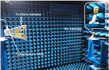
The prototype of antenna measurement is carried out in the anechoic chamber as shown in Fig. 12. The anechoic chamber has a frequency range of 800 MHz to 18 GHz to measure various antenna parameters. VNA port 1 is connected with horn antenna as a transmitter and port 2 is connected with DUT.
Measurement setup in the anechoic chamber.

As shown in Fig. 13, the frequency increases, the directivity of the antenna increases which results in a higher value of gain and efficiency with a lower and higher frequency value of 2.4 and 4.0 GHz, respectively. Measured results are in less agreement with the simulated results as the glue sheet of 10 μm is utilized for attaching patch and substrate material. However, there is no major effect of glue affecting the antenna characteristics and cutting edge of radiating and parasitic parch, which leads to deviation in the result. Due to the lower conductivity of graphene, a somehow low value of gain and radiation efficiency is achieved which can be overcome with the help of research in material science and modern fabrication technology.
Peak gain and radiation efficiency (η) of the proposed antenna.

Bending analysis
In an increasing number of wireless applications, versatile antennas are critical components, including wearable electronics and sensor systems. However, depending on the antenna design, substrate material, and other factors, flexing the antenna from its nominal straight configuration can impact performance. Realistically in smart device applications, as the devices are getting compact and slimmer, the antenna must be tested for its working on the curved surface. Therefore, the effects of bending are investigated through measurements in the E-plane and H-plane.
The bending measurement environment with an antenna prototype. The impedance performances of an antenna along the E- and H-plane in the bent conditions are almost the same with slight fluctuations when compared with the measured results. It is observed that the radiance performance of an antenna in terms of S 11 (dB) remains fair up to the bending angle of 14° in E-plane and 18° in H-plane as shown in Fig. 14. As the bending occurs in the patch, the effective length of the patch increases which affects the overall performance of the input reflection coefficient curve.
Reflection coefficient to frequency for bending analysis. Measured bending (left side), simulated bending (right side) of E-plane and H-plane, respectively.

Table 4 shows the antenna performance comparison with existing work. It has been observed that the proposed antenna is a combination of graphene and G-10 with a higher impedance bandwidth and reasonable gain. The proposed design is better in terms of gain compared in [Reference Álvarez, Cheung and Thompson7–Reference Lamminen, Arapov, With, Haque, Sandberg, Friedrich and Ermolov9] where the work is carried out using only graphene material; however, in [Reference Lago, Soh, Jamlos, Shohaimi, Yan and Vandenbosch27–Reference Ahmed, Tahir, Shamim and Cheema29], the antenna is designed using PLR (Flexible Pentangle Loop Radiator), copper laminated flexible sheet, and carbon nanotube, respectively. In [Reference Lago, Soh, Jamlos, Shohaimi, Yan and Vandenbosch27], a higher gain is achieved through the antenna that is 1.8 times bigger than the proposed antenna. Regardless of the limits of the flexible antennas, these flexible devices can be contrived to fulfil the futuristic demands of compact wireless devices where it can fit into any curvature surface. The proposed antenna is semi-flexible with a thickness of 0.2 mm only and bending analysis is also carried out to check its flexibility. Such a wideband antenna is suitable for smart wireless communication devices where space constraints are present.
Comparison of the proposed work with existing antennas

Conclusion
A wideband graphene-based antenna using a center parasitic patch antenna is proposed. The −10 dB impedance bandwidth is 79.56% (2.21–5.13 GHz). The antenna is extended to array applications with the help of parasitic coupling technique and the combination of graphene patch where the antenna size is kept within the constrained limits in order to make the antenna useful for tight curvature wireless device applications. The proposed antenna measured results with and without bending in terms of reflection coefficient, radiation pattern, and gain shows good agreement with the simulated results for the desired frequency band. So, the proposed antenna is suitable for semi-flexible applications in the field of smart wireless communication devices.
Acknowledgements
The research was performed and carried out at the ELARC-ELectromagnetics and Antenna Research Centre operated under BVM Engineering College, Vallabh Vidyanagar, Gujarat-India.
 Ronak Vashi is working as an Assistant Professor of Electronics and Communication Department, Birla Vishwakarma Mahavidyalaya Engineering College, V.V. Nagar since 2011. He did his Bachelor of Engineering from Sardar Patel University, Anand in 2008, and Master of Engineering from Gujarat Technological University, Ahmedabad, Gujarat in 2011. Currently, he is a research scholar from Charotar University of Science and Technology in graphene-based microstrip patch antennas area. He has published more than 15 research articles in the various fields of Electronics and Communication.
 Trushit Upadhyaya is working as a Professor and Head of Department at Electronics and Communication Engineering Department, Faculty of Technology and Engineering, Charotar University of Science and Technology (CHARUSAT), Changa. He did his Bachelor of Engineering from Gujarat University in 2004 and Masters of Engineering from the Institute of Telecommunication Research, University of South Australia, Adelaide in 2007, and Ph.D. from Charotar University of Science and Technology in Satellite Antennas in 2014. He was a visiting scientist at Physical Research Laboratory (PRL), Ahmedabad, Gujarat. His area of research is Antenna System Design and applied electromagnetics. He has carried out research and consultancy projects for Australian defense agencies, Indian Space Research Organization (ISRO), Gujarat Council on Science and Technology (GUJCOST), and private organizations.
 Arpan Desai received a B.E. degree in Electronics and Communication Engineering from Sardar Patel University, Gujarat, India, in 2006, M.Sc. Degree in Wireless Communication Systems from Brunel University, London, UK in 2008, and a Ph.D. degree from Charotar University of Science and Technology, Gujarat, India in the field of Transparent Antennas in January 2020. Currently, he is working as a Postdoctoral Researcher at Ton Duc Thang University, Ho Chi Minh, Vietnam. His current research interests include transparent antennas for MIMO applications, energy harvesting devices, transparent DRAs, and flexible wearable antennas. He is working as an Assistant Professor in Electronics and Communication Engineering Department, Charotar University of Science and Technology, Gujarat, India. He has published more than 40 research papers, mostly in SCI/Scopus journals and international conferences.