Introduction
Metasurface (MTS) antennas, which use MTSs as their primary radiators, offer enhanced radiation characteristics over traditional planar antennas in terms of bandwidth [Reference Pang, Zhao and Xu1], gain [Reference Huang, Guo and Yuan2], and beam shaping [Reference Zhou, Chen, Zhang, Wang and Guo3]. In addition to these advantages, the scattering properties – particularly the radar cross section (RCS) – of MTS antennas have also attracted increasing attention for military and stealth applications [Reference Wang, Li, Jiang, Shi, Tang, Zhou, Chen and Qiu4]. Currently, most low-RCS MTS antennas adopt a “scatter-first, radiate-later” strategy, in which a low-RCS MTS is initially designed without excitation and is subsequently integrated with an appropriate feed to realize the final antenna structure [Reference Jia, Liu, Gong, Zhang and Liao5–Reference Li, Liu and Jia8]. In [Reference Qiu and Xiao6] and [Reference Zheng, Guo, Ding, Akinsolu, Liu and Vandenbosch7], source-free low-RCS MTSs are first designed based on reflection phase cancellation and polarization cancellation, respectively. The corresponding antennas are then implemented by exciting the MTSs using coupled-fed slots.
In contrast to the above methods, this paper presents a novel “radiate-first, scatter-later” strategy aimed at reducing the RCS of an existing MTS antenna that already features desirable radiation performance. RCS reduction (RCSR) techniques for antennas generally fall into two categories. The first involves introducing advanced electromagnetic (EM) materials or structures, such as frequency-selective surfaces [Reference Parsha, Nandi and Basu9], artificial magnetic conductors [Reference Xue, Jiang and Gong10], and absorptive materials [Reference Liu, Cao, Gao, Zheng, Li and Yang11]. Although effective, these additional structures may increase the overall antenna size and introduce undesired losses. The second category adopts conventional techniques, such as shape modification and resistor integration [Reference Pozar12]. While these methods enable more compact designs, they generally lack systematic theoretical guidance.
Recently, the theory of characteristic mode (TCM; “CM” refers to characteristic modes) has been widely used to analyze the radiation performance of antennas in arbitrary shapes [Reference Chen and Wang13–Reference Elias, Soh, Al-Hadi, Akkaraekthalin and Vandenbosch15]. In contrast, only few studies employed TCM to directly control scattering properties, especially for MTS antennas. In [Reference Shi, Jia and Liu16], a new antenna scattering theory (AST) is presented based on the TCM. Both the structure mode scattering field and the antenna mode scattering field of an antenna can be expanded by its short-terminal modal E-fields. Based on the new AST, a general RCSR method is also proposed. However, the general method targets single-frequency cases, limiting its effectiveness for wideband RCSR. Moreover, for MTS antennas, the method requires further procedural refinement.
In this paper, a low-RCS antenna is proposed by applying a two-step RCSR operation to a conventional wideband MTS antenna, which serves as the reference. In the first step, the MTS of the reference antenna is reconfigured into a quasi-chessboard MTS based on the principle of reflection cancellation, aiming to realize wideband RCSR under various polarization incidences. In the second step, guided by the TCM-based AST, six slots are etched on the ground plane of the MTS antenna to further optimize the RCSR bandwidth under x-polarized incident. Compared with the reference antenna, the proposed low-RCS MTS antenna maintains its radiation characteristics within 5–6.5 GHz, while achieving monostatic RCSR ranges of 3.7–11.3 GHz and 4.7–11.3 GHz under x- and y-polarized incident waves, respectively. In addition to the specific antenna design, this work also introduces two methodological refinements: (1) an optimization of the TCM-based RCS reduction method in [Reference Shi, Jia and Liu16] tailored for MTS structures, and (2) a quantitative analysis of the scattering characteristics of MTS antennas enabled by TCM.
RCSR method based on TCM
In this section, we first introduce the TCM-based method reported in [Reference Shi, Jia and Liu16], and then present our novel refinements to enhance its applicability to MTS antennas. The core equations of the total antenna scattering field  ${{\mathbf{E}}^s}\left( {{Z_l}} \right)$ employed in this section are derived by embedding TCM into the classical AST [Reference Green17, Reference Liu, Fu and Gong18], as expressed by
 \begin{equation}{\mathbf{E}^s}\left( {{Z_l}} \right) = {\mathbf{E}^s}\left( {{Z_c}} \right) + {\mathbf{E}^a}\left( {{Z_l}} \right)\end{equation}
 \begin{align}{\mathbf{E}^s}\left( {{Z_c}} \right)& = \sum {\left( {a_n^s - Ta_n^r} \right)\mathbf{E}_n^{short}} ,\text{ }{\mathbf{E}^a}\left( {{Z_l}} \right) \nonumber\\
&= \sum {\left( {\frac{{{\Gamma _l}\left( {1 + {\Gamma _a}} \right)}}{{{\Gamma _l}{\Gamma _a} - 1}}Ta_n^r} \right)\mathbf{E}_n^{short}} \end{align}
 \begin{equation}T = \left[ {{\mathbf{E}^a}\left( 0 \right) \cdot {\mathbf{E}^r}{{\left( 0 \right)}^ * }} \right]/{\left| {{\mathbf{E}^r}\left( 0 \right)} \right|^2}\end{equation}
 \begin{equation}{\mathbf{E}^s}(0) = \sum {a_n^s\mathbf{E}_n^{short}} ,{\text{ }}{\mathbf{E}^r}(0) = \sum {a_n^r\mathbf{E}_n^{short}} \end{equation}
where
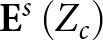 ${\mathbf{E}^s}\left( {{Z_c}} \right)$ and
 ${\mathbf{E}^a}\left( {{Z_l}} \right)$ are the structural mode and antenna mode scattering field,
 ${\mathbf{E}^s}(0)$ is the total scattering fields of antenna with short loads,
 ${\mathbf{E}^r}(0)$ is the radiation field of antenna with ideal voltage sources,
 $\mathbf{E}_n^{short}$ is the modal E-field of the nth CM with the short load,
Γl and Γa are the load and antenna reflection coefficients,
 $a_n^s$ and
 $a_n^r$ are the modal weighting coefficients (MWCs) under the excitation of external plane waves and internal voltage sources.Based on the above equations, a general method was also reported in [Reference Shi, Jia and Liu16] to reduce the RCS of an antenna while maintaining its radiation performance. For clarity, we provide a brief summary of the method in the following steps:
1) Solve all CMs at a given frequency with ideal voltage sources and plane-wave excitations, yielding
 $\mathbf{E}_n^{short}$,
$a_n^s$, and
$a_n^r$.
2) Identify the dominant CMs significantly affecting the radiation and scattering of the target antenna.
3) Analyze the characteristics of dominant CMs under excitations of ideal voltage sources and incident plane waves.
4) Obtain all coefficients in equations, and minimize the contribution of dominant CMs to
${{\mathbf{E}}^s}\left( {{Z_c}} \right)$ and
${{\mathbf{E}}^a}\left( {{Z_l}} \right)$ while keeping their contribution to
${\mathbf{E}^r}(0)$ as unchanged as possible.


The above general method is suitable for all antenna forms. However, for the RCSR of MTS antennas, its second step requires further refinement. This difficulty arises because MTSs exhibit a denser CM distribution than conventional planar radiators, making the determination of dominant CMs more challenging. Selecting too many CMs increases the complexity of the subsequent RCSR, whereas selecting too few prevents the accurate characterization of the antenna’s radiation and scattering properties. To address this issue, a novel CM selection strategy is proposed, as summarized in the following steps:
1) Exclude the CM with non-broadside radiation͑;
2) Compare remaining CMs and exclude those with both
$a_n^s$ and
$a_n^r$ one order of magnitude smaller than their corresponding maximum values;3) Combine the remaining CMs in any number and use Eq. (4) to calculate approximations of
${\mathbf{E}^s}(0)$ and
${\mathbf{E}^r}(0)$ for each combination; then, calculate the error between the approximated and simulated values; finally, CMs in the combination with the minimum mode number and the error less than 10% are selected as the dominant CMs.


The above strategy is exemplified by reducing the monostatic RCS in the broadside direction. Among the above steps, steps 1 and 2 can substantially narrow the selection range of dominant CMs; step 3 is to minimize the number of dominant CMs while ensuring the selected CMs can accurately characterize the radiation and scattering properties of the target antenna. Moreover, this strategy can be extended other complex structures in addition to MTSs.
Low-RCS MTS antenna design
Design procedure
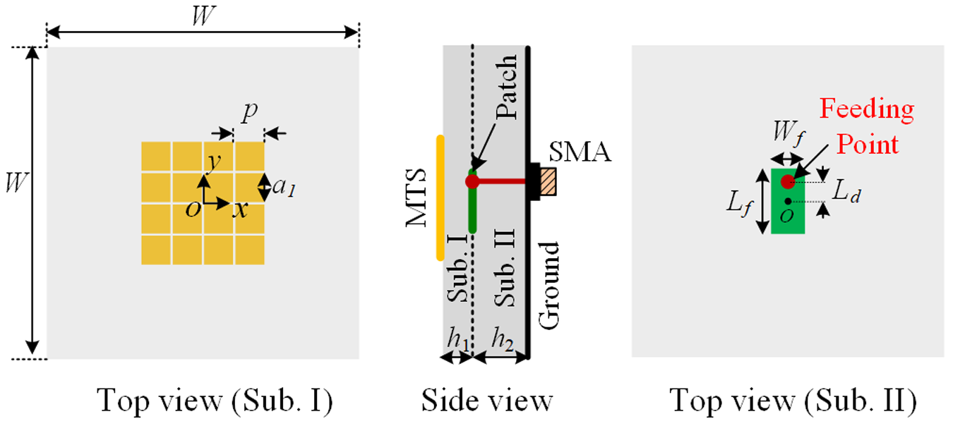
The proposed low-RCS MTS antenna is realized by backscattering suppression of a conventional wideband coupled-patch-fed MTS antenna, which serves as the reference antenna in this design. As shown in Fig. 1, the reference antenna consists of two-layer F4B220M substrates (εr = 2.2 and tan σ = 0.0009) with a distinct thickness (h 1 for Substrate I and h 2 for Substrate II) and identical lateral dimensions of W × W. A 4 × 4 square patch array MTS with a period of p and a cell size of a 1 × a 1 is printed on Substrate I. A 50-Ω SMA connector and a rectangular patch with dimensions of Lf × Wf are fabricated on the two sides of Substrate II. The inner conductor of the SMA is connected to the patch at (0 mm, Ld, h 2) thus forming a source to coupling feed the MTS.
Configuration of the reference antenna. W = 108, p = 10.8, a 1 = 10, Wf = 6.28, Lf = 12.25, Ld = 4.76, h 1 = 1, h 2 = 2. (Unit: mm).

Since several papers have already given the detailed design and analysis flow of the same type of antenna [Reference Liu, ZN and Xm19, Reference Liang, Jun and Yang20], this subsection only presents a brief introduction to the working principle of the reference antenna using the CM analysis (CMA). Fig. 2(a) shows the |MWC| curves of the first eleven CMs (MA1–MA11) of the reference antenna with a voltage source of 1 V. Compared with MA1 and MA2, the remaining CMs with very low |MWC| magnitudes can be neglected, indicating that the functioning CMs of the reference antenna are MA1 and MA2. Fig. 2(b) shows the normalized modal E-fields and currents of MA1 and MA2. MA1 and MA2 exhibit current distributions mainly on the MTS and the patch, and can thus be identified as the MTS mode and the patch mode, respectively. Both MA1 and MA2 feature in-phase current distributions and broadside radiation patterns. The wideband performance of the reference antenna is achieved by exciting the two CMs simultaneously.
Simulated CMA results of the reference antenna. (a) |MWCs| curves of the first eleven CMs. (b) Normalized modal E-fields and currents of MA1 and MA2.

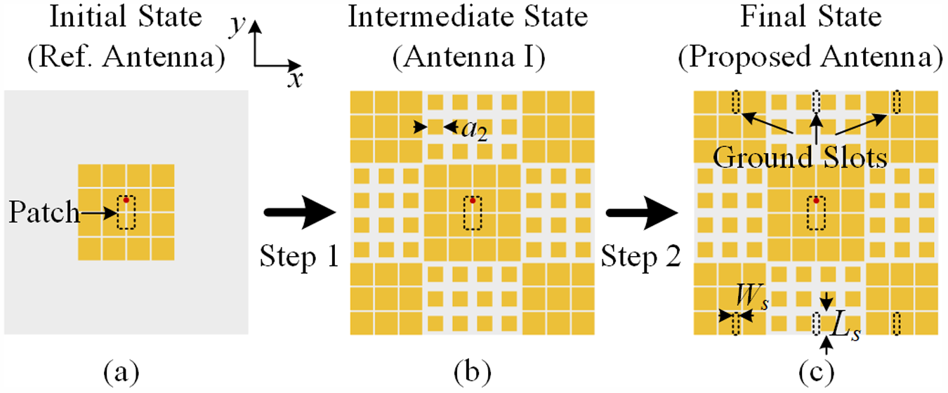
The design procedure of the proposed low-RCS MTS antenna involves three evolutionary iterations, as illustrated in Fig. 3. The initial state of the process is the reference antenna, shown in Fig. 3(a). Next, four corner arrays with 3 × 3 cells and four surrounding arrays with 4 × 3 cells are added to the MTS of the reference antenna, thus forming a new quasi-chessboard MTS. The cell dimensions of the corner and surrounding arrays are a 1 × a 1 and a 2 × a 2, respectively. An intermediate antenna, referred to as Antenna I, with the quasi-chessboard MTS is shown in Fig. 3(b). Finally, as shown in Fig. 3(c), the proposed low-RCS antenna is obtained by symmetrically etching six y-direction slots with dimensions of L s × W s on the ground of Antenna I.
Diagram of the design process for the proposed low-RCS MTS antenna. (a) Initial state: Reference antenna. (b) Intermediate state: Antenna I. (c) Final state: Proposed low-RCS antenna. A 2 = 6.7, Ls = 7.5, Ws = 2. (Unit: mm).

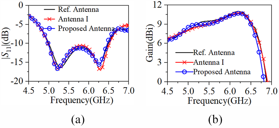
The above process aims to reduce the RCS of the reference antenna. For effective antenna RCSR, it is crucial to preserve the radiation characteristics of the reference antenna. Therefore, comparisons of the simulated |S 11|, gains, and radiation patterns among the reference antenna, Antenna I, and the proposed low-RCS antenna are depicted in Figs. 4 and 5, respectively. As shown in Fig. 4(a), |S 11| curves of the three antennas are almost identical, demonstrating an operating band of 5–6.5 GHz with |S 11| less than −10 dB. Within the operating band, the three antennas also feature same gains, as shown in Fig. 4(b). Additionally, similar radiation patterns at 5.2 and 6.3 GHz for the three antennas can be observed in Fig. 5. The beam tilting effect observed in the yoz-plane radiation pattern, particularly at higher frequencies, is caused by the asymmetry introduced by the offset feeding probe. In summary, the proposed RCSR process in Fig. 3 does not affect the radiation characteristics of the reference antenna.
Simulated |S 11| and gain comparisons between the reference antenna, Antenna I, and the proposed low-RCS antenna. (a) |S 11|. (b) Gain.

Simulated normalized co-polarized radiation pattern comparison between the reference antenna, Antenna I, and the proposed low-RCS antenna. (a) 5.2 GHz. (b) 6.3 GHz.

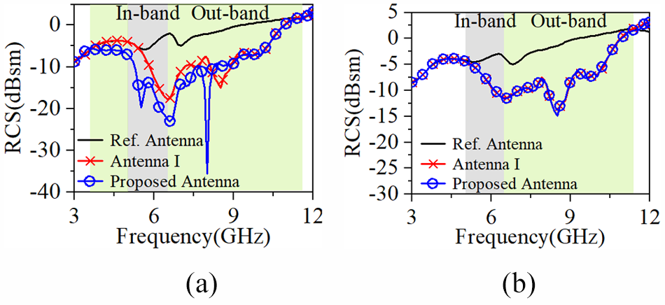
Figure 6 presents the simulated monostatic RCS results of the three antennas. Due to the feeding structure breaking the 90° rotational symmetry of the MTS, all antennas exhibit different scattering characteristics under orthogonal polarized incident waves. Compared with the reference antenna, Antenna I achieves in-band and out-of-band RCSR with a relative bandwidth (RBW) of 82.5% under the y-polarized incident wave. However, the RCSR range of Antenna I with a RBW of 69% (5.5–11.3 GHz) cannot cover the whole operating band (5–6.5 GHz) under the x-polarized normal plane wave incidence. Based on Antenna I, the proposed low-RCS MTS antenna extends the RBW to 101.3% under the x-polarized plane wave, achieving both in-band and out-of-band RCSR compared with the reference antenna.
Simulated monostatic RCS comparison between the reference antenna, Antenna I, and the proposed low-RCS antenna. (a) Under x-polarized normal incident plane wave. (b) Under y-polarized normal incident plane wave.

The first and second steps of the design process in Fig. 3 utilize the principle of reflection cancellation and the TCM-based RCSR method, respectively. The detailed information of these two steps will be discussed in the following subsections.
Step 1: wideband RCSR based on reflection cancellation
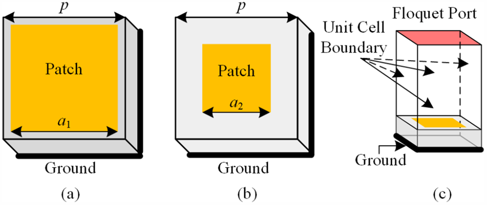
According to the principle of reflection cancellation in [Reference Chen, Balanis and Birtcher21], an RCS-reduced chessboard MTS array should contain two types of subarrays with identical reflection magnitude but opposite reflection phase (criterion: 180 ± 37°). To design subarrays, their unit cells must first be configured. Fig. 7(a) and (b) illustrate the proposed unit cells, denoted as U1 and U2. The reflection characteristics of the corresponding subarrays based on U1 and U2 are obtained through simulations in CST Microwave Studio, with the simulation set-up shown in Fig. 7(c).
Configurations of the two units (U1 and U2) and their simulation model. (a) U1. (b) U2. (c) Simulation set-up.

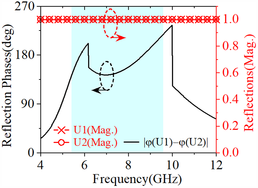
Among them, U1 is the basic unit cell of the MTS used in the reference antenna, while U2 is a modified version of U1 with different square patch dimensions. The identical metallic ground ensures that U1 and U2 have the same reflection magnitude (full reflection), while their opposite reflection phases are realized by adjusting the square patch size a 2 of U2 (optimized to 6.7 mm). Fig. 8 shows the reflection responses of U1 and the optimized U2. In the frequency range of 5.42–9.56 GHz, their reflection phase difference remains within 180 ± 37°, and their reflection magnitudes are both close to unity, thereby satisfying the phase-cancellation criterion.
Reflection response of U1 and U2.

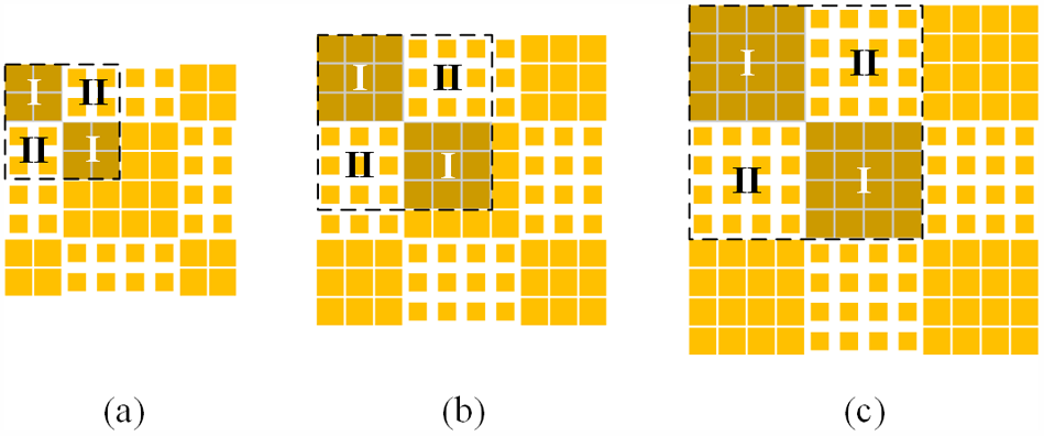
Three possible chessboard MTS configurations (MTSs I-III) formed by U1 and U2 are given in Fig. 9. Among them, MTSs I and III are standard chessboard MTSs with subarray scales of 2 × 2 and 4 × 4, respectively; MTS II with overlapped 3 × 3 subarrays can be regarded as a quasi-chessboard MTS. The central arrays of MTSs I-III are 4 × 4 square unit cells, aiming to maintain the radiation properties of the MTS in the reference antenna.
Three possible chessboard MTS configurations formed by U1 and U2. (a) MTS I. (b) MTS II. (c) MTS III.

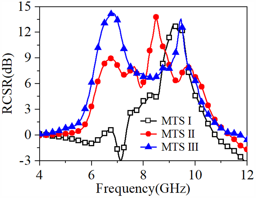
The scattering properties of MTSs I-III are compared with the 4 × 4 square patch array MTS of the same ground size, and the corresponding monostatic RCSR results under x- or y-polarized normal incidence are obtained. As shown in Fig. 10, MTS I exhibits a poor RCSR at lower frequencies, and the 6-dB RCSR bandwidth of MTSs II and III are comparable. However, considering both miniaturization and aperture efficiency, MTS II with a smaller size is ultimately selected.
Simulated monostatic RCSR of MTSs I-III under x- or y-polarized normally incident waves.

In addition to scattering properties, the proposed quasi-chessboard MTS (MTS II) should maintain similar radiation characteristics to those of the reference antenna under the same excitation. Therefore, a CMA is performed on Antenna I formed by MTS II and the coupled-fed patch. Fig. 11(a) shows the |MWC| curves of the first eleven modes (MB1-MB11) of Antenna I with a voltage source of 1 V, and normalized modal E-fields and currents of the excited modes (MB1 and MB2) are depicted in Fig. 11(b). A comparison between Figs. 2 and 11 shows that the functioning modes in the reference antenna and Antenna I feature similar results in |MWCs|, modal E-fields, and modal current distributions, indicating that Antenna I with MTS II keeps the same radiation mechanism as the reference antenna.
Simulated CMA results of Antenna I. (a) |MWCs| curves of the first eleven CMs, (b) normalized modal E-fields and currents of MB1 and MB2.

Step 2: further RCSR based on TCM
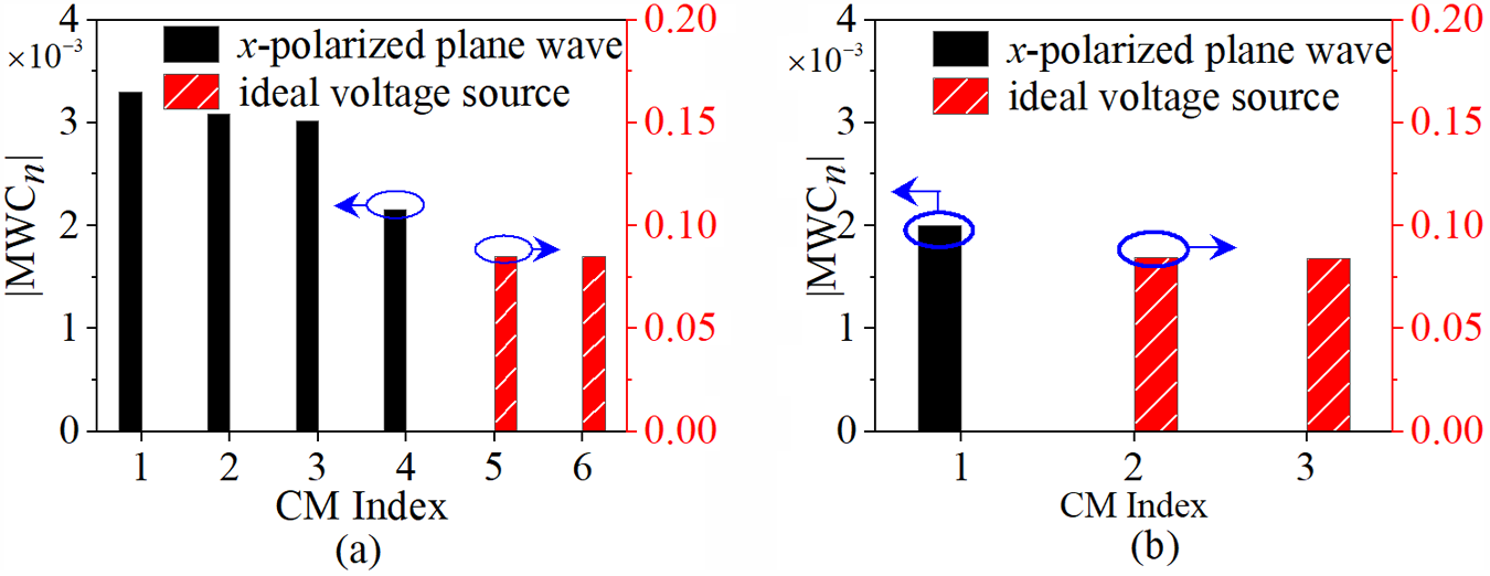
In this subsection, the TCM-based RCSR method in Section “RCSR method based on TCM” is introduced to further improve the in-band RCS performance of Antenna I for the x-polarized incident wave at frequencies below 5.5 GHz. Following the method, all CMs are solved at 5.5 GHz for Antenna I excited by the ideal voltage source and x-polarized incident wave, respectively. Then, according to the proposed CM selection strategy in Section “RCSR method based on TCM”, six modes (CM1-CM6) are determined as the dominant CMs of Antenna I. The errors between the approximate and simulated values for  ${\mathbf{E}^s}(0)$ and
 ${\mathbf{E}^r}(0)$ are less than 10% (3.96% for
 ${\mathbf{E}^s}(0)$, and 9.48% for
 ${\mathbf{E}^r}(0)$), satisfying the accuracy requirement.
Figure 12(a) shows the |MWCs| of CM1-CM6 at 5.5 GHz when Antenna I is excited by the x-polarized incident wave ( $a_n^s$) and ideal voltage source (
 $a_n^r$), respectively. Among the six modes, CM1-CM4 with a larger
 $a_n^s$ and neglectable
 $a_n^r$ can be excited by the x-polarized incident wave, referred to as the “scattering modes” of Antenna I; CM5 and CM6 with a neglectable
 $a_n^s$ and larger
 $a_n^r$ can be excited by the voltage source, referred to as the “radiation modes” of Antenna I.
of (a) CM1–CM6 for Antenna I and (b) CM1’–CM3’ for the proposed low-RCS MTS antenna excited by the x-polarized incident wave and ideal voltage source at 5.5 GHz, respectively.

Since the radiated E-field of Antenna I is y-polarized, no energy is coupled to the terminal load when it is excited by the x-polarized incident wave, and thus  ${\mathbf{E}^a}\left( {{Z_l}} \right)$ is zero. The total scattering of Antenna I can be expressed as follow according to Equations (1)–(4):
 \begin{equation}{\mathbf{E}^s}\left( {{Z_l}} \right) = {\mathbf{E}^s}\left( {{Z_c}} \right) = \sum {a_n^s\mathbf{E}_n^{short}} \end{equation}
For the RCSR, the value of  $\sum {a_n^s\mathbf{E}_n^{short}} $ should be decreased, which is dominated by the scattering modes. For the preservation of radiation, characteristics of the radiation modes and their corresponding
 $a_n^r$ should be kept unchanged.
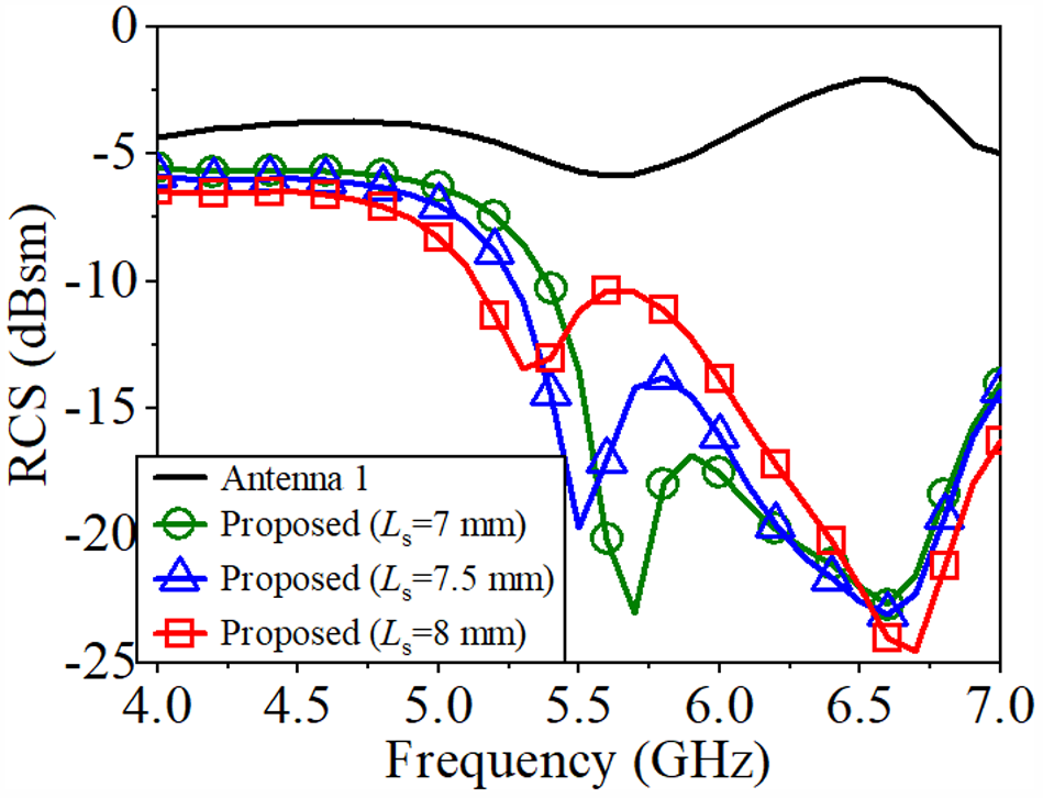
Figure 13 depicts the normalized modal currents of CM1–CM6. Except for CM4, modal currents of the remaining scattering modes of Antenna I are along the x-axis and mainly distributed at the midpoints and one-third positions of the upper and lower edges of the ground plane (six key locations), where the radiation modes exhibit no current distributions. To suppress the scattering modes while preserving current distributions of the radiation modes, six y-directed slots are etched at the six key locations, leading to the proposed low-RCS antenna. The purpose of introducing the slots is to extend the current paths of the scattering modes, thereby shifting their resonant frequencies and achieving RCS reduction. The optimized slot length of Ls = 7.5 mm provides the best reduction performance at 5.5 GHz, as shown in Fig. 14.
Normalized modal currents of CM1–CM6. (a) CM1–CM3. (b) CM4-CM6.

Simulated monostatic RCS comparison between the proposed MTS antenna with different Ls values.

The proposed low-RCS antenna is also tested by the two sources at 5.5 GHz, and only three dominant CMs (CM1’-CM3’) are found with  ${\mathbf{E}^s}(0)$ and
 ${\mathbf{E}^r}(0)$ errors less than 10%. As shown in Fig. 12(b), CM1’ with a larger
 $a_n^s$ is the only scattering mode of the proposed antenna, while CM2’ and CM3’ featuring a larger
 $a_n^r$ are the radiation modes of the proposed antenna. Fig. 15 depicts the normalized modal currents of CM1’–CM3’. Comparing Antenna I and the proposed low-RCS antenna, their radiation modes (CM5,6 and CM2,3’) have similar modal current distributions and comparable magnitude of
 $a_n^r$, and the value of
 $\sum a^s_n \mathbf{E}^{short}_n$ calculated by their corresponding scattering modes decrease from
 $12.84 \times {10^{ - 2}}{e^{j102.1}}\hat x$ to
 $3.29 \times {10^{ - 2}}{e^{j138.6}}\hat x$, showing a good RCSR performance at 5.5 GHz.
Normalized modal currents of CM1’–CM3’.

Results and discussions
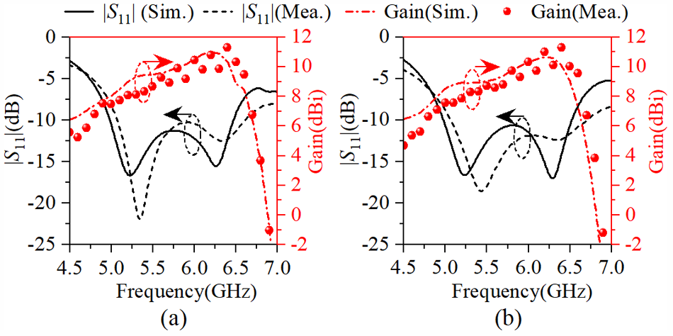
As shown in Fig. 16, the reference and the proposed low-RCS MTS antenna with the parameters in the captions of Figs. 1 and 3 were fabricated. The S-parameter and radiation characteristics of the two fabricated antennas were measured using an Anritsu MS46322 vector network analyzer and a far-field antenna test system, respectively. The simulated and measured |S 11| and gains of the reference and the proposed MTS antenna are plotted in Fig. 17(a) and (b), respectively. From Fig. 18, it can be observed that the two antennas exhibit nearly identical bandwidths (|S 11| < −10 dB) and gains. Compared to their respective simulation results, the measured operating ranges of the two antennas both show a slight blueshift, due to fabrication errors caused by SMA solder joints on the patch layer in Fig. 16.
Fabricated photographs of the reference and the proposed low-RCS MTS antenna. (a) Reference MTS antenna. (b) Proposed low-RCS MTS antenna.

Simulated and measured |S 11| and gains of the reference and the proposed low-RCS MTS antenna. (a) Reference MTS antenna. (b) Proposed low-RCS MTS antenna.

Simulated and measured normalized patterns of the reference MTS antenna. (a) 5.2 GHz. (b) 6.3 GHz.

Figures 18 and 19 present the simulated and measured normalized radiation patterns of the reference and the proposed MTS antenna at 5.2 and 6.3 GHz, respectively. The measured patterns of both antennas show good agreement with the simulations and exhibit strong broadside radiation characteristics at both frequencies. The measured cross-polarization levels in the boresight direction are better than 30 dB for both antennas, and the front-to-back ratios exceed 20 dB. By comprehensively comparing the results in Figs. 18 and 19, it can be concluded that the proposed RCSR design successfully maintains the radiation performance of the reference MTS antenna.
Simulated and measured normalized patterns of the proposed low-RCS MTS antenna. (a) 5.2 GHz. (b) 6.3 GHz.

To evaluate the scattering characteristics of antennas, a monostatic RCS measurement system was set up in an anechoic chamber. The schematic diagram and the corresponding photograph of the setup are Fig. 20(a) and (b), respectively. Two identical linearly polarized horn antennas, serving as the transmitter and receiver, are arranged in close spacing. The tested antenna is placed in the far-field region of the measurement system. Using the established measurement setup, the fabricated reference and proposed low-RCS MTS antennas were tested separately. The RCSR was then obtained by subtracting their measured results.
Schematic and photograph of the RCS measurement system. (a) Schematic. (b) Photograph.

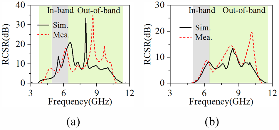
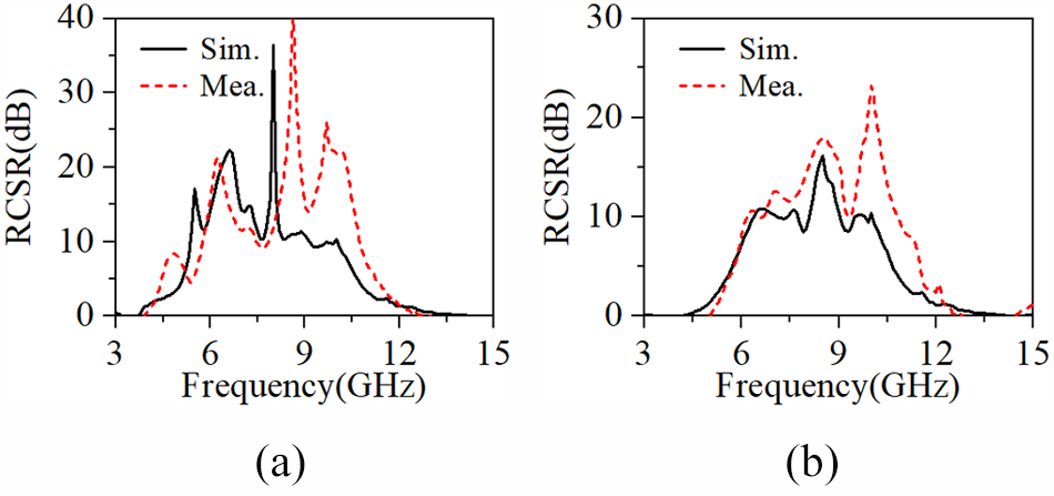
The simulated and measured monostatic RCSR of the proposed low-RCS MTS antenna compared with the reference antenna is shown in Fig. 21. The measured RCSR ranges (>0 dB) under x- and y-polarized normal incident plane waves are 3.92–10.75 GHz (93.12%) and 4.9–11 GHz (76.73%), respectively. Although some discrepancies caused by fabrication and measurement errors exist between the simulated and measured RCSR curves, the overall reduction bandwidths are in good agreement. Both simulation and measurement demonstrate that significant RCSR is achieved not only within the operating band but also across a wide out-of-band frequency range.
Simulated and measured RCSR of the proposed antenna compared with the reference antenna under orthogonal polarized incidences. (a) x-polarized wave. (b) y-polarized wave.

To enable a fair comparison with other published low-RCS MTS antennas, the scattering performance of the proposed low-RCS MTS antenna is also compared with a metallic plate of 108 × 108 mm2. As shown in Fig. 22, the simulated RCSR (>0 dB) ranges under x- and y-polarized normal incident plane waves are 3.8–14.2 GHz (116%) and 4.3–14.1 GHz (107%), respectively. The corresponding measured reduction bandwidths are 4–12.9 GHz (105%) and 4.8–12.8 GHz (91%). As previously noted, fabrication and measurement errors lead to some discrepancies between the measured and simulated curves. Nevertheless, both results exhibit similar trends and RCSR performances.
Simulated and measured RCSR of the proposed antenna compared with a metallic plate under orthogonal polarized incidences. (a) x-polarized wave. (b) y-polarized wave.

Comparisons between the proposed antenna and other state-of-the-art low-RCS MTS antennas are tabulated in Table 1. The listed RCSR RBWs are defined with respect to metallic plates of the same size. Compared with other designs, the proposed antenna exhibits wideband performance in both impedance matching and RCSR. In addition, it maintains a relatively compact size while delivering competitive in-band peak gain, thus offering a more balanced performance in terms of bandwidth, efficiency, and overall antenna dimensions.
Comparison with other low-RCS MTS antennas

 ${\lambda _L}$: the wavelength in the lowest operating frequency.
Conclusion
In this paper, a wideband MTS antenna with low RCS is proposed. Unlike previously reported low-RCS MTS antennas, the scattering characteristics of the proposed antenna are directly evaluated using the TCM. The proposed design is achieved by reducing the RCS of an existing wideband MTS antenna, which serves as a reference. The RCSR process consists of two steps. First, the MTS of the reference antenna is reshaped into a quasi-chessboard configuration to enable wideband RCSR through reflection cancellation. Second, six slots are etched into the ground plane to further extend the RCSR bandwidth under x-polarized incidence, based on a TCM-based AST. Simulation results demonstrate that the proposed MTS antenna achieves effective in-band and out-of-band RCSR while maintaining radiation characteristics comparable to those of the reference antenna. The presented approach also shows potential for extension to other low-RCS antenna designs.
Conflict of interest
We declare that all authors have no conflicts of interest.

Chao Huang was born in Xi’an, Shaanxi, China, in March 1994. He received the B.S. degree and M.S. degree from the School of Electronic Engineering, Xidian University, Xi’an, China, in 2016 and 2019, respectively. He received the Ph.D. degree in the School of Electronics and Information, Northwestern Polytechnical University, Xi’an, China, in 2025. He is currently an engineer with the AVIC Xi’an Aircraft Industry Group Company Ltd. His research interests include characteristic mode theory in high performance or multifunctional antennas.

Chenjiang Guo was born in February 1963. He received the B.S. degree, M.S. degree and Ph.D degree from the Northwestern Polytechnical University, Xi’an, China, in 1984, 1987, and 2007, respectively. In 1987, he joined Northwestern Polytechnical University, China, as an Assistant Professor, where he is a Full Professor. His current research interests include electromagnetic metasurface, antenna theory and design, microwave circuit design, electromagnetic compatibility.

Jingyi Hao was born in Jinzhou, Liaoning, China, in January 1982. He received the B.S. degree in Shenyang Aerospace University, Shenyang, Liaoning, in 2004. He is currently a senior engineer with the AVIC Xi’an Aircraft Industry Group Company Ltd. His current research interests include avionics theory and testing technologies.

Rui Cai was born in Zhangye, Gansu, China, in December 1988. He received the B.S. degree from the School of Electronic Engineering, Xidian University, Xi’an, China, in 2011. He is currently a senior engineer with the AVIC Xi’an Aircraft Industry Group Company Ltd. His current research interests include electromagnetic theory and testing technologies.

Yue Zhang was born in Jiuquan, Gansu, China, in February 1994. She received the B.S. degree in Hexi University, Zhangye, China, in 2016. She received the M.S. degree in Shaanxi Normal University, Xi’an, China, in 2019. She is currently an assistant engineer with the AVIC Xi’an Aircraft Industry Group Company Ltd. Her research focuses on radar-absorbing materials.