Introduction
Over the past decades, the world has been going through an unprecedented communication revolution, which motivates the development of wireless communication devices. Meanwhile, antenna plays a critical role in wireless communication. With the advent of the 5 G era, there is a soaring demand for multiple-input-multiple-output (MIMO) antennas which have the advantages of high reliability, large gain, and wide bandwidth. More attention, especially in recent years, has been concentrated on the MIMO antenna design.
Two main thorny issues encountered in the design process of MIMO antenna are the gain improvement and the isolation enhancement. In order to address the issues mentioned above, various techniques have been widely studied in recent years. In [Reference You, Gao, Zhou and Zhao1], high isolation between radiating elements has been achieved by placing two elements as mirror symmetrical orientation on different sides of the substrate. A slot on the ground plane was cut to achieve better isolation in [Reference Huang, Dong, Cai, Li and Liu2–Reference Shen, Zhang, Jiao and Yan4]. Fractal uniplanar compact electromagnetic bandgap (UC-EBG) structure and cross slots were introduced to enhance the isolation [Reference Yang, Liu, Xu and Gong5]. To improve the isolation, grounded stubs and multiple slots are employed in [Reference Lee, Kim and Jang6–Reference Chen, Lin, Wang, Ge, Li, Per and Sim10]. Defected ground structure (DGS) was utilized to reduce the mutual coupling between two antenna elements [Reference Kim and Choi11]. Dual band decoupling network was presented to improve the isolation, such as coupled resonators [Reference Zhao and Wu12] and T-sub circuits [Reference Sui and Wu13]. Metal vias were placed into the radiating elements in reference [Reference Pan, Qin, Sun and Zheng14] to change the excited electromagnetic field distributions, and thus decreased the mutual coupling between two radiating elements effectively.
Moreover, many techniques have been proposed to improve the gain of MIMO antennas [Reference Jiang, Si, Hu and Lv15–Reference Squadrito, Zhang and Pedersen19]. In [Reference Jiang, Si, Hu and Lv15], high gain was realized by integrating three pairs of metamaterial (MTM) arrays. Gain can be enhanced by artificial magnetic conductors (AMC) ground plane [Reference Yang, Wang, Che and Wang16]. Radiating performance has been improved a lot by the L-shaped probe array [Reference Wang, Guo and Sheng17]. In [Reference Wang, Liu, Chen, Li and Shi18], an H-shaped resonator was used to improve the gain. Two circular slots were applied to increase the gain in [Reference Squadrito, Zhang and Pedersen19].
In this paper, a dual-band MIMO antenna operating at both 3.5 and 4.5 GHz frequency bands is proposed. Two radiating elements are printed face to face on a rectangle substrate. Each radiating element includes a T-shaped slot and a small L-shaped slit. The measured impedance bandwidths of −10 dB reflection coefficients are 500 MHz (3.3–3.8 GHz) and 1500 MHz (4.3–5.8 GHz), and the measured isolation is better than 15 dB.
Antenna design
As shown in Fig. 1, the proposed MIMO antenna is fabricated on a FR4 substrate with ε r of 4.4, tanδ of 0.02, and the thickness of 1.59 mm. The proposed antenna consists of two skew symmetry open-loop square radiating elements printed on the top side of the substrate, and two rectangle ground planes with rectangle slot are fabricated on the bottom side of the substrate. Each radiating element contains a T-shaped slot and a small L-shaped slit. The small L-shaped slit mainly resonates at 3.5 GHz band, while the T-shaped slot inspires 4.5 GHz band. An I-shaped isolation structure with six small rectangle slots (0.5 mm × 0.3 mm) is applied to decrease the coupling between two elements. And the dimension of each antenna element is only 11.75 mm × 11.75 mm (0.1754λ 0 × 0.1754λ 0, λ 0 is the free-space wavelength at the frequency of 4.5 GHz).
Configuration of the proposed antenna. (a) top view. (b) bottom view.

Parameter analysis
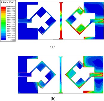
To further understand the principle of the proposed MIMO antenna, the electric field distribution at two resonant frequencies is illustrated in Fig. 2. In Fig. 2(a), the simulated strongest electric field distribution at 3.5 GHz is mainly concentrated at the lower corner of the radiation element and the isolation structure. The lower intensity of electric field is scattered among the inner upper and right portion of DGS. As shown in Fig. 2(b), the larger intensity of electric field at 4.5 GHz is distributed at the two corners of the radiation element. Therefore, the geometry parameters affecting the proposed MMIO antenna performance can be optimized according to the electric field distribution.
Simulated E-field distribution at two resonant frequencies. (a) 3.5 GHz. (b) 4.5 GHz.

Figure 3 illustrates the simulated S-parameters of the proposed antenna with different value of W8. As can be seen from Fig. 3(a), both resonant frequencies shift toward higher frequencies when the value of W8 becomes larger. As shown in Fig. 3(b), the isolation of the proposed antenna at the higher frequency band is affected by the value of W8. The optimized value of W8 is 0.6 mm.
Simulated S-parameters of the proposed antenna with different value of W8.

The optimization of the value of W10 is exhibited in Fig. 4. S 11 and S 21 parameters almost remain unchanged for the lower frequency band with different value of W10. Therefore, the value of W10 can be effectively used to optimize S 11 and S 21 parameters of the higher frequency band. The most appropriate value of W10 is 1.0 mm.
Simulated S-parameters of the proposed antenna with different value of W10.

Simulation and measurement result
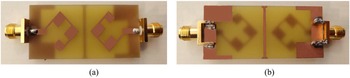
The optimized configuration of the proposed antenna is shown in Table 1. The photograph of the fabricated antenna is presented in Fig. 5.
Parameters of the proposed antenna (in millimetres).

Photograph of the fabricated antenna. (a) top view. (b) bottom view.

Figure 6 shows the simulated and measured reflection coefficient. The measured impedance bandwidths of −10 dB reflection coefficients are 500 MHz (3.3–3.8 GHz) and 1500 MHz (4.3–5.8 GHz), respectively. Some deviation of S 11 between simulation and measurement is resulted from the soldering process of SMA connectors at the higher frequency band. Therefore, the operating frequency bands of the proposed antenna can cover 5 G New Radio n78 (3.3–3.8 GHz), n79 (4.4–5 GHz) and WLAN (5.15−5.35 GHz) frequency bands. As shown in Fig. 7, the measured isolations at the lower frequency band and the higher frequency band are better than 15 and 17 dB, respectively. Some divergence between the measured and simulated results occurs due to the fabrication errors and losses.
Simulated and measured reflection coefficients of the proposed antenna.

Simulated and measured isolation of the proposed antenna.

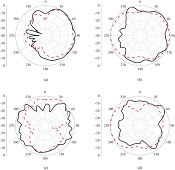
To further demonstrate the performance of the proposed antenna, Fig. 8 presents the normalized measured antenna radiating patterns at both 3.5 and 4.5 GHz. Since the presented antenna has a symmetrical structure, port 1 is excited while port 2 is terminated by a 50 Ω load during the radiating pattern measurement process. As depicted in Fig. 8, the black solid and red dash lines represent co-polarization and cross-polarization, respectively.
Measured 2D radiating patterns of the proposed antenna.(a) 3.5 GHz XOY-plane. (b) 3.5 GHz YOZ-plane. (c) 4.5 GHz XOY-plane. (d) 4.5 GHz YOZ-plane.

To better demonstrate the MIMO potentials of the presented antenna, ECC was calculated. As one critical standard to assess the performance of MIMO antenna, ECC is a measurement indicator of the correlation level between two radiating elements. The lower ECC is, the better the MIMO performance can be obtained. It is a consensus that the value of ECC must be lower than 0.5 to provide an excellent diversity gain [Reference Vaughan and Andersen20]. The ECC between antenna element i and antenna element j can be calculated by the far field pattern as shown in equation (1). The Eθ /ϕ,i/j (θ,ϕ) in equation (2) is the θ (or ϕ)-polarized electric far-field patterns of any two antenna elements in a spherical coordinate.

where:

Moreover, ECC can also be estimated by the following equation (3):

where S ii is the reflection coefficient of antenna element i, and S ij (i ≠ j) represents the transmission coefficient between two antenna elements. Equation (3) can be used only under some assumptions such as a lossless antenna in a rich isotropic multipath (RIMP) scenario. Equation (3) is selected to make a rough estimation of ECC. The real and imaginary part of both S 11 and S 21 were measured by the Vector Network Analyser (VNA) N5224A. Since the proposed antenna has a quiet symmetrical structure, only Port 1 is measured. The calculated ECC of the antenna is depicted in Fig. 9. The calculated ECCs of the antenna are below 0.02 in both operating bands, which is far smaller than 0.5.
Simulated and measured ECC of the proposed antenna.

In Fig. 10, the peak gain and radiating efficiency were illustrated. The measured peak gain of the proposed antenna is nearly 4.5 and 5 dBi at 3.3–3.8 GHz and 4.3–5.8 GHz frequency bands, respectively. The measured efficiency is better than 55% in both operating bands. A performance comparison between the proposed antenna with state-of-the-art 5G/WLAN MIMO antennas is depicted in Table 2. The main contribution of our work is that we propose a dual-band 5G/WLAN MIMO antenna with lower ECC, smaller size and wider frequency bandwidths.
Gain and efficiency of the proposed antenna.

State-of-the-art of MIMO antenna.

Conclusion
This paper presents a compact dual-band MIMO antenna for 5 G/WLAN applications. The measured −10 dB bandwidth are 500 MHz (3.3–3.8 GHz) and 1500 MHz (4.3–5.8 GHz), which can cover the 5 G New Radio n78 (3.3–3.8 GHz), n79 (4.4–5 GHz) and WLAN (5.15 −5.35 GHz) frequency bands. The measured isolation between two radiating elements is better than 15 and 17 dB at both operating frequency bands, respectively. The proposed antenna has a peak gain of 4.5 dBi at the lower frequency band and 5 dBi at the higher frequency band, respectively. The measured efficiency is almost 55% and the measured ECC values are smaller than 0.02 in both operating bands. Therefore, the presented antenna can be regarded as a good candidate for 5G/WLAN mobile terminals.
Acknowledgements
This work was funded in part by the National Natural Science Foundation of China under Grant No. 61671330, the Science and Technology Department of Zhejiang Province under Grant No. LGG19F010009, and Wenzhou Municipal Science and Technology Program under Grant No. C20170005 and No.2018ZG019.
 Gui Liu received his B.S. degree from South China University of Technology in 1997, the M.S. degree from Sun Yat-sen University in 2003, and the Ph.D. degree from Illinois Institute of Technology in 2011. He is currently a professor of Wenzhou University, Wenzhou, China. His research interests include RF integrated circuit design, microwave device and antenna design.
 Chuanba Zhang received the B.S. degree from Nan Yang Institute of Technology in 2019, he is currently pursuing his M.S. degree in Wenzhou University. His current research interests include RF integrated circuit design and antenna design.
 Zhuoni Chen received her B.S. degree from Guangdong Ocean University in 2020. She is currently pursuing her M.S. degree in Wenzhou University. Her research interests include RF integrated circuit design and antenna design.
 Bo Chen received the B.S. degree in microelectronics from Peking University and the M.S. degree in microelectronics and solid-state electronics from institute of microelectronics of the Chinese Academy of Science, Beijing, China. He is currently an assistant professor in Wenzhou University, Wenzhou, China. His research interesting includes hardware security, hardware obfuscation, and antenna design.