
1. Introduction
The wave energy resource is significant and could supply 10–20 % of the world's energy demand (Aderinto & Li Reference Aderinto and Li2018). Different technologies have been proposed to extract renewable energy from ocean current and ocean waves (Babarit Reference Babarit2017). Still, few technologies can harvest energy from these two resources concurrently. One promising candidate is to use the coupling between fluid and structure in terms of vortex-induced vibration, galloping and fluttering response to either directly enable energy transfer from the incoming current (Zhu & Peng Reference Zhu and Peng2009) or actively modify the impedance of the device to capture ocean energy more efficiently (Falnes & Kurniawan Reference Falnes and Kurniawan2020; Ringwood Reference Ringwood2020). Deployable and flexible structures are good candidates to enhance the performance of energy harvesting devices while addressing the reliability and survivability challenges facing conventional designs based on rigid-body systems (Pecher & Kofoed Reference Pecher and Kofoed2017). The flexible wave energy converters such as the wave carpet (Koola & Ibragimov Reference Koola and Ibragimov2003; Alam Reference Alam2012) and piezoelectric wave energy converter (Jbaily & Yeung Reference Jbaily and Yeung2015) use the cyclic wave action to generate an alternating current electrical energy. These devices are easily adjustable and can be employed as wave attenuation devices and hybrid wave/current energy harvesters on fixed and moving marine structures. They can also be combined with other devices to enhance the locomotion of marine vehicles (Collins et al. Reference Collins, Hossain, Dettmer and Masters2021).
A flexible thin structure with distributed wave energy converters, analogous to a piezoelectric plate, is a canonical rendition of a wide range of the above multi-segmented flexible energy harvesting concepts (Erturk & Inman Reference Erturk and Inman2011). Piezoelectric thin structures are employed to harvest wave energy directly (Viet, Wu & Wang Reference Viet, Wu and Wang2017; Mutsuda et al. Reference Mutsuda, Tanaka, Doi and Moriyama2019), or they are used as a model to study the asymptotic response of multi-segmented conventional devices, such as M4 and Pelamis, wherein the energy is captured from differential deformation of adjacent segments (Stansby, Moreno & Stallard Reference Stansby, Moreno and Stallard2015; Peng et al. Reference Peng, Qiu, Meng, Chen, Lundrigan and Gardiner2020). These systems, in the limit of many interconnecting bodies, resemble the canonical piezoelectric plate with infinitesimal neighbouring electrical circuits in which a simple mathematical model can capture the role of mechanical-to-electrical conversion as well as the resistance capacitance and inductance components of the electrical circuit (Doaré & Michelin Reference Doaré and Michelin2011; Michelin & Doaré Reference Michelin and Doaré2013). Another related power harvesting system with similar principles is electro-active polymers (Babarit et al. Reference Babarit, Gendron, Singh, Mélis and Jean2013). All of these technologies have the advantage of transforming the mechanical actuation to electrical output directly, and therefore eliminating the need for including complex mechanical power take-off and power conversion systems (Renzi et al. Reference Renzi, Michele, Zheng, Jin and Greaves2021). The coupled hydro-electro-mechanic response of these structures has been studied near the free surface Renzi (Reference Renzi2016), next to the vertical wall (Zheng et al. Reference Zheng, Meylan, Fan, Greaves and Iglesias2020), and as an array of energy harvesters (Mutsuda et al. Reference Mutsuda, Watanabe, Azuma, Tanaka and Doi2013). Furthermore, previous research has explored using flexible plates as adjustable floaters and wave energy dissipation devices (Selvan & Behera Reference Selvan and Behera2020; Zheng et al. Reference Zheng, Meylan, Zhang, Iglesias and Greaves2021). In particular, the use of floating plates for harvesting wave energy is explored in Michele et al. (Reference Michele, Buriani, Renzi, van Rooij, Jayawardhana and Vakis2020) and Michele, Zheng & Greaves (Reference Michele, Zheng and Greaves2022), wherein a theoretical model based on structural mode shapes of a circular plate is proposed to examine the wave power extraction capacity of these concepts.
In a recent study conducted by Mougel & Michelin (Reference Mougel and Michelin2020), it was discovered that the flapping dynamics of a flexible plate in potential flow is influenced significantly by the presence of the free surface and resonant conditions between the plate and surface gravity waves. Moreover, previous research by Renzi (Reference Renzi2016) highlighted that optimal energy harvesting by a piezoelectric plate in a purely harmonic incoming wave relies on constructive matching between the plate's natural frequency and the wave frequency. Building upon these findings, the current study explores how the flow interaction among a flexible piezoelectric plate, its wake, and the free surface can be utilized to manipulate the dynamic characteristics of hybrid wave/current energy harvesters and enhance their energy capturing efficiency.
A closely related problem is a hydrofoil oscillation near the free surface as a passive propulsor or energy harvesting device (Rozhdestvensky & Ryzhov Reference Rozhdestvensky and Ryzhov2003). Grue, Mo & Palm (Reference Grue, Mo and Palm1988) and Crimi & Statler (Reference Crimi and Statler1964) conducted a mathematical study on the propulsion of a moving and oscillating foil in close proximity to a free surface under two different scenarios: with incoming waves and without incoming waves. In the absence of incoming waves and a stationary free surface, the study revealed that the momentum transfer between the foil and the flow could result in either positive or negative values, leading to an increase or decrease in the thrust force. However, regardless of the specific scenario, the generation of waves always results in a significant amount of wasted energy. With the presence of surface waves, it was shown that potentially, up to 75 % of the incoming wave energy could be captured and leveraged towards propulsion. Similarly, it has been explored that prescribed deforming fishes near the free surface can benefit from the surface waves to adjust their propulsion (Reece & Siekmann Reference Reece and Siekmann1964; Fish & Rohr Reference Fish and Rohr1999; Shoele & Zhu Reference Shoele and Zhu2015). It is interesting to study how through proper selection of structural parameters, one can take advantage of the combined effects of current and wave for energy harvesting applications and achieve optimal operating conditions.
This paper employs a mathematical model of a flexible piezoelectric plate placed at a finite depth below the free surface to study the energy harvesting regimes. Wide ranges of incoming wave frequency, submergence depth and current are investigated. The effects of mechanical and electrical parameters on the energy transfer between flow and structure are quantified, and major response modes are examined. Finally, the conclusion and discussion about future directions are presented.
2. Problem formulation
2.1. Configuration
We consider the dynamics of a two-dimensional thin neutrally buoyant flexible plate of length  $2b$, with
 $b$ being the half-chord length placed in a uniform axial flow of velocity
 $u$ and density
 $\rho$ at a distance
 $H$ beneath the mean free surface (figure 1). The flow is assumed to be incompressible, inviscid and infinitely deep. The infinite depth assumption is made to simplify the theoretical modelling. In addition, the infinite depth assumption is appropriate for the current problem since, in the anticipated energy harvesting applications, the plate's length is much smaller than the water depth. Here, we assume the clamped boundary condition at the leading edge, and the free boundary condition at the trailing edge of the plate. In addition, it is considered that both surfaces of the plate are covered with infinitesimal piezoelectric patches with segmentation lengths much smaller than
 $b$. Each segment is attached to an independent energy harvesting system with linear resistance
 $R$, capacitance
 $C$, and inductance
 $L$ elements. The sandwich plate's mass per unit length is
 $m_s$, and its equivalent bending stiffness is
 $k_b$. Since the plate is very thin, the inertial effect of the plate mass is negligible and therefore is not considered.
Schematic configuration of a piezoelectric plate beneath the free surface in uniform flow exposed to an incident harmonic wave. In this study, the incident wave is assumed to propagate in the direction of the current, which is also referred to as the head wave (Grue & Palm Reference Grue and Palm1985).

2.2. Governing equations
It is assumed that the oscillation amplitudes and the amplitudes of the incoming waves are small. This allows us to use linearized equations of the plate and flow boundary conditions. We denote the vertical deflection of the plate with  $Y (x,t)$, and the electric voltage difference between a small piezoelectric patch on the top and bottom surfaces of the flag with
 $V (x,t)$. The piezoelectric patch is connected to the output circuit with resistance and inductance elements, as shown in figure 1. It is assumed that
 $Y (x,t) =O(\epsilon _p b) \ll b$ for a small
 $\epsilon _p$ value. Here,
 $\epsilon _p$ is related to incoming wave amplitude as
 $\epsilon _p\approx {A_0}/{b}$, with
 $A_0$ being the incoming wave amplitude. For a thin submerged plate, the structural inertial effects are negligible compared to the bending effect and fluid forces; therefore, the flag is assumed to be massless. Furthermore, it is assumed that the gravity and buoyancy forces cancel each other for the neutrally buoyant flag considered in this study, and the initial configuration of the plate is force-free. The non-dimensional variables shown with
 $\hat {\ }$ are defined as
 \begin{equation} \hat{x}=\frac{x}{b}, \quad \hat{Y}=\frac{Y}{b}, \quad \hat{t}=\frac{u t}{b}, \quad \hat{V}=\frac{V}{u\sqrt{\rho b/C}}. \end{equation}
Here, the non-dimensionalization is done based on  $b$,
 $b/u$,
 $\rho$,
 $u\sqrt {\rho b/C}$ and
 $u \sqrt {\rho b C}$ as reference length, time, density, voltage and charge density. Henceforth, we adopt the same notation for the non-dimensional variables
 $x$,
 $t$,
 $Y$ and
 $V$ as their dimensional counterparts, for brevity. The non-dimensional linearized electrical-mechanical equations of the piezoelectric plate can be written as (Xia, Michelin & Doaré Reference Xia, Michelin and Doaré2015; Shoele & Mittal Reference Shoele and Mittal2016)
 \begin{gather} \frac{1}{{U^*}^2}\,\frac{\partial^4 Y}{\partial x^4} - \frac{\alpha}{U^*}\, \frac{\partial^2 V}{\partial x^2} ={-}[P], \end{gather}
 \begin{gather} \beta\,\frac{\partial^2 V}{\partial t^2} + \frac{\partial V}{\partial t}+ \beta \tau^2 V + \frac{\alpha\beta}{U^*}\, \frac{\partial^4 Y}{\partial x^2\,\partial t^2}=0, \end{gather}
where  $U^*$ is the non-dimensional free-stream velocity,
 $\alpha$ is the coupling coefficient,
 $\beta$ quantifies the resistant property of the electrical circuit, and
 $\tau$ represents the inductance property of the electrical circuit (Thomas, Deü & Ducarne Reference Thomas, Deü and Ducarne2009; Xia et al. Reference Xia, Michelin and Doaré2015). These characteristic parameters are defined as
 \begin{equation} U^*=u b \sqrt{\frac{\rho b}{k_b}},\quad \alpha=\frac{\chi}{\sqrt{k_b C}},\quad \beta=\frac{C u R}{b}, \quad \tau=\frac{b}{u\sqrt{C L}}, \end{equation}
where  $\chi$ is the coupling coefficient of piezoelectric patches, and
 $[P]=P^+-P^-$ is the pressure jump across the thin plate. The clamped and free boundary conditions at
 $x=-1$ and
 $x=1$ are defined as
 $$\begin{gather} Y=0,\quad \frac{\partial Y}{\partial x} = 0\quad \text{at } x={-}1, \end{gather}$$
 $$\begin{gather}\frac{1}{{U^*}}\,\frac{\partial^2 Y}{\partial x^2}-\alpha V= 0,\quad \frac{1}{{U^*}}\,\frac{\partial^3 Y}{\partial x^3}-\alpha\,\frac{\partial V}{\partial x}= 0\quad \text{at } x= 1. \end{gather}$$
As a starting point in describing the flow, we follow the procedure proposed by Crimi & Statler (Reference Crimi and Statler1964). The flow is assumed to be potential, and the effect of viscosity is confined to the thin two-dimensional vortex sheet along the plate and the deformable free vortex sheet associated with the wake of the plate. The former part is known as the bounded vortex sheet, and the latter is the free vortex sheet. This model is originally proposed to study the dynamics of thin aerofoils and flexible plates (Thwaites & Meyer Reference Thwaites and Meyer1960; Nitsche & Krasny Reference Nitsche and Krasny1994; Pullin & Wang Reference Pullin and Wang2004; Alben Reference Alben2008b). Moreover, because the plate deflection is of the order of  $O(\epsilon )$, the wake is approximately in the
 $y = 0$ plane. As will be discussed shortly, this model can be used to relate the average flow velocity in the fluid domain to the vortex sheet strength
 $\varLambda$ using the Biot–Savart kernel (Saffman Reference Saffman1995). Knowing
 $\varLambda$ along the plate, the pressure jump across the plate,
 $[P]$, can be calculated from the unsteady Bernoulli equation as
 \begin{equation} -\frac{\partial [P]}{\partial x}=\frac{\partial \varLambda}{\partial t} + \frac{\partial \varLambda}{\partial x}\quad {\text{at}\ y=0. } \end{equation}
A potential function  $\varPhi (x,y,t)$ is used to specify the perturbed flow caused by the presence of the plate, its wake and the incoming waves and current. The velocity potential satisfies the Laplace equation inside the flow region and linearized boundary conditions on the free surface (Haskind Reference Haskind1954; Grue et al. Reference Grue, Mo and Palm1988; Newman Reference Newman2018):
 \begin{gather} \nabla^2 \varPhi(x,y,t) = 0, \end{gather}
 \begin{gather} \frac{\partial \eta}{\partial t} + \frac{\partial \eta}{\partial x} =\frac{\partial \varPhi}{\partial y}\quad \text{at}\ y=h, \end{gather}
 \begin{gather} \frac{\partial \varPhi}{\partial t}+ \frac{\partial \varPhi}{\partial x} =\frac{-1}{Fr^2}\,\eta\quad \text{at}\ y=h , \end{gather}
where  $\eta (x,t)$ is the height of the free surface disturbance,
 $h=H/b$ is the normalized submergence depth, and
 $Fr$ is the Froude number, defined as
 \begin{equation} Fr=\frac{u}{\sqrt{gb}}=\frac{u}{\sqrt{g l/2}}, \end{equation}
with  $g$ being the gravitational acceleration. Equation (2.9) is known as the kinematic boundary condition, and (2.10) is known as the dynamic boundary condition of the free surface. The derivations of (2.8)–(2.10) are given in Appendix A.
The velocity potential  $\varPhi$ also satisfies the no-penetration boundary condition on the surface of the piezoelectric plate (Alben Reference Alben2008a,Reference Albenb),
 \begin{equation} \frac{\partial Y}{\partial t}+\frac{\partial Y}{\partial x} =\frac{\partial \varPhi}{\partial y}\quad {\text{at}\ y=0, } \end{equation}
and finally, the flow velocity should be finite at the trailing edge. To achieve this, a free vortex is shed from the trailing edge of the plate, and the strength of the newly shed vortex is determined from the Kutta condition at the trailing edge of the piezoelectric plate (Saffman Reference Saffman1995).
Assuming a harmonic incoming wave, we can express  $\varPhi$ as a summation of two harmonic potential functions,
 \begin{equation} \varPhi(x,y,t) =\mathrm{Re}[\left(\phi_0+\phi_1\right) {\rm e}^{\mathrm{i} \omega t}], \end{equation}
where  $\mathrm {Re}$ means the real part of the equation. Here,
 $\phi _0$ and
 $\phi _1$ are functions of spatial coordinates only, where
 $\phi _0$ is the known harmonic potential function of the incident wave with the non-dimensional angular frequency
 $\omega$, and
 $\phi _1$ is velocity potential due to disturbed flow as a result of the inclusion of the piezoelectric plate in the flow field. We can further divide
 $\phi _1$ into three components,
 $\phi _1=\phi _1^W+\phi _1^I+\phi _1^F$, where
 $\phi _1^W$ is the contribution to the potential from the plate and its wake,
 $\phi _1^I$ is the contribution from the image system of
 $\phi _1^W$ outside the free surface, and
 $\phi _1^F$ is the contribution from the free surface when there is no incoming wave. In particular, in order to satisfy the free surface conditions in our problem, the image system consists of a vortex sheet identical to vortex sheets in the plate, and its wake is assumed at
 $h$ above the free surface. The combined effect of the real vortex sheet and its image ensures that
 $\phi _1^W+\phi _1^I=0$ on the mean free surface, therefore
 $\phi _1^F$ is the primary function that describes the perturbed free surface.
In this study, we consider only incoming waves propagating in the positive  $x$-direction. These waves are known as the head wave, while if the incident wave propagates opposite to the current direction, then it is known as the following wave (Grue & Palm Reference Grue and Palm1985). The incoming head wave elevation
 $\eta _0$ is expressed as
 \begin{equation} \eta_0= A_0 \sin\left(\omega t -k_0 x\right), \end{equation}
where  $A_0$ is the non-dimensional amplitude of the incoming wave,
 $k_0$ is the wavenumber of the admissible head wave (Haskind Reference Haskind1954),
 \begin{equation} k_0=\frac{1}{2\,Fr^2}[1+2 \omega\,Fr^2- \sqrt{1+4\omega\,Fr^2}], \end{equation}
and  $\phi _0$ can be expressed as
 \begin{equation} \phi_0(x,y)=\frac{A_0}{ \sqrt{k_0}\,Fr}\,{\rm e}^{k_0 (y-h)}\,{\rm e}^{-\mathrm{i} k_0 x}. \end{equation}
Since the incident wave and consequently the motion of the body are harmonic, the vortex strength along the body and in the wake can be expressed as  $\varLambda (x,t)=\mathrm {Re}[\gamma (x)\,{\rm e}^{\mathrm {i} \omega t}]$, allowing the non-dimensional
 $\phi _1^W$ and
 $\phi _1^I$ to be related to
 $\gamma (x)$ through (Crimi & Statler Reference Crimi and Statler1964)
 $$\begin{gather} \phi_1^W(x,y)\,{=}\,{-}\frac{1}{2{\rm \pi}}\int_{{-}1}^1 \gamma(x') \tan^{{-}1}\left(\frac{y}{x\,{-}\,x'}\right)\mathrm{d}\kern 0.06em x'\,{-}\,\frac{\mathrm{i} \omega \bar{\varGamma}}{2{\rm \pi}}\int_{1}^\infty {\rm e}^{-\mathrm{i} \omega(x'-1)}\tan^{{-}1}\left(\frac{y}{x\,{-}\,x'}\right)\mathrm{d}\kern 0.06em x', \end{gather}$$
 $$\begin{gather}\phi_1^I(x,y)\,{=}\,{-}\frac{1}{2{\rm \pi}}\int_{{-}1}^1 \gamma(x') \tan^{{-}1}\!\left(\frac{y\,{-}\,2h}{x\,{-}\,x'}\right)\mathrm{d}\kern 0.06em x'\,{-}\,\frac{\mathrm{i} \omega \bar{\varGamma}}{2{\rm \pi}}\int_{1}^\infty {\rm e}^{-\mathrm{i} \omega(x'-1)}\tan^{{-}1}\!\left(\frac{y\,{-}\,2h}{x\,{-}\,x'}\right)\mathrm{d}\kern 0.06em x', \end{gather}$$
where  $\bar {\varGamma }$ is the harmonic amplitude of total circulation of the plate (i.e.
 $\varGamma =\mathrm {Re}[\bar {\varGamma }\,{\rm e}^{\mathrm {i}\omega t}]$), related to
 $\gamma$ as
 \begin{equation} \bar{\varGamma}=\int_{{-}1}^{1}\gamma(x')\,\mathrm{d}\kern 0.06em x'. \end{equation}
Finally,  $\phi _1^F(x,y)$ can be expressed as
 \begin{align} \phi_1^F(x,y)=\frac{\mathrm{i}}{2{\rm \pi}\,Fr^2}\int_{{-}1}^1 \gamma(x')\,G(x';x,y)\,\mathrm{d}\kern 0.06em x'+\frac{ \omega \bar{\varGamma}}{2{\rm \pi}\,Fr^2}\int_{1}^\infty {\rm e}^{-\mathrm{i} \omega(x'-1)}\,G(x';x,y)\,\mathrm{d}\kern 0.06em x', \end{align}
where  $G(x';x,y)$ is the fundamental solution for an oscillating point vortex beneath the free surface (Tan Reference Tan1955, Reference Tan1957) and is given by
 \begin{align} G(x';x,y)&=\int_0^\infty {\rm e}^{\sigma(y-2h)} \left[\frac{{\rm e}^{\mathrm{i}\sigma(x-x')}}{(\sigma-\sigma_1)(\sigma-\sigma_2)}- \frac{{\rm e}^{-\mathrm{i}\sigma(x-x')}}{(\sigma-\sigma_3)(\sigma-\sigma_4)}\right]\mathrm{d} \sigma \nonumber\\ &\quad +D_1\exp\left({\sigma_1\left[y-2h+\mathrm{i}(x-x')\right]}\right) + D_2\exp\left({\sigma_2\left[y-2h+\mathrm{i}(x-x')\right]}\right) \nonumber\\ &\quad +D_3\exp\left({\sigma_3\left[y-2h-\mathrm{i}(x-x')\right]}\right) + D_4\exp\left({\sigma_4\left[y-2h-\mathrm{i}(x-x')\right]}\right), \end{align}
where
 \begin{equation} \left. \begin{aligned} \sigma_{1,2} & =\frac{1}{2\,Fr^2}\left[1-2\omega\,Fr^2 \pm \sqrt{1-4\omega\,Fr^2}\right],\\ \sigma_{3,4} & =\frac{1}{2\,Fr^2}\left[1+2\omega\,Fr^2 \pm \sqrt{1+4\omega\, Fr^2}\right]. \end{aligned} \right\} \end{equation}
Here,  $\sigma _{1}$ to
 $\sigma _4$ are the wavenumbers of possible wave trains created as a result of the insertion of the plate, and
 $D_{1}$ to
 $D_4$ are complementary coefficients that are calculated such that
 $G(x';x,y)$ provides the correct radiation free surface condition at
 $x \rightarrow \pm \infty$. Further information can be found in Reece (Reference Reece1963).
The relations of  $\phi _1^W$,
 $\phi _1^I$ and
 $\phi _1^F$ to the vortex strength along the body and in the wake
 $\gamma$ ((2.17), (2.18) and (2.20)) can be used to express the no-penetration boundary condition (2.12) along the plate (
 $-1\le x\le 1$) based on
 $\gamma$ as
 \begin{align} &{-\mathrm{i}} \omega\,{\xi(x)} - \frac{\partial \xi(x)}{\partial x}+\left.\frac{\partial \phi_0(x,y)}{\partial y}\right|_{y=0}=\frac{1}{2{\rm \pi}} \unicode{x2A0D}_{{-}1}^1 \frac{\gamma(x')}{x-x'}\,\mathrm{d}\kern 0.06em x' \nonumber\\ &\qquad +\frac{1}{2{\rm \pi}} \int_{{-}1}^1 \gamma(x')\left[\frac{x-x'}{(x-x')^2+(2h)^2}-\frac{\mathrm{i}}{Fr^2}\,G_y(x') \right]\mathrm{d}\kern 0.06em x' \nonumber\\ &\qquad -\frac{\mathrm{i}\omega\bar{\varGamma}}{2{\rm \pi}} \int_{1}^\infty {\rm e}^{-\mathrm{i} \omega(x'-1)}\left[\frac{1}{x-x'}+\frac{x-x'}{(x-x')^2+(2h)^2}-\frac{\mathrm{i}}{Fr^2}\,G_y(x') \right]\,\mathrm{d}\kern 0.06em x', \end{align}
where  $Y(x,t)=\mathrm {Re}[\xi (x)\,\textrm {e}^{\mathrm {i} \omega t}]$, and
 $G_y(x') =\partial G(x';x,y)/\partial y |_{y=0}$. Here,
 $\unicode{x2A0D}$ is used to denote the Cauchy principle value integral. Similarly, other equations can also be written based on the normal modes of time-periodic variables. Using the notation
 $[P](x,t)=\mathrm {Re}[[p](x)\,\textrm {e}^{\mathrm {i}\omega t}]$ and
 $V(x,t)=\mathrm {Re}[v(x)\,\textrm {e}^{\mathrm {i}\omega t}]$, (2.2), (2.3) and (2.7) are combined into
 $$\begin{gather} \left(1+\frac{\alpha^2 \beta \omega^2}{\beta\omega^2-\mathrm{i}\omega-\beta\tau^2}\right)\frac{\partial^4 \xi}{\partial x^4} ={-}{{U^*}^2} [p], \end{gather}$$
 $$\begin{gather}\mathrm{i}\omega{\gamma}+ \frac{\partial \gamma}{\partial x} ={-}\frac{\partial [p]}{\partial x}, \end{gather}$$
with the boundary conditions
 $$\begin{gather} \xi= \frac{\partial \xi}{\partial x} = 0\quad \text{at } x={-}1, \end{gather}$$
 $$\begin{gather}\frac{\partial^2 \xi}{\partial x^2}=\frac{\partial^3 \xi}{\partial x^3}= 0\quad \text{at } x=1, \end{gather}$$
 $$\begin{gather}\text{finite velocity (Kutta condition)} \quad \text{at } x=1. \end{gather}$$
The system (2.23)–(2.25) along with boundary conditions (2.26)–(2.28) is solved for  $\xi$,
 $[p]$ and
 $\gamma$. The electrical power output from the piezoelectric plate is
 \begin{equation} \overline{\dot{W}_e}=\frac{1}{\beta}\,\frac{\omega}{2{\rm \pi}} \int_0^{2{\rm \pi}/\omega} \int_{{-}1}^1 V^2(x,t) \,\mathrm{d}\kern 0.06em x \,\mathrm{d} t = \frac{1}{2\beta} \int_{{-}1}^1 \left|v(x)\right|^2 \mathrm{d}\kern 0.06em x. \end{equation}
The non-dimensional power input from the incoming wave is calculated from (2.30) for the wave train progressing in the direction of  $u$, commonly referred to as the ‘head wave’:
 \begin{equation} \overline{\dot{W}_w}= E_w \left|c_g+1\right|. \end{equation}
In this relation,  $E_w = \tfrac {1}{2}A_0^2/Fr^2$ is the incoming wave energy density, and
 $c_g = 1/(2\sqrt {k_0}\,Fr)$ is the group velocity of the head wave. In addition, the mean thrust force acting on the piezoelectric plate,
 $\bar {T}$, can be computed from
 \begin{equation} \bar{T}= \bar{T}_p + \bar{S}, \end{equation}
where  $\bar {T}_p$ is the thrust force due to the pressure difference along the plate, given by
 \begin{equation} \bar{T}_p=\frac{\omega}{2{\rm \pi}} \int_0^{2{\rm \pi}/\omega} \int_{{-}1}^1 [P](x,t)\,\frac{\partial Y}{\partial x}(x,t) \,\mathrm{d}\kern 0.06em x \,\mathrm{d} t = \frac{1}{2} \int_{{-}1}^1 [p](x)\,\xi^*(x)\,\mathrm{d}\kern 0.06em x. \end{equation}
Here,  $\xi ^*$ is the complex conjugate of
 $\xi$, and
 $\bar {S}$ is a non-dimensional suction force at the sharp leading edge of the plate, pointing in the minus
 $x$-direction. The suction force is calculated by applying the Blasius formula to a small circle
 $R_{\delta _0}$ of radius
 $\delta _0$ surrounding the leading edge. In particular, we can write
 $S= \tfrac {1}{2}\oint _{R_{\delta _0}} {\varPsi '}^2 (z) \,\mathrm {d} z$, where
 $z=x+\mathrm {i} y$ is the complex number representing position in the
 $x$–
 $y$ plane, and
 $\varPsi '(z)=u-\mathrm {i} v$ is the complex velocity (Saffman Reference Saffman1995).
The mean energy equation, averaged in time, in its non-dimensional form can be expressed as
 \begin{equation} \overline{\dot{W}_w}=\overline{\dot{W}_e}+\bar{T}+\bar{E}, \end{equation}
where  $\bar {E}$ is the summation of mean wasted energy from the wake of the plate and scattering surface waves from the inclusion of the plate below the free surface. To quantify the overall efficiency of the piezoelectric plate, we define the energy harvesting efficiency
 $\eta _P$:
 \begin{equation} \eta_P= \frac{\overline{\dot{W}_e}}{\overline{\dot{W}_w}}. \end{equation}
2.3. Numerical method
For the numerical simulation,  $m+1$ Chebyshev–Lobatto collocation points are chosen to discretize
 ${\partial ^2\xi }/{\partial x^2}$ along the plate:
 \begin{equation} x_j ={-}\cos\left(\frac{j{\rm \pi}}{m}\right) ,\quad \text{with } j=0,\ldots,m.\end{equation}
Knowing  $[p]$ at the
 $j$th collocation point,
 ${\partial ^2\xi }/{\partial x^2}$ can be computed easily from (2.24) along with the boundary conditions at the free end of the plate (2.27). Then, by integrating
 ${\partial ^2\xi }/{\partial x^2}$ twice and incorporating the boundary conditions at the fixed end ((2.27) and (2.26)), the plate deflection
 $\xi (x_j)$ can be computed. To solve (2.23), we employ a Glauert series solution for
 $\gamma$,
 \begin{equation} \gamma(\theta)=2 \left[ a_0 \cot\frac{\theta}{2}+\sum_{j=1}^{\infty} a_j \sin\left(j\theta\,\right)\right], \end{equation}
with  $\theta =-\textrm {arccos} (x)$, and rewrite (2.36) as
 \begin{equation} \frac{1}{2{\rm \pi}} \unicode{x2A0D}_{{-}1}^1 \frac{\gamma(x')}{x-x'}\,\mathrm{d}\kern 0.06em x' = \left[a_0 - \sum_{j=1}^{\infty} a_j \cos \left(j\theta\,\right) \right]. \end{equation}
We employ Fourier cosine series representations of variables, and group the coefficients of  $\cos (j\theta )$ terms to obtain an infinite set of equations to solve for the coefficients. In particular, the governing equation for
 $\gamma$ (2.23) can be written as the set of algebraic equations for
 $a_i$:
 \begin{equation} a_i-\sum_{j=0}^{\infty} Q_{ij} a_j = r_i, \end{equation}
where  $Q_{ij}$ coefficients account for the second and third terms in the right-hand side of (2.23) as highlighted in Crimi & Statler (Reference Crimi and Statler1964). In (2.38),
 $r_i$ is obtained from the cosine Fourier expansion coefficients of the left-hand side of (2.23) and can be computed from
 \begin{equation} r_i=[C^{{-}1}]_{ik}\ \text{LHS}(x_k), \end{equation}
where  $\textrm {LHS}(x_k)$ is the summation of all terms on the left-hand side of (2.23) at the collocation point
 $x_k$ along the plate. The transformation matrix
 $C_{ij}$ is defined as
 \begin{equation} C_{ij}=\left\{ \begin{array}{ll} 1, & \text{if }j = 0,\\ -\cos \left(\dfrac{ij{\rm \pi}}{m}\right), & \text{if }j \geq 1. \end{array} \right. \end{equation}
Similarly, upon inserting (2.36) in (2.25), the pressure distribution on the plate can be expressed as
 \begin{equation} [p]={-}2 \left[ a_0 \cot\frac{\theta}{2}+\sum_{j=1}^{\infty} b_j \sin\left(j\theta\right) \right], \end{equation}
where
 \begin{equation} b_j=\left\{ \begin{array}{@{}ll} a_1+\mathrm{i}\omega \left[3a_0+a_1+\dfrac{a_2}{2}\right], & \text{if }j = 1,\\ a_j+\dfrac{\mathrm{i}\omega}{2j}\left[a_{j+1}-a_{j-1}+2\left(2a_0+a_1\right)\left({-}1\right)^{j+1}\right], & \text{if }j \geq 2. \end{array} \right. \end{equation}
It appears from (2.41) that  $[p]$ is singular at the leading edge
 $x=-1$, therefore from (2.24),
 ${\partial ^4\xi }/{\partial x^4}$ is singular at the leading edge. This does not pose a problem as (2.24) is evaluated only for the internal nodes. In particular, we solve the second-order equation (2.24) for
 $\xi _{xx}$, and replace the equations on the boundary nodes of
 $x_0$ and
 $x_m$ with the two boundary conditions at the free end of the plate,
 $\xi _{xx}(x_m)=\xi _{xxx}(x_m)=0$, to solve the following system of
 $m+1$ equations:
 $$\begin{gather} \left(1+\frac{\alpha^2 \beta \omega^2}{\beta\omega^2-\mathrm{i}\omega-\beta\tau^2}\right) D_{xx} \xi_{xx} ={-}{U^*}^2[p],\quad \text{for } j = 1,\ldots,m-1, \end{gather}$$
 $$\begin{gather}\xi_{xx}(x_m) = 0, \end{gather}$$
 $$\begin{gather}D_x\, \xi_{xx}(x_m) = 0, \end{gather}$$
where  $D_x$ and
 $D_{xx}$ are the first- and second-order Chebyshev differentiation matrices. Following the convergence study, 21 Chebyshev–Lobatto nodes along the plate length are found to be sufficient to discretize the governing equations. Similarly, the series expansions in (2.36) and (2.41) are also truncated to contain only the first 21 terms.
3. Validation
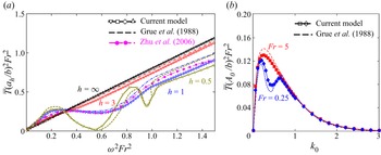
To validate the present model, we compare the thrust force of the plate with Grue et al. (Reference Grue, Mo and Palm1988) for the scenarios in which the plate undergoes periodic heaving motion close to the calm free surface without any incident wave in figure 2(a). Four submergence depths,  $h=0.5, 1,3,\infty$, are tested, while the Froude number is fixed at
 $Fr=0.25$ for all cases. The non-dimensional amplitude of heaving motion is denoted
 $a_h/b$. In addition, the numerical results of the same problem for a three-dimensional foil beneath the free surface by Zhu et al. (Reference Zhu, Liu and Yue2006) are also included. In Zhu et al. (Reference Zhu, Liu and Yue2006), the heaving motion of a thin NACA0005 foil, with a large span-to-chord length ratio 10 and a small heaving amplitude
 $a_h/b=0.05$, is simulated for the submergence depth
 $h=1$. The large span-to-chord ratio of this numerical result creates a practically two-dimensional flow field similar to the conditions examined here. The present result compares well with previous analytical and numerical results. The maximum difference for
 $h<1$ cases is less than
 $3\,\%$, while the maximum difference of
 $15\,\%$ is seen between our prediction and reported values in Grue et al. (Reference Grue, Mo and Palm1988) for high frequency and small
 $h=0.5$ cases.
(a) Dependence of thrust force on the heaving frequency of a horizontal plate below the free surface, for  $Fr=0.25$ and
 $h=0.5, 1, 3, \infty$. Dashed lines are for Grue et al. (Reference Grue, Mo and Palm1988); magenta circular symbols are the numerical prediction for Zhu, Liu & Yue (Reference Zhu, Liu and Yue2006) obtained for
 $a_h/b=0.05$, with
 $a_h$ being the heaving amplitude. The other symbols are for the current model. (b) Comparison of the thrust force for different incident wavenumbers between the current model (symbols) and Grue et al. (Reference Grue, Mo and Palm1988) (dashed lines) for a fixed plate with
 $h=1$ and
 $Fr=0.25$ and 5. Here,
 $A_0$ and
 $k_0$ are the non-dimensional amplitude and wavenumber of the incident wave.

In addition, we cross-compare our predictions with the reported values of a fixed plate exposed to the incident waves, as shown in figure 2(b). Here, the plate is kept fixed at its initial position, and the thrust forces for different incoming wavenumbers are compared to reported values in Grue et al. (Reference Grue, Mo and Palm1988). The submergence depth is  $h=1$, and
 $Fr=0.25,5$ are tested. The prediction from the current method follows closely the previously reported values, with maximum error less than
 $10\,\%$.
4. Results
In the following, we investigate how the characteristic parameters influence the vibration behaviour and energy harvesting capabilities of the piezoelectric plate energy harvester.
4.1. Effects of reduced velocity
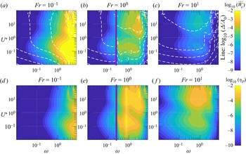
The bending rigidity of a piezoelectric plate is characterized using the non-dimensional reduced velocity  $U^*$ presented in (2.4a–d). In figures 3(a–c), the electrical power output
 $\overline {\dot {W}_e}$ and the ratio of maximum lateral deflection of the plate to the incident wave amplitude
 $\varDelta /A_0$ are plotted for a wide range of
 $10^{-2}< U^*<10^2$ and
 $10^{-2}<\omega <10$ for three representative Froude numbers:
 $Fr=0.1$ (subcritical flow),
 $Fr=1$ (critical flow), and
 $Fr=10$ (supercritical flow). Here,
 $\varDelta$ is defined as the peak-to-peak lateral deflection of the plate, defined as
 $\varDelta =y_{max}-y_{min}$, where
 $=y_{max}$ and
 $y_{min}$ are the maximum and minimum lateral positions of the plate. The immediate regions of
 $\omega \,Fr^2=\tfrac {1}{4}$ are removed from the plots with the purple line. At this condition, the radiative waves originating from the plate switch from
 $\sigma _1$ to
 $\sigma _4$ waves to include only
 $\sigma _3$ and
 $\sigma _4$ waves, hence the proposed linear solution stops being valid (Palm & Grue Reference Palm and Grue1999). All other parameters are fixed at their representative values
 $h=1.0$,
 $\alpha =0.5$,
 $\beta =1$ and
 $\tau =0$.
(a–c) The average electrical power output and lateral deflection amplitude (lines), and (b–d) energy efficiency versus  $\omega$ and
 $U^*$ for three representative values:
 $Fr=0.1,1, 10$. Other parameters are fixed at
 $\alpha =0.5$,
 $\beta =1$,
 $\tau =0$ and
 $h=1.0$. The regions close to
 $\omega \,Fr^2=\tfrac {1}{4}$ are marked with a purple line since the proposed linear solution is not valid due to abrupt changes of surface wave propagation modes (Palm & Grue Reference Palm and Grue1999).

For the subcritical flow, the output energy is impacted mainly by the wave frequency, and changes only marginally with the flexibility of the plate, represented by  $U^*$. Nonetheless, for higher frequencies, two distinct maxima are observed for all
 $Fr$ cases: one at
 $U^*>1$ resembling the flow-induced flapping mode of the plate, and the other at
 $U^*<1$ related to the cantilever resonance mode of the plate, hereafter referred to as the fluttering mode. Looking at subcritical flow with
 $Fr=0.1$ in figure 3(a), we can see that while
 $\overline {\dot {W}_e}$ decays quickly as
 $\omega$ decreases below 1, the maximum deflection of the plate is almost independent of
 $U^*$ in this range if the plate vibrates with the flapping mode. On the other hand, contour lines with similar
 $\varDelta /A_0$ have a linear trend in the
 $\log _{10}(\omega )$–
 $\log _{10}(U^*)$ plane if the plate oscillates in its fluttering mode. The exception is an isolated small region at higher
 $U^*$ and
 $\omega \approx 2$ where there is a sudden increase in the flapping amplitude and the electrical energy output. The same observation can be made across different
 $Fr$ numbers, wherein the maximum harvested energy is localized at a narrow range of frequencies and
 $U^*$. In this condition, the convective time scale of the problem and the encountered wave frequency takes a particular ratio that promotes better energy transfer from the flow to the plate.
The energy harvesting efficiencies  $\eta _P$, for
 $Fr=0.1, 1, 10$, are shown in figures 3(d–f). The energy harvesting efficiency increases with
 $\omega$ when
 $Fr$ is small and the flow is critical or subcritical. When
 $\omega \, Fr^2<\tfrac {1}{4}$, the energy harvesting efficiency shows larger sensitivity to
 $\omega$ compared to
 $U^*$. On the other hand, when
 $\omega \,Fr^2>\tfrac {1}{4}$ (the right-hand side of the purple line of
 $Fr=1$ cases, and the entire region of
 $Fr=10$ cases in figure 3b),
 $\eta _P$ is affected by both
 $U^*$ and
 $\omega$. In this case, only one new surface wave
 $\sigma _2$ will be generated in addition to the incident head wave
 $\sigma _4$, and both of these waves propagate downstream. The incoming wave transmits partially to the electrical energy, while the rest of the energy propagates in the downstream direction as new types of waves.
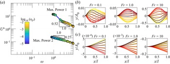
Figure 4(a) shows the locations of the two highest values of  $\eta _P$ in the
 $\omega$–
 $U^*$ plane for different
 $Fr$ numbers. The first branch is located at high
 $U^*>1$ values, and the second branch is observed at
 $U^*<1$. The highest achievable
 $\eta _P$ is always observed for higher
 $Fr$ cases, while its magnitude along both branches remains close. The position of the optimal case in the first branch follows a power law with exponent
 $\approx -0.52$, and shifts to lower
 $U^*$ and higher
 $\omega$ regimes with the decrease of
 $Fr$. The changes along the second branch are less dependent on
 $U^*$, with power-law exponent
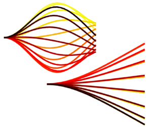
 $-0.27$. The plate undergoes different modes of vibration along each of these branches. The plate exhibits a classical travel wave deflection pattern reminiscent of the flag flapping problem along the first branch. Yet the plate vibrates at much smaller
 $U^*$ compared to that associated with the fluttering instability of light flags (Alben Reference Alben2008a). In this case, with an increase of
 $Fr$, the place of maximum lateral deflection is relocated along the length while the vibration amplitude reduces (figure 4b). On the other hand, the optimal cases along the other branch consistently vibrate in their fluttering modes, as shown in figure 4(c). In this case, the interaction between the first natural frequency of the immersed plate and the frequency of the propagating surface wave increases the oscillation amplitude, and consequently results in a higher level of harvested energy.
(a) The locations of the most energy efficient conditions in  $\omega - U^*$ parametric space with the changes of
 $Fr$. (b) Snapshot of the plate deflection over one cycle along the first branch (flapping case), with time instances marked from light to dark colour for a unit incoming wave amplitude. (c) Mode of flutter along the second branch.

The results suggest that one can practically change the plate length to attain maximum energy harvesting efficiency in two distinct response modes, flapping and cantilever fluttering modes. In particular, from the definitions of non-dimensional parameters, we can show that  $U^* \propto b^{3/2}$,
 $\omega \propto b^{-1}$ and
 $Fr \propto b^{-1/2}$, and therefore depending on the flow speed and structural parameters, the plate length can be controlled to place the system on the first optimal branch. Otherwise, the system can also be switched to the cantilever model to maintain maximum energy harvesting efficiency. Also, when the incoming wave spectrum is broadband, the cantilever fluttering mode will continue delivering maximum attainable energy. On the other hand, to benefit from the flapping mode, it is necessary to perform a complex control of
 $U^*$, perhaps by adjusting the flow velocity or, equivalently, the advancement speed of the plate.
4.2. Effects of Froude number
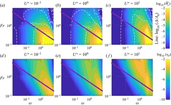
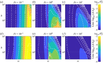
The interaction of the surface wave and the submerged plate is highly dependent on the Froude number  $Fr$. Figure 5 compares
 $\overline {\dot {W}_e}$ and
 $\varDelta /A_0$ as functions of
 $Fr$ and
 $\omega$ for three representative reduced velocities,
 $0.1$,
 $1$ and
 $10$, selected from the results discussed in the previous subsection. All other parameters are fixed at their representative values
 $\alpha =0.5$,
 $\beta =1$,
 $\tau =0$ and
 $h=1$. For the stiff plate (figure 5a), below the critical line of
 $\omega \, Fr^2=\tfrac {1}{4}$, the harvested energy is mainly a function of
 $\omega$, while for the cases above the critical line, the harvested energy is primarily a function of
 $Fr$. In this case, the plate is actuated in its cantilever fluttering mode. Vibration amplitude follows a trend similar to that of
 $\overline {\dot {W}_e}$. At
 $U^*=1$, the vibration mode starts switching from fluttering to flapping, and the region with higher
 $\overline {\dot {W}_e}$ extends to lower
 $\omega$ and higher
 $Fr$ cases (figure 5b).
Dependency of (a–c)  $\overline {\dot {W}_e}$ and
 $\varDelta /A_0$, and (d–f)
 $\eta _P$, versus
 $\omega$ and
 $Fr$ for three representative
 $U^*$ values,
 $0.1, 1, 10$. Other parameters are fixed at
 $\alpha =0.5$,
 $\beta =1$,
 $\tau =0$ and
 $h=1$.

For the very flexible plate with  $U^*=10$ shown in figure 5(c), both
 $\overline {\dot {W}_e}$ and
 $\varDelta /A_0$ are predominantly functions of
 $\omega$, and
 $Fr$ dependency is observed only over a narrow region in the parametric space. In this case, the energy-producing region shrinks along the
 $\omega$ axis but occurs over a wider range of
 $Fr$ values. The vibration mode comprises travelling flapping modes with one, two or three nodes along the plate length.
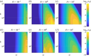
The variations of  $\eta _P$ with
 $\omega$ and
 $Fr$ are shown in figure 5(d–f). For lower
 $U^*$ cases, different from
 $\overline {\dot {W}_e}$, the region with large energy harvesting efficiency
 $\eta _P$ extends to higher
 $Fr$ ranges where the plate converts a higher percentage of the incoming wave to electrical energy.
A good correlation is identified between the amplitude of vibration and  $\eta _P$. It is observed that the highest efficiency in these cases is related directly to the amplitude of the fluttering mode, and the highest efficiency could be found over a range of
 $\omega$ just before the dominant vibration mode switching from flapping to fluttering mode. This trend changes at larger reduced velocities, where the highest efficiency is concentrated at a narrow band of
 $\omega$. The region with high
 $\eta _P$ and
 $\overline {\dot {W}_e}$ coincides at
 $\omega \approx 3$, with much lower dependency on
 $Fr$. It is found that for flexible plates, the wave cannot actuate the first fluttering mode due to a large mismatch between the natural frequencies of the plate and the incoming wave, and instead triggers and amplifies the flapping response of the plate. As a result, the plate harvests simultaneously the energy from the wave and current, and reaches much higher
 $\eta _P$.
4.3. Effects of submergence depth
The plate's submergence depth changes its receptivity to the waves. Figure 6 shows the dependency of  $\overline {\dot {W}_e}$ and
 $\varDelta$ with the submergence depth and the wave frequency for subcritical, critical and supercritical conditions. Other parameters are fixed at their reference values. For subcritical conditions, the results are almost independent of the submergence depth if
 $h<2$, equivalently when the submergence of the plate is less than its length. The same behaviour is observed for all
 $U^*$ cases. The deviation is only for minimal submergence depth where the region with high
 $\overline {\dot {W}_e}$ extends to lower
 $\omega$ ranges. In contrast, a larger dependency on the submergence depth can be found for critical and supercritical flows. For these cases, the power output shows a higher decay with depth for less flexible plates than more flexible ones. This is due to a change in the energy harvesting mechanism from wave-induced fluttering motion in stiff plates to wave-triggering flapping motion in flexible plates. A flexible plate with flapping motion has a larger oscillation amplitude, and as a result, the combination of wave actuation and flow-induced flapping results in a higher amount of harvested energy, despite the wave energy itself decaying with submergence depth. Yet the benefit of the flapping motion declines quickly with an increase of
 $Fr$, as the available wave energy weakens very fast with the depth.
Dependency of the average electrical power output and maximum plate deflection on the submergence depth  $h$ for different incoming wave frequencies
 $\omega$ and selected
 $Fr$: (a–c)
 $U^*=0.1$, and (d–f)
 $U^*=10$. The electrical parameters are fixed at the base values
 $\alpha =0.5$,
 $\beta =1$,
 $\tau =0$.

The results suggest that the flapping mode reaches the highest energy production if the plate is placed at  $h<1$ (half of the plate's length) in subcritical and critical conditions. The energy extraction efficiency plots depicted in figure 7 demonstrate that the highest energy efficiency throughout the depth occurs when the system operates under near-critical conditions and exhibits flapping mode vibration. The maximum attainable
 $\eta _P$ is smaller for stiffer plates, and concentrates near the free surface for higher
 $Fr$ conditions. In practice, these optimal conditions can be achieved with longer plates or faster incoming flow; in both cases, it is beneficial to place the plate near the free surface.
Similar to figure 6, except that it shows the contour of  $\eta _P$.

4.4. Impact of electrical parameters
The coupling between a piezoelectric plate and a resonant circuit could substantially affect the energy harvesting performance of the piezoelectric flag Xia et al. (Reference Xia, Michelin and Doaré2015). These effects are related to  $\alpha$, the coupling coefficient, as well as
 $\beta$ and
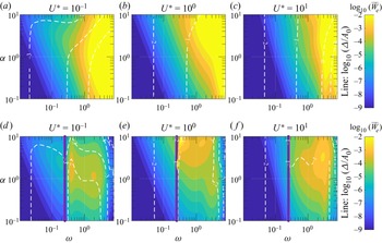
 $\tau$, the resistive and inductive properties of the electrical circuit. Figure 8 shows how electrical power output and the maximum plate deflection change with
 $\omega$ across a wide range of the electromechanical coupling parameter
 $\alpha$. The other values are fixed at their nominal values. While
 $\alpha <0.5$ is expected in conventional piezoelectric materials, higher values can be achieved in multi-segmented systems such as M4 and Pelamis with conventional mechanical energy capturing derives. It is found that electrical power output is affected mainly by the wave frequency at low
 $Fr$ flow conditions and, to a much less degree, is dependent on
 $\alpha$ (figures 8a–c). The central role of having larger
 $\alpha$ is to expand the energetic range to smaller
 $\omega$ while the energy level remains similar. The most energetic condition here is associated with stiffer plates and higher frequencies.
The effect of electromechanical coupling coefficient  $\alpha$ on the average power output and plate's lateral deflection for three representative values
 $U^*=0.1,1,10$ in (a–c) the subcritical condition with
 $Fr=0.1$, and (d–e) the critical condition with
 $Fr=1$. Here,
 $h=1.0$,
 $\beta =1$ and
 $\tau =0$.

On the other hand, the electrical power output is highly dependent on  $\alpha$ for higher
 $Fr$ cases when the plate is in the supercritical condition (right of the purple line in figures 8d–f). Here, the power output increases rapidly with
 $\alpha$, and attains its maximum values at
 $\alpha \approx 3$. However, the maximum energy output level is less than the value observed in the subcritical condition. The maximum deflection of the plate is almost independent of the
 $\alpha$ values, except for certain conditions of large
 $\alpha$ and stiff plates (figure 8a) where the large electromechanical coupling results in higher effective bending stiffness and reduction of the wave-induced vibration amplitude.
The effects of resistive and inductive properties of the plate, quantified with  $\beta$ and
 $\tau$, are shown in figure 9 for different
 $U^*$ values. In the following discussion, we focus specifically on
 $Fr=0.1$,
 $h=1$ and
 $\alpha =0.5$ to represent the energetic condition of figure 8. Two distinct
 $\omega$ values, 1 and 10, are tested, where it is found that the electric inductance can enhance the output power over a narrow range
 $\tau \omega \approx 1$. Over this range, there is a destabilizing effect from the inductance, and as a result, the plate flutters with a higher amplitude. This trend is intact across different
 $U^*$, suggesting that the inductive properties can merely be adjusted based on the wave frequency, independent of the plate flexibility, to reach a better energy harvester. The very large
 $\tau$ limit acts similarly to a short circuit and results in minimal effective coupling between electrical and mechanical fields. Consequently, the electric power output approaches zero regardless of
 $\beta$ for
 $\tau \gg \omega$. On the other hand, there is no inductance destabilization effect in small
 $\tau \ll \omega$ regimes, and the electric circuit is purely resistive. In this case, the output power is just a function of
 $\beta$ and reaches its maximum value when
 $\beta \omega \approx 1$.
Dependency of the average electrical power output to inductive and resistive properties of the plate for (a)  $\omega =1$ and (b)
 $\omega =10$. Here,
 $Fr=10^{-1}$,
 $h=1.0$ and
 $\alpha =0.5$, selected based on results in figure 8.

5. Conclusion
This work explores the energy production from a two-dimensional electromechanical flexible plate placed in the proximity of a free surface and exposed to incident travelling gravity waves and incoming current. The model represents a range of multi-segmented hybrid current/wave energy harvesting devices. In order to capture the interaction between the body, wake, and incident, diffracted and radiated gravity waves, a Green's function of a moving vortex near the free surface in inviscid flow is utilized. Through this theoretical model, we identified the optimal conditions for energy production, and examined the predominant vibration modes of flexible plates situated near the free surface.
Two distinct conditions with maximum energy production levels are identified: one is associated with the cantilever fluttering mode of the plate, and the other is very similar to the flow-induced flapping motion of the plate. The study demonstrates that the optimal energy production regimes exhibit similar trends and are influenced by changes in the Froude number. However, these energetic conditions occur at different non-dimensional flexibility values for the plate. The optimal flexibility for the cantilever fluttering mode remains relatively consistent across various incoming wave frequencies and Froude numbers. In contrast, the optimal flexibility for the flapping mode decreases progressively as the wave frequency increases. This divergent behaviour between the two modes provides valuable insights about selecting and adjusting the mechanical parameters of hybrid wave/current energy harvesting devices.
The vibration amplitude and electrical power output are highly dependent on the Froude number. In particular, their contour plots show a distinct behaviour in the subcritical, critical and supercritical flow conditions associated with  $Fr<1$,
 $Fr=1$ and
 $Fr>1$, respectively. Moreover, the resultant surface waves from the plate presence in the flow, based on the
 $\omega \, Fr^2=\tfrac {1}{4}$ condition, determines the energy output level and efficiency of the piezoelectric plate. It is seen that the submergence depth should be smaller than the plate length to reach a good energy production level. The dependency on the submergence depth is more stringent for flow-induced vibration modes than the cantilever fluttering mode.
The role of electrical parameters is more regular and does not modify substantially the optimal energy-producing conditions. Nonetheless, a larger electromechanical coupling coefficient modifies the dynamic characteristic of the system, especially more flexible plates vibrating in their flow-induced flapping mode. It mainly broadens the frequency range corresponding to near-maximum energy production behaviour. The optimal resistive value of the electric network related to wave frequency  $\beta {\omega } \approx 1$ and the optimal electric inductance is associated with near resonance condition in the electric network, namely when
 $\tau \omega \approx 1$.
The results provided in this paper could be helpful in the estimation of the operating threshold of hybrid wave/current energy harvesting devices that resemble a piezoelectric plate. It can also be employed to adjust the system's parameters, in particular the length of the device, to reach one of the highest energy-producing conditions. The current theoretical prediction using the inviscid flow theory and linear approximation should be tested with future experiments and fully nonlinear fluid–structure interaction simulations (Vahab, Sussman & Shoele Reference Vahab, Sussman and Shoele2021). In addition, the proposed model and the dispersion relation are insufficient to explore the energy production of the system at the critical condition  $\omega \,Fr^2=\tfrac {1}{4}$, where a group of reflected and radiated waves combines into one wave with a zero group velocity and no ability to transport wave energy. It would be an interesting extension of this study to explore theoretically energy production under this condition.
The predictions from the current linear model suggest that with current piezoelectric materials, the energy efficiency of the device is less than  $5\,\%$, much smaller than other conventional hydrokinetic energy harvesters (Drew, Plummer & Sahinkaya Reference Drew, Plummer and Sahinkaya2009). It is observed that with better-engineered electromechanical converters, and larger
 $\alpha$ coefficient and with the use of the inductive elements in the electrical conversion unit, the energy efficiency of the device can be much improved and becomes close to
 $40\,\%$. The flexible piezoelectric plates can also be employed as unsteady thrust-producing devices if they are attached to the side of a boat or ship and undergo combined plunge and pitch motions (Grue et al. Reference Grue, Mo and Palm1988; Belibassakis & Politis Reference Belibassakis and Politis2013). In addition, these types of energy converters have a unique property that they can be deployed or collected easily depending on the sea condition. The current model can be employed to determine the performance of hybrid wave/current energy harvesters as both the thrust-generating and energy-producing devices in these conditions. The three-dimensional effects of finite-width plates could also modify wave diffraction and energy production. Including the three-dimensional effects into the current framework is the subject of ongoing research.
Acknowledgements
The authors would like to acknowledge the Florida State University Research Computing Center and NSF ACCESS computational resources through grant no. CTS200043 on which these simulations were carried out.
Funding
This work is partially supported by NSF grant CBET-1943810.
Declaration of interests
The author reports no conflict of interest.
Author contributions
K.S. derived the theory, performed the analysis and wrote the paper.
Appendix A
In this appendix, we assume that all variables are dimensional and we derive the most general equation of the system, assuming inviscid irrotational two-dimensional flow with  $y=0$ placed at the air–sea interface pointing upwards. The velocity
 $\boldsymbol {u}$ is expressed based on the gradient of a scalar potential
 $\varPhi$, as
 $\boldsymbol {u}=\boldsymbol {\nabla } \varPhi$, and the conservation of mass requires that the potential satisfies Laplace's equation
 \begin{equation} \nabla^2\varPhi=0. \end{equation}
The pressure can be calculated from,
 \begin{equation} -\frac{P}{\rho}=g y+\frac{\partial \varPhi}{\partial t}+\frac{1}{2}\,|\boldsymbol{\nabla}\varPhi|^2+B(t), \end{equation}
where  $B(t)$ is an arbitrary function of
 $t$ that can be omitted by redefining
 $\varPhi$ without affecting the velocity field.
We have two types of boundaries: the air–water interface, which is also called the free surface, and the wetted surface of an impenetrable solid, which in this study is the surface of a thin piezoelectric plate. Along both surfaces, the flow can have relative motion only in the tangential direction, and the instantaneous equation of boundary conditions can be written as
 \begin{equation} F(\boldsymbol{X}(t),t)=y-\xi(x,t)=0, \end{equation}
where  $\xi$ is the vertical coordinate measured from
 $y=0$, and
 $\boldsymbol {X}(t)$ is a point on the interfaces moving with velocity
 $\boldsymbol {U}$. By taking the derivative of (A3), and with the assumption of only tangential relative motion at the interfaces (equivalently
 $\boldsymbol {U}\boldsymbol {\cdot }\boldsymbol {\nabla } F=\boldsymbol {u}\boldsymbol {\cdot }\boldsymbol {\nabla } F$), we can write the condition of moving surfaces as
 \begin{equation} \frac{\partial \xi}{\partial t}+\frac{\partial \varPhi}{\partial x}\,\frac{\partial \xi}{\partial x}= \frac{\partial \varPhi}{\partial y}. \end{equation}
Equation (A4) defines the kinematic boundary conditions on the plate surface and also on the free surface. On both boundaries, it is necessary to add the dynamic boundary condition. On the free surface, with atmospheric pressure  $P_a$, we can write
 \begin{equation} -\frac{P_a}{\rho}=g\eta +\frac{\partial \varPhi}{\partial t}+\frac{1}{2}\, |\boldsymbol{\nabla}\varPhi|^2\quad \text{on}\ y=\eta, \end{equation}
where  $\eta$ is the surface wave height. This equation can be combined with (A4), and with the assumption of
 $P_a=$ constant, we can write the dynamic condition on the free surface as
 \begin{equation} \frac{\partial^2 \varPhi}{\partial t^2} + g\,\frac{\partial \varPhi}{\partial t} + \frac{\partial \,}{\partial t}\boldsymbol{u}^2+\frac{1}{2}\,\boldsymbol{u}\boldsymbol{\cdot}\boldsymbol{\nabla} \boldsymbol{u}^2=0\quad \text{on}\ y=\eta. \end{equation}
With the presence of a current with velocity  $u_c$ along the
 $x$ axis, we can use the superposition technique and define
 $\varPhi =\varPhi _w+u_c x$, where
 $\varPhi _w$ is the velocity potential due to the surface waves, and
 $u_c x$ captures the effect of the current. To linearize the problem, we assume that certain physical scales of motion can be anticipated a priori, and define the non-dimensional quantities
 \begin{equation} \{\hat{x},\hat{y}\}=\frac{2 {\rm \pi}\{x,y\}}{\lambda}, \quad \hat{t}=\omega t, \quad \hat{\eta}=\frac{\eta}{A}, \quad \hat{\varPhi}= \frac{2 {\rm \pi}\varPhi}{A\omega \lambda}, \end{equation}
where  $\lambda$,
 $\omega$ and
 $A$ are the typical values of wavelength, frequency and free-surface amplitude, respectively. We can rewrite (A1), (A3) and (A5) based on
 $\hat {\varPhi }_w$ as
 $$\begin{gather} \nabla^2\hat{\varPhi}_w=0, \end{gather}$$
 $$\begin{gather}\frac{\partial \hat{\xi}}{\partial \hat{t}}+u_c\,\frac{\partial \hat{\eta}}{\partial \hat{x}}+\epsilon \left(\frac{\partial \hat{\varPhi}_w}{\partial \hat{x}}\,\frac{\partial \hat{\eta}}{\partial \hat{x}} \right) = \frac{\partial \hat{\varPhi}_w}{\partial \hat{y}} \quad \text{on}\ \hat{y}=\epsilon\hat{\eta}, \end{gather}$$
 $$\begin{gather}\frac{\partial \hat{\varPhi}_w}{\partial \hat{t}} +\left(\frac{2{\rm \pi} g}{\omega^2\lambda}\right) \hat{\eta} + \frac{\epsilon}{2}\,(\hat{\boldsymbol{\nabla}}\hat{\varPhi}_w)^2={-}\frac{2{\rm \pi} P_a}{\rho A\omega^2 \lambda}\quad \text{on}\ \hat{y}=\epsilon\hat{\eta}, \end{gather}$$
where  $\epsilon =2{\rm \pi} A/\lambda$ is the wave slope. If we assume
 $\epsilon \ll 1$, then we can drive the linear equations to
 $O(\epsilon )$, which in their non-dimensional forms based on
 $u_c$ and
 $b$ will be similar to (2.8), (2.9) and (2.10).