Introduction and scope
There is no need to discuss the width of the range of applications of steels. Tool steels have better properties than ordinary steels, including higher hardness and higher resistance to deformation. There is also a belief that tool steels have higher resistance to abrasion—a belief that we have decided to verify.
There are a variety of methods of improving surface and other properties of steels, including quenching,[ Reference Bendikiene and Zvinys 1 ] severe plastic deformation,[ Reference Dobatkin, Rybalchenko, Enikeev, Tokar and Abramova 2 ] submerged metal arc welding,[ Reference Ambroza, Bendikiene and Kavaliauskiene 3 , Reference Bendikiene, Pupelis and Kavaliauskiene 4 ] laser melting,[ Reference AlMangour, Yu, Yang and Grzesiak 5 – Reference AlMangour, Grzesiak and Yang 7 ] shot peening,[ Reference AlMangour and Yang 8 – Reference Jayalakshmi, Ramachandra Bhat and Udaya Bhat 10 ] nitriding,[ Reference Muñoz Riofano, Castelitti, Canale and Totten 11 ] electrical discharge machining,[ Reference Amorim, Dalcin, Soares and Mendes 12 ] or consecutive mechanical treatments followed by nitriding.[ Reference Tobola, Brostow, Czechowski and Rusek 13 ] Thus, in earlier work we have studied turned and burnished (T–B), turned and nitrided (T–N) and turned, burnished and nitrided (T–B–N) steels of two kinds.[ Reference Tobola, Brostow, Czechowski and Rusek 13 ] In [ Reference Tobola, Brostow, Czechowski and Rusek 13 ] we have used pin-on-disk tribometry for the determination of abrasion. We have decided now to investigate the “beginning” of abrasion by scratch resistance testing,[ Reference Brostow, Kovacevic, Vrsaljko and Whitworth 14 , Reference Brostow and Hagg Lobland 15 ] including the beginning of debris formation. We expected that the acoustic signal accompanying the indenter movement will be useful.
This project started when we acquired access to the capability of ion implantation in steels, namely of helium and krypton. To our knowledge, so-called “rare gases” were never applied to tool steels before. An important advantage of He and Kr are spherical force fields—hence factors other than the atomic mass do not interfere.
Tool steels are classified as “traditional” and “advanced”. We have studied Sverker 21 steel as a representative of the former and Vanadis 6 steel made by powder metallurgy as representing the latter. Both are chromium–molybdenum–vanadium alloyed steels. Vanadis contains hard vanadium and molybdenum carbides—rather than softer chromium carbides. Recall that chromium content allows strengthening of severe plastic deformation.[ Reference Bendikiene and Zvinys 1 ] We have 11.8 wt% Cr in the Sverker steel but 6.8% in the Vanadis steel. We have 0.8% V in Sverker but 5.4% in Vanadis.
Experimental
Materials
Sverker 21 and Vanadis 6 were provided by Uddeholms AB, Hagfors, Sweden. They were subjected to heat treatments as follows: Sverker: 270 s at 1035–1040 °C, then 2 h at 530 °C, finally 2 h at 520 °C; Vanadis: 270 s at 1070 °C, 2 h at 550 °C, finally 2 h at 520 °C. Rockwell hardness C (150 kgf, 120° diamond spheroconical indenter) HRC = 60 ± 1 was thus achieved for both.
Mechanical treatments
We have applied three types of operations: grinding (G), turning (T) and turning followed by slide burnishing (T–B). Grinding alone is a known procedure for steels.[ Reference Ding, Li and Liang 16 ] Grinding was performed as follows: peripheral wheel speed v s = 16 m/s; table feed speed v f = 210 mm/min and working engagement a e = 0.01 mm. Polycrystalline cubic boron nitride (NP-DCGW11T302GA2 BC020) was used as cutting inserts for turning at the feed of 0.06 mm/rev. with the cutting speed of 100 m/min. for Sverker and 150 m/min. for Vanadis. Different speeds were applied so as to achieve comparable roughness. A diamond was used for slide burnishing with the speed of 40 m/min., feed 0.02 mm/rev. and the force of 180 N for Sverker and 160 N for Vanadis.
Ion implantation
The IBMAL facility has been described earlier[ Reference Rout, Dhoubhadel, Poudel, Kummari, Pandey, Deoli, Lakshantha, Mulware, Baxley, Manuel, Pacheco, Szilasi, Weathers, Reinert, Glass, Duggan and McDaniel 17 ] and used in a variety of applications.[ Reference Reyes, Camacho, Camacho, Mayorga, Weathers, Salamo, Wang and Neogi 18 ] Each of our specimens was subjected in turn to focused 2.5 and 1.5 MeV ion beams of helium and krypton, respectively. The specimens were irradiated a few times with fluences of 1015 ions/cm2.
Scratch testing
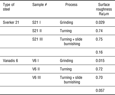
The instantaneous depth at the time the indenter “attacks” a given location is called the penetration depth R p, the depth after 2 min of viscoelastic recovery (healing) is the recovery depth R h. A linearly increasing force from 0.3 to 22.8 N was applied. A diamond indenter with the diameter of 0.10 µm was used. The depth resolution is ±0.5 nm according to the manufacturer (Anton Paar). The sliding speed was 5 mm/min, the distance covered 5.0 mm. During each test an acoustic signal is created along the indenter trajectory. We provide in the section “Symbols used for specimens” the values of the surface roughness before scratch testing. We recall that surface roughness decreases in tribological testing along with the sliding distance.[ Reference Hanief and Wani 19 ]
Microscopy
After scratch tests were performed, the samples were examined under a microscope which was part of the micro-scratch machine assembly. Panoramic photos were taken of each sample under each condition after scratch testing at 5× magnification.
Symbols used for specimens
Symbols used for specimens are listed in Table I.
Symbols used for specimens and surface roughness values.

Scratch testing results
Scratch testing provides the instantaneous or penetration depth R p at the time the indenter “hits” a given location on its path. Materials are known to resist deformation of any kind,[ Reference Brostow and Hagg Lobland 15 ] hence there is a period of recovery during which the bottom of the groove created by the passage of the indenter goes up. Our repetitive experiments on a variety of materials have shown that the recovery process is completed inside of 2 min; namely, the changes of the depth after 2 min are smaller than 1%. Then we move the indenter applying a very small force to determine the residual depth after recovery—also known as the healing depth R h. Such determinations are particularly important for shape memory alloys (SMAs).[ Reference Yang, Fortier, Horne, Brostow and Hagg Lobland 20 ]
Values of R p and R h are averages for a given material. One usually does three indenter runs and thus obtains the averages. To study more in detail a given groove, one can use the acoustic signal which is measured during the passage of the indenter so that a value exists for each location along the groove. Already in 1980 Wadley et al. noted that “metallurgical variables greatly affect the acoustic emission response of metals”.[ Reference Wadley, Scruby and Speake 21 ] We shall take advantage of this capability.
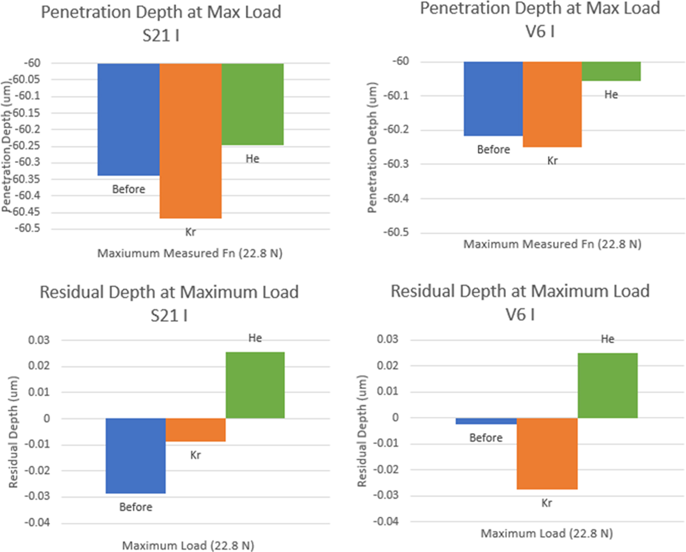
Below, Fig. 1 displays the penetration depths and residual depths at the maximal loads for one Sverker and one Vanadis steel. According to the MicroScratch Tester manufacturer Anton Paar, the depth resolution is 0.05 nm, hence it cannot be displayed in Fig. 1.
Selected scratch testing results.
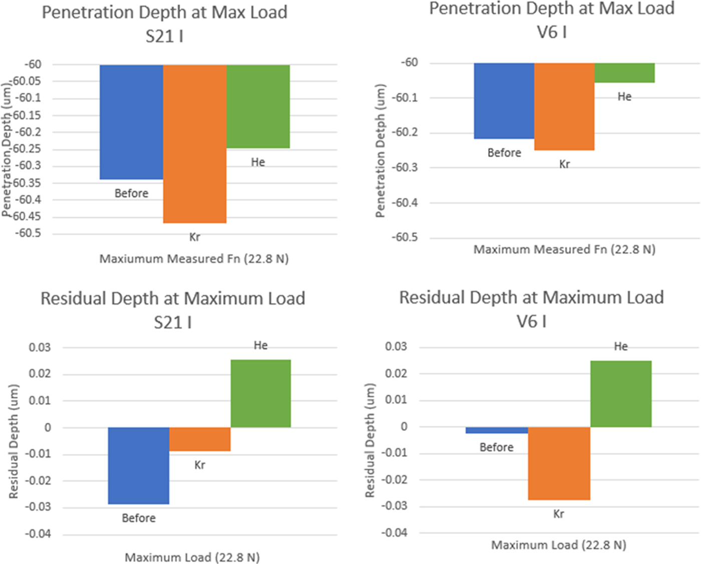
Clearly, the samples treated with helium show the lowest penetration depth whereas krypton increases that depth. Apparently, helium ions increase the resistance against scratching while larger krypton ions produce the opposite effect.
As for the residual depth, untreated Sverker steel has shown the largest value, the Vanadis steel only a small one. Here the advantage of the harder latter steel made by powder metallurgy is seen, while the softer Sverker steel does not resist the indenter “attack” well.
The differences of behavior between helium and krypton-treated samples can be explained by the differences between atomic sizes of helium (31 pm) and krypton (88 pm) ions and the respective sizes of carbon (70 pm) and iron (126 pm) atoms. Helium-treated samples have a tightly packed microstructure, contributing to lower penetration depths and positive viscoelastic recovery. Krypton-treated samples have deeper penetration depth due to internal cohesion weakening in the steels by ions larger than the carbon atoms.
We see a significant viscoelastic recovery in the softer Sverker steel, somewhat less in the Vanadis steel. Polymers are largely known for such recovery, see Chapter 19 in.[ Reference Brostow and Hagg Lobland 15 ] Such recovery has been seen also in copper pastes.[ Reference Brostow, Datashvili, McCarty and White 22 ] After the perturbations caused by the indenter, both the steels implanted with krypton ions result in final surfaces above the original ones.
Acoustic emission results
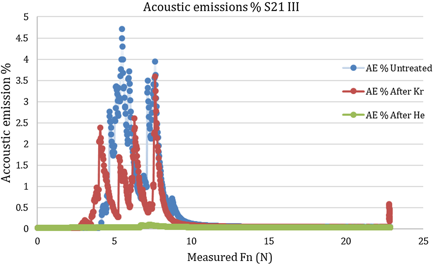
An example pertaining to the sample S21 III is shown in Fig. 2.
Representation of acoustic emissions.
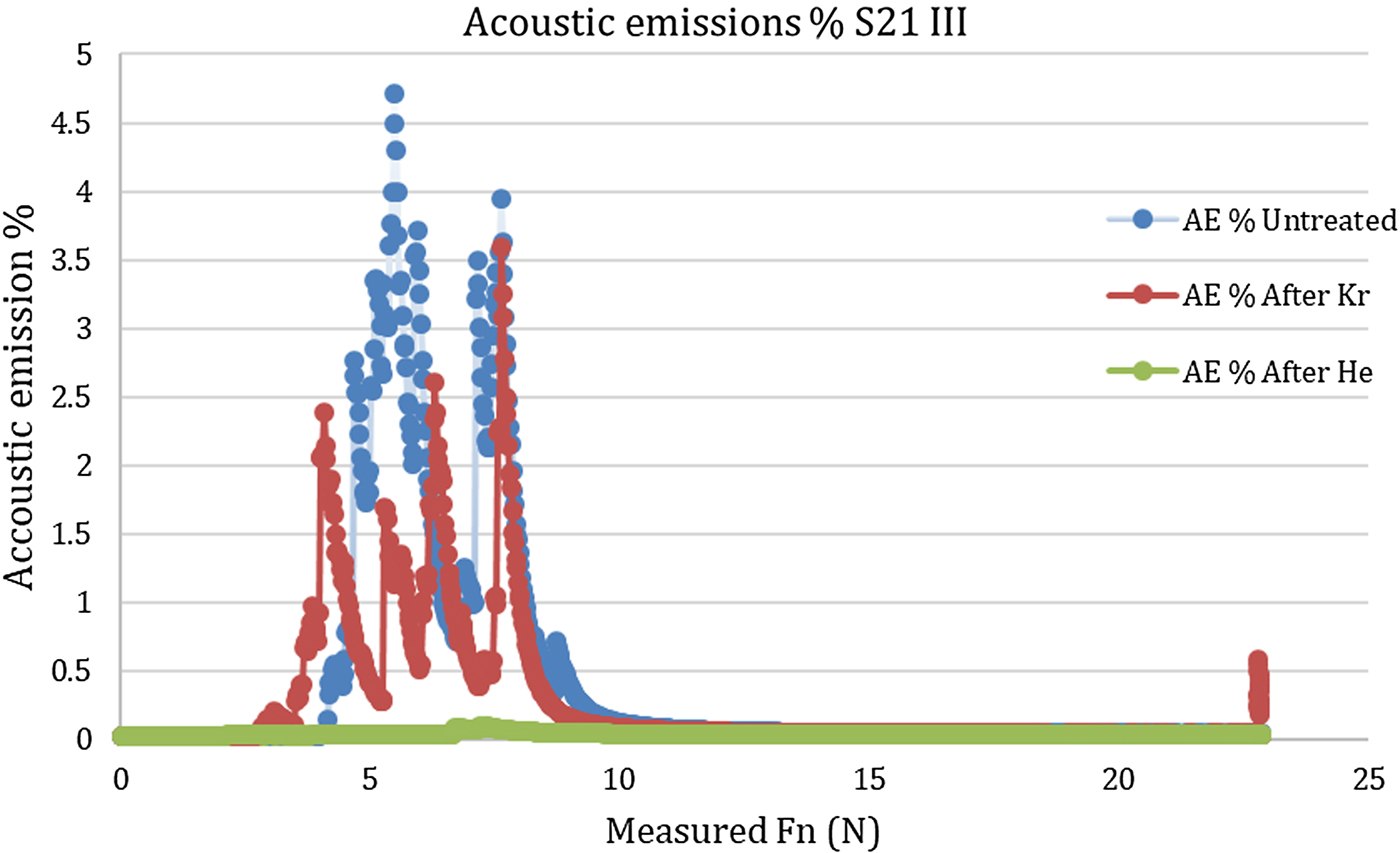
Acoustic emission is known to reflect imperfections in the surface such as microcracks—as discussed by Zhou et al.[ Reference Zhou, He and Lu 23 ] We see that krypton implantation reduces the imperfections. We further see that helium ions act even more strongly as homogenizers—almost completely eliminating the imperfections. These might be examples of material self-organization discussed by Desai and Kapral.[ Reference Desai and Kapral 24 ] A thermodynamic stability criterion tells us that materials attempt to reach equilibrium by lowering their Gibbs function G.[ Reference Brostow and Hagg Lobland 15 ] Crack formation requires increasing G since new surfaces are created. Here we have an inverse and natural process involving lowering G.
At higher force values—above 12 N or so—we see a flat acoustic signal. Apparently, the high force applied eliminates the microcracks by “flattening” them.
The effect of helium or krypton seems different from that of fillers, such as carbon or manganese used to mitigate the effects of welding in steels,[ Reference Moat, Stone, Shirzadi, Francis, Kundu, Mark, Bhadesia, Karlsson and Withers 25 ] or for that matter carbon nanotubes in elastomers.[ Reference Szymczyk 26 , Reference de Almeida Prado, Kopyniecka, Chandrasekaran, Broza, Roslaniec and Schulte 27 ] The main role of fillers is providing mechanical reinforcement rather than surface homogenization.
Microscopy observations
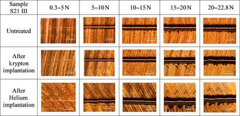
Advantages of microscopy observations of material surfaces have been extensively discussed by Michler and Balta-Calleja.[ Reference Michler and Balta-Calleja 28 ] In Fig. 3, we see images for Sverker 21 III.
Microscopy images observed for several force level ranges.

We recall first that in Fig. 2 the acoustic events take place particularly between 5 and 15 N of force. Now in Fig. 3, we see a slight scratch on the surface at 5 N, increasing in depth at 10 N, and debris forming at 15 N and beyond for each sample.
Concluding remarks
As already noted, given the importance of steels—and tool steels in particular—there is a variety of methods of improving steel surface properties.[ Reference Muñoz Riofano, Castelitti, Canale and Totten 11 – Reference Tobola, Brostow, Czechowski and Rusek 13 , Reference Antonov, Hussainova, Veinthal and Pirso 29 – Reference Staia, Pérez-Delgado, Sanchez, Castro, LeBourhis and Puchi-Cabrera 32 ] While implantation of helium and krypton ions for this purpose has not been used before, the fact that these two kinds of ions produce opposite effects was not expected.
Acknowledgments
The specimens were created and subjected to mechanical treatments under the LIDER/13/0075/L-7/15/NCBR/2016 project funded by the National Center for Research and Development of Poland, Warsaw. Helpful contributions by Jack E. Manuel and Todd Byers at IBMAL-UNT are gratefully acknowledged.