NOMENCLATURE
- δ
-
angle between R and force line of application
- DOF
-
degree of freedom
- E
-
young modulus
- F
-
force trasmitted from the actuator to the guide
- Fty
-
tensil strength (yield)
- Fty
-
tensil strength (ultimate)
- L
-
distance between actuator shaft and rib rotation hinge
- MA
-
mechanical advantage
- N
-
number of actuators
- R
-
crank dimension
- s
-
slider stroke
- X
-
slider dimension
- β
-
actuator shaft rotation
- φ
-
actuated rib morphing angle
- ν
-
poisson ratio
1.0 INTRODUCTION
Aircraft wings are equipped with control surfaces such as flaps, slats, spoilers and ailerons that provide aircraft stability and maneuverability. The use of control surfaces may be referred to as aircraft morphing due to the resulting aerofoil shape variation and increased wing surface. These traditional lift devices are described in a number of patents for use in primary flight control and load alleviation(Reference Kothera, Wereley and Woods1,2) . However, all these control surfaces have the inconvenience of intrinsic gaps and discontinuities that producing turbulence and noise. The main drawback is that they are heavy, include many mechanical parts and interfere with the wing aerodynamics.
Significant changes in drag reduction and fuel consumption can be obtained by morphing devices. Among the different potential functionalities, they may be designed to achieve chord-wise camber variations in cruise to compensate A/C weight reduction due to fuel consumption(Reference Dimino, Flauto, Diodati, Concilio and Pecora3,Reference Dimino, Flauto, Diodati, Schüller and Gratias4) during long-distance flights.
The design of an adaptive control surface such as aircraft leading or trailing edge poses significant challenges that can be overcome by a multidisciplinary approach. In Hetrick et al(Reference Hetrick, Ervin and Kota5) and Kotra et al(Reference Kota and Hetrick6), the design of an efficient structure is challenged. This includes the need for a distributed local actuation fulfilling power, weight, kinematic and reliability constraints. In patents(Reference Iannuzzo, Riccio, Russo, Calvi, Pecora, Lecce, Barbarino, Concilio and Ameduri7,Reference Pecora, Iannuzzo, Riccio, Russo, Calvi, Lecce, Barbarino, Concilio and Ameduri8) , smart actuation concepts based on innovative materials such as shape memory alloy are studied for a morphing wing flap assembly.
In order to accomplish variable wing shapes within the limits established by design constraints, both compliant structures and rigid-body concepts can be found in the literature(Reference Wang, Xu and Zhu9,Reference Friswell, Baker, Herencia, Mattioni and Weaver10) . Compliant structures allow large deformations by relying on the elastic properties of their structural components. However, their use requires a compromise between high load-carrying capacity to withstand aerodynamic loads on one hand and adequate flexibility to achieve the target shapes on the other. Compared to compliant structures, rigid-body mechanisms offer a direct solution to the morphing paradox. Actuation is carried out via a lever mechanism driven by load-bearing actuators that combine load-carrying and actuation capacities. Fewer actuators are typically required to control the morphing structure and the overall advantages derive from the reduced mass, volume, force and consumed power(Reference Ameduri, Brindisi, Tiseo, Concilio and Pecora11-Reference Pecora, Amoroso, Amendola and Concilio14).
When dealing with adaptive lifting surfaces, the level of complexity of the structural design naturally increases as a consequence of the augmented functionality of the resulting system. Specifically, an adaptive structure ensures the controlled and fully reversible transition from a baseline shape to a set of different configurations, each one characterised by different external loads and transmission paths of the internal stresses. This paper focuses on an actuation system design suitable for a morphing aileron. The study conducted in the framework of the CRIAQ MDO-505 project aims at achieving drag reduction in off-design flight points by adapting wing shape and lift distribution through the static deflection of the aileron(Reference Kammegne, Botez, Mamou, Mebarki, Koreanschi, Gabor and Grigorie15-Reference Dimino, Concilio, Schueller and Gratias17). In light of the wind-tunnel testing activity, operational aerodynamic loads have been computed firstly. Then, a single Degree of Freedom (DOF) mechanism, driven by synchronised load-bearing servo-rotary actuators, is designed to drive segmented, ‘finger-like’ adaptive ribs individually. A down-selection between different actuation system concepts driving the morphing structure is carried out. A novel actuation mechanism is hence identified for the aileron shape control as a result of numerical assessments that estimate both the stress field distribution over the actuation mechanism and the actuation authority with respect to the target aerodynamic aileron shapes.
2.0 DISTRIBUTED ACTUATION CONCEPTS FOR A MORPHING AILERON
In a morphing aircraft design concept, the actuated system stiffness, load capacity and integral volumetric requirements drive flutter, strength and aerodynamic performance. Design studies concerning aircraft flight speed, manoeuvre load factor and actuator response provide sensitivities in structural weight, aeroelastic performance, and actuator flight load distributions. Based on these considerations, the actuation mechanism is a crucial aspect of design for morphing structures because the main requirement is to accomplish variable wing shapes within the limits established by the appropriate actuation arrangement.
Hydraulic actuators are typically used for primary flight control surfaces due to the high forces required. Whereas electromechanical actuators are considered too slow and bulky to compete with hydraulics on surface actuation, the advent of digital motors has made electromechanical actuators a viable solution for controlling some secondary surfaces in which jam is not catastrophic and a hydraulic motor may be used in parallel.
The use of electro-mechanical actuators is coherent with a ‘more electric approach’ for next-generation aircraft design. Benefits are obvious: no hydraulic supply buses (easier to maintain and store without hydraulics leaks), improved torque control, and more efficiency without fluid losses and elimination of flammable fluids. In addition, it may be possible to move individual ribs either synchronously or independently to different angles (twist) to enhance aerodynamic benefits during flight. On the other hand, actuators susceptibility to jamming may represent the most important drawback.
In what follows, different actuation concepts able to transform the actuator torque into the aileron morphing deflection are assessed for a trade-off study. In detail, five actuation concepts based on either precision linear guides or cam followers are investigated to transmit actuation forces to the structure to fulfil general design targets, such as:
-
• compactness and lightness for a self-contained morphing application;
-
• morphing capability and structural robustness under the operative loads;
-
• wider stress distribution over the actuation components.
2.1 Morphing aileron architecture
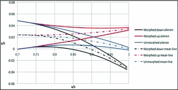
The morphing aileron design starts from the definition of aerodynamic shapes to ensure enhanced aircraft aerodynamic performance in off-design conditions. Such target shapes shall be matched by a tailored kinematics driven by an appropriate actuation system. In accordance with (78) seat regional aircraft specifications, the morphing aileron hinge axis is located at 70% of the chord. Aerodynamic requirements (delay flow transition) and structural constraints drive the aileron external contour (Fig. 1). In fact, the shapes must satisfy the following geometrical requirements:
-
• defined range for the aileron's tip deflection around the hinge axis (–7° to 7°);
-
• continuous monotonic curvature of the morphed camber lines (no changes in the sign of the slope of aileron camber);
-
• no elongations in camber line and/or skin induced by morphing.
Morphing aileron aerodynamic shapes.

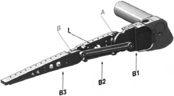
The aileron aerofoil was then approximated by a segmented rib architecture based on a finger-like layout properly tailored to enable aileron camber morphing upon actuation. Each rib (Fig. 2) was assumed to be segmented into three consecutive blocks (B1, B2 and B3) connected by means of hinges located on the aerofoil camber line (A, B). Block B1 is rigidly connected to the rest of the wing structure through a torsion tube enabling aileron rotation for roll control. Blocks B2 and B3 are free to rotate around the hinges on the camber line, thus physically turning the camber line into an articulated chain of consecutive segments. A linking rod elements (L) hinged on non-adjacent blocks forces the camber line segments to rotate according to specific gear ratios.
Morphing rib architecture: (a) blocks and links, (b) hinges.

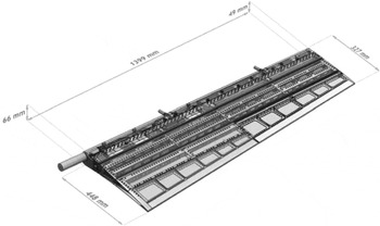
The linking element makes each rib equivalent to a single-DOF mechanism: if the rotation of any of the blocks is prevented, no change in camber/shape can be obtained; on the other hand, if an actuator moves any of the blocks, all the other blocks follow the movement accordingly. The rib mechanism therefore uses a three-segment polygonal line to approximate the camber of the aerofoil and to morph it into the desired configuration while keeping the aerofoil thickness distribution approximately unchanged. The ribs’ kinematic is transferred to the overall aileron structure by means of a multi-box arrangement (Fig. 3).
Morphing aileron structure: multi-box arrangement.

Each box of the structural arrangement is characterised by a single-cell configuration delimited along the span by homologue blocks of consecutive ribs, and along the chord by longitudinal stiffening elements (spars and/or stringers). Upon the actuation of the ribs, all the boxes are put into movement, thus changing the external shape of the aileron; if the shape change of each rib is prevented by locking the actuation chain, the multi-box structure is elastically stable under the action of external aerodynamic loads. A four-bay (five-rib) layout was considered for an overall (true-scale) span of 1.4m; AL2024-T351 alloy was used for spars, stringers and rib plates, while C50 steel was used for the ribs’ links. Off-the-shelf airworthy components were properly selected for the bearing and bushings at the hinges and coupled to torsional springs to recover any potential freeplay. A multi-module skin was considered in conformance with the multi-box segmentation; three aluminium-alloy panels were then adopted, each panel sliding over the consecutive one in an armadillo-like configuration. Airflow leakage at the skin segment interfaces was prevented through low-friction silicone seals. As one might expect, the segmented skin architecture does not significantly impact the aileron torsional stiffness and results in a slightly higher (but on the same order) conventional aileron.
The deployment kinematics use a ‘direct-drive’ actuation based on actuation arm that is rigidly connected to the B3 block in Fig. 2. This arm rotates the one-DOF-based mechanical system and transmits the actuation torque from the actuator to the adaptive rib. The control actions aim at producing small camber variation in the adaptive aileron corresponding to a rigid rotation of a plain control surface comprised between –7° and 7° during flight.
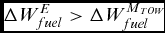
A self-contained morphing device made of links, hinges and joints to alter the inner geometry is developed with the purpose of providing a standard hinged control surface with an added functionality that may improve aircraft off-design points such as cruise or climbing. However, as with any promising technology to be integrated in aircraft, an accurate estimation of its weight loss or weight gain with respect to the conventional configuration is crucial. To date, this benefit can be only grossly computed or preliminarily assessed. On the one hand, according to Breguet's formulae, aircraft range strictly depends on aircraft aerodynamic efficiency and the ratio between the maximum take-off weight and the burned fuel weight. On the other hand, it is evident that the benefits associated with morphing will be great enough to compensate for the drawback of possible weight penalties. Therefore, in order to gain competitive advantages through morphing devices, it is necessary that:
 $$\begin{equation}
\Delta W_{fuel}^E > \Delta W_{fuel}^{{M_{TOW}}}
\end{equation}$$
Where ΔWE fuel indicates the saved fuel weight percentage due to the incremental aerodynamic efficiency for the effect of the morphing device, and ΔW MTOW fuel represents the overall aircraft structural weight penalty due to the use of the morphing aileron.
The weight of the morphing aileron designed for a 78-seat aircraft was about 25kg. Since the aircraft maximum weight is around 20tons, we see that the morphing aileron is only 5% of the entire aircraft weight. It is obvious that the weight penalty could be easily offset by a fuel savings of 3% to 6%(Reference Bolonkin and Gilyard18) provided by such a morphing technology From the manufacturing standpoint, the developed concept consists of many standard pieces and requires careful assembly procedures to support operators. This may affect its industrial applicability. Efforts are currently being pursued to simplify the design using topology optimisation methodologies to reduce the number of parts.
2.1.1 Aerodynamic loads evaluation
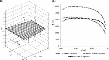
The VLM method was adopted to evaluate aerodynamic pressure distribution along the aileron corresponding with each considered flight attitude (wing angle-of-attack, flight altitude and speed) and aileron geometrical configuration. 3D flat-panels mesh was generated in correspondence of the outer wing segment; the mesh was constituted by 6 macro-panels (Fig. 4(a)) respectively representative of the outer wing root and tip portions (panels P1 and P3), of the wing box including wing leading edge (panel P2) and of the three aileron's segments (panels P4, P5 and P6). Each panel was further subdivided in a convenient number of boxes. For each flight attitude and aileron shape, the lifting pressure (P,i ) acting along each box (bi ) was calculated according to the following equation:
 $$\begin{equation}
{P_i} = q({P_{0,i}} + \alpha {P_{\alpha ,i}} + \gamma {P_{\gamma ,i}}),
\end{equation}$$
where:
-
• q = 0.5×ρ × V 2 ∞ is the dynamic pressure, ρ the air density at the flight altitude and V ∞ the airspeed;
-
• α is the wing angle of attack;
-
• P0, i is the pressure arising on bi corresponding to unitary dynamic pressure at α, γ equal to zero (aerofoil baseline camber effect);
-
• Pα , i is the pressure on bi due only to unitary adue only to unitary l baseline camber effect); at
-
• Pγ, i is the pressure on bi due only to unitary γ at unitary dynamic pressure (morphing effect).
Aerodynamic mesh (a) and pressure distribution along the aileron span (b).

Thanks to Equation (1), P0,i, Pα , i , Pγ , i are calculated only once for all the boxes and then combined according to the flight attitude parameters (α, q) and aileron morphed shape (γ) to be investigated.
The combination of α,q, and γ leading to the most significant pressure levels along aileron segments was then determined and used as design operative condition for structural sizing purpose. Span-wise pressure distributions at the design operative condition (α = 2°, q = 4,425N/m2, γ = 7°) are plotted in Fig. 4(b).
2.2 Actuation system design
Five different distributed actuation arrangements were specifically developed for the morphing aileron. The distributed actuation design consists of a number of actuators potentially enabling a redundant and fault-tolerant operation of the adaptive ribs. In this work, the following solutions were investigated:
-
• linear guide with rollers with arm linked to the first movable rib block (B2);
-
• precision linear slide with recirculating and non-recirculating ball carriages driving the second movable rib block (B3);
-
• cam follower with arm linked to the second movable rib block (B3);
-
• cylindrical ball-bearing guide mechanism driving the second movable rib block (B3).
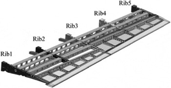
The actuation system design included the worst-case design in terms of operative loads and room available for the kinematics. For this reason, the third aileron rib (Rib 3) was considered for the structural sizing of the actuation architecture (Fig. 5). Due to their small size, Ribs 4 and 5 were considered passive and their movements slaved to Rib 3.
Aileron inner structure with rib identification.

2.2.1 Mathematical model
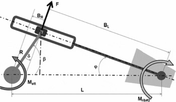
The actuation concept is an enhanced release of the oscillating glyph, already addressed in literature on a morphing trailing-edge device(Reference Dimino, Flauto, Diodati, Concilio and Pecora3). The analytical sketch of the concept is shown in Fig. 6.
Oscillating glyph connected to the second rib segment of the morphing aileron.

By assuming that the system is perfectly rigid and there is no friction among the components, the mechanical advantage of the mechanism (MA) can be written as:
 $$\begin{equation}
{\rm{MA}} = \frac{{{\rm{LOAD}}}}{{{\rm{DRIVER}}}} = \frac{{{{\rm{M}}_{{\rm{rib}}\# 2}}}}{{{{\rm{M}}_{{\rm{att}}}}}} = \frac{{{\rm{F}}{{\rm{B}}_{\rm{L}}}}}{{{\rm{F}}{{\rm{B}}_{\rm{R}}}}} = \frac{{{{\rm{B}}_{\rm{L}}}}}{{{{\rm{B}}_{\rm{R}}}}},
\end{equation}$$
where the
 ${M_{rib\# 2}}$
is the operational torque due to aerodynamic loads acting on the third rib segment, while Matt
is the actuation torque provided by the actuator in order to equilibrate the system. Furthermore, F is the force that the crank produces by means of the cursor, BL
is the force arm and BR
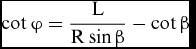
is the crank projection along the guide. From Equation (3), it follows that the mechanical advantage only depends upon the geometry of the system. In particular:
 $$\begin{equation}
\cot \varphi = \frac{{\rm{L}}}{{{\rm{R}}\sin \beta }} - \cot \beta
\end{equation}$$
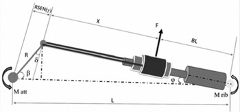
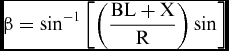
Getting previous assumptions concerning no friction-based concept, MA and the actuator rotation (β) can also be calculated for the mechanical system shown in Fig. 7. In this case, the mechanical advantage assumes the form:
 $$\begin{equation}
{\rm{MA}} = \frac{{{\rm{LOAD}}}}{{{\rm{DRIVER}}}} = \frac{{{{\rm{M}}_{{\rm{rib}}}}}}{{{{\rm{M}}_{{\rm{att}}}}}} = \frac{{{\rm{F}}{{\rm{B}}_{\rm{L}}}}}{{{\rm{FR}}\sin }} = \frac{{{{\rm{B}}_{\rm{L}}}}}{{{\rm{R}}\sin }}
\end{equation}$$
and
 $$\begin{equation}
\beta = {\sin ^{ - 1}}\left[ {\left( {\frac{{{\rm{BL}} + {\rm{X}}}}{{\rm{R}}}} \right)\sin } \right]
\end{equation}$$
Analytical scheme of the cylindrical bushing.

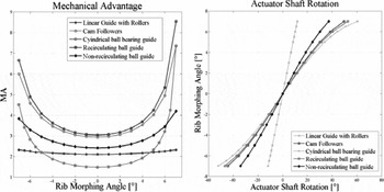
The mechanical advantage is a crucial feature which characterises the actuation concept. From Equations (2) and (4) it is possible to scale the external aerodynamic moment acting on the ribs to obtain the balancing torque. In addition, it follows that the resulting mechanical advantage drastically decreases with shorter BL. This aspect is very important because it reduces the applicability of the second concept even if the the beam excursion range angle is wider than in the previous case. Equations (3) and (5) allow calculating the actuator shaft rotation (β) needed to achieve a given morphing angle (φ) of the rib block and hence of the entire mechanism. Finally, the force F is determined to verify the stress occurring in the carriage moving into the rail that will not to exceed its design value. Therefore, the actuation rod is subjected to the simultaneous action of the force F and the external moment
 ${M_{rib\# 2}}$
, both producing bending stress. This indicates that actuation system design requires a trade-off between the mechanical advantage and the geometrical constraints limiting the actuator shaft rotation and L/R ratio.
2.2.2 Linear guide with rollers
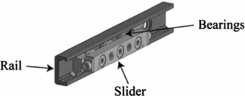
The first concept is based on the adoption of a compact linear guide characterised by a slider and a steel rail with a C-shaped cross section (Fig. 8). The slider is equipped with radial bearing rollers in alternating contact with both sides of the raceway. Radial bearings enable the guide to withstand high forces normal to the sliding line (on the order of 800N).
Main components of the linear guide with bearings, rail and slider.

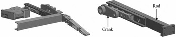
As shown in Fig. 9, such a device is fastened to the actuation steel rod of the morphing aileron driving the morphing rib kinematics through the control of B2 position. On the other side, the system transforms the actuator rotation in actuation force by means of the actuation leverage made of a crank.
Actuation system composed by linear guides with internal bearings.

2.2.3 Precision linear slide
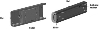
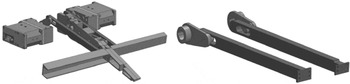
A precision linear slide with recirculating and non-recirculating ball carriages are investigated (Fig. 10) as an alternative solution to the linear guide. The former is made of a lightweight and compact linear-motion rolling guide comprising a U-shaped slip table and a stainless-steel track rail obtained by precision forming. The latter is made of a synthetic resin retainer used to host the balls while preventing their contact noise. The actuation architecture is shown in Fig. 11.
Precision linear slide with recirculating (left) and non-recirculating (right) ball carriages.

Actuation system using a precision linear slide mechanism.

2.2.4 Cam followers
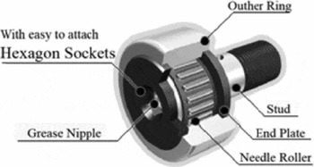
Cam followers provided with bearings have stud in which needle rollers are assembled in a thick outer ring. They exhibit a small friction coefficient and excellent rotating performances with a high radial load capacity. The inner components are shown in Fig. 12.
Cam follower.

In order to maximise the mechanical advantage (L/R increase) with respect to the previous configurations and to prevent potential mechanical plays arising during the manufacturing process, it was decided to connect the actuation rod to the rib block B3. The installation layout conceived for this solution is shown in Fig. 13.
Cam follower-based actuation system.

It should be noticed that the cam follower is positioned along the beam longitudinal axis inside the grinding surface. In order to transmit the actuator torque, the cam is in contact with the upper (morphed-down) or lower (morphed-up) sides of the grinding surface. At the same time, rotation and sliding must be ensured during deflection. This means that the beam cross-section is sized on the base of the cam diameter; however, due to high load, the contact surface between the cam and the beam may be subjected to excessive stresses because of its low thickness. On the other hand, the increased distance between the actuator shaft and the morphing pivot results in a higher mechanical advantage at the expense of a largest beam excursions during operation.
2.2.5 Ball bearing guide mechanism
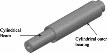
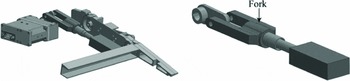
A new architecture based on a cylindrical bushing that slides along a cylindrical beam is here considered. The device is sketched in Figure 14. This concept represents a more compact solution leading to smaller (upper and lower) excursions of the actuation beam during operation but with limited mechanical advantage. The system architecture as shown in Fig. 15 details the morphed-down configuration and the kinematic components such as beam, cylindrical bearing, fork and actuator crank.
Main components of the ball bearing guide mechanism.

Ball bearing guide-based actuation system.

3.0 ACTUATION SYSTEM SELECTION
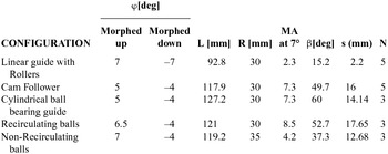
In this section, the actuation concepts are assessed in terms of mechanical advantage, excursion angle, dimensions and structural interferences. By limiting the study to a single design case concerning Rib 3, the achieved results are summarised in Table 1. Such solutions avoid any structural interference with the morphing aileron skin and spars while deployed. A comparison between the mechanical advantages vs rib morphing angle (φ) of the different architectures is reported in Fig. 16.
Comparison of investigated actuation concepts

Comparison of MA and actuator shaft rotation achieved by the investigated actuation concepts.

A full deployment up to ±7° of morphing is guaranteed by the linear guide solution with rollers, thanks to the resulting lower actuator rotation. Being linked to the second movable part (B2) of the rib, this solution may be affected by mechanical plays that may potentially arise during the manufacturing and assembly phases. Furthermore, due to the low L/R ratio, this architecture exhibits low mechanical advantage.
In the cam follower-based concept, the morphing deflection is drastically reduced to +5°/−4° due to the interference arising between the actuation rod and the upper/lower skin during morphing operation. Similarly, despite its small size, the linear guide rail architecture enables morphing aileron deflection in the range of +6.5° to −4° due to the structural interferences occurring with the upper and lower skin. Finally, the cylindrical ball-bearing guide was excluded due to the decreased mechanical advantage associated with the limited BL.
To fulfil the design target shapes in the morphed-down configuration, the non-recirculating ball carriage-based actuation concept was selected. However, such a solution is unable to reach morphing angles greater than −4° in the morphed-up configuration. Nevertheless, because it is the most promising device, such an FE model solution has been further investigated from a structural standpoint in order to be implemented in the morphing aileron.
3.1 Numerical modelling
The structural sizing of the precision linear guide with non-recirculating ball carriages was addressed by means of linear static analyses carried out in MSC-PATRAN/NASTRAN® environments. The resultant aerodynamic moment on each actuated rib was calculated from the prescribed pressure distribution (2.2) and applied to the actuation chain as concentrated load. A specific FE model was realised to validate the actuation kinematics by using concentrated load and rigid elements which transfer the load to the structure. The beam was modelled through TET10 elements(19). For each rib, the aerodynamic moment was transmitted to the structure through rigid elements (RBE2) and the reaction force acting on the linear guide was computed. The calculated force was multiplied by the crank arm to get the torque to be balanced by the actuator.
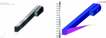
FEA results are reported below in terms of total displacements (maximum value: 2mm at beam tip) and load transmitted to the guide (239N). Since the allowable reaction force of the linear guide is equal to 232N(20), the single linear guide solution was considered structurally inadequate.
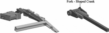
For this reason, two linear guides per each actuated beam were considered in order to improve their capability to withstand loads induced by aerodynamic pressure. The double-guide structural arrangement is depicted in Fig. 18. The actuator torque is here transmitted through a fork-shaped crank.
Beam displacement contour (left); guide reaction load of 239N (right).

Structural integration among the actuation system and the aileron with kinematic chain detail.

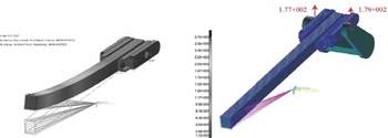
The FE results for the new actuation architecture are reported in Fig. 19; in this case the reaction forces normal at the guides result respectively equal to 177N and 179N.
Beam displacement contour (left); guide reaction loads of 177N and 179N (right).

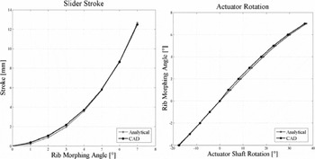
Comparison between Analytical and CAD values for actuator shaft rotation and slider stroke during aileron morphing.

The total actuation torque required to deflect the morphing aileron was then evaluated. Considering previous reaction loads, Matt is equal to 7.96Nm. The slider stroke and the actuator rotation are compared with the CAD model value and represented in two diagrams. As expected, FE simulations confirm that at the maximum morphing deflection (7°) the guide slider has a stroke of 12mm while the crank rotation is equal to 37.30.
3.2 Structural analysis of the overall system
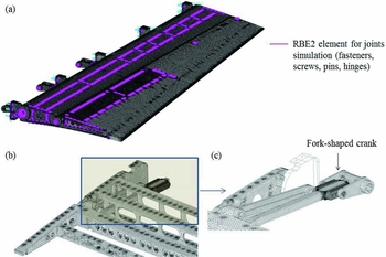
Once the optimal actuation arrangement was selected, detailed structural analyses of the overall system composed by morphing structure and actuation chains were addressed. A very accurate finite element model was then implemented for such a purpose (Fig. 21 and Table 2). All the relevant structural components (segmented ribs, spars, stringers, skin panels, actuation system leverages) were covered as well as the (screwed or riveted) joints between different parts.
FEM overview: (a) overall mesh, (b) ribs and spars, (c) detail of the actuation leverage.

FEM: mesh general data and adopted materials

Solid elements (CTETRA) were used for the mesh of the primary structure and the actuation leverage, while beam elements (CBEAM) were used for bolts, fasteners and pins.
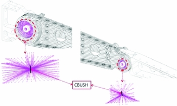
Hinges were modelled referring to the usual scheme of rigid body connections. At each of the two sides of the hinge housing, a master node was placed at the centre of the circular hole; nodes on the edge of the circular hole were then slaved to it through an RBE2 connection. Master nodes belonging to the two sides of the hinge housing were finally joined through a CBUSH element showing low stiffness about the hinge axis(19). In Fig. 22, the hinges connecting rib block 1 with 2 and rib block 2 with rib block 3 are shown.
Modelling approach for the hinged connection.

Static analysis was performed with respect to the design load condition reported in paragraph 2.1.1. Specific load fields were applied to the upper and lower skin in order to reproduce the aerodynamic pressure distribution along each segment of the aileron (Fig. 4, paragraph 2.1.1).
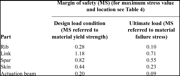
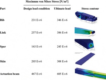
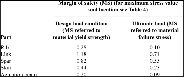
Rigid rotation of the fork-shaped crank was constrained, thus simulating a typical condition characterised by locked actuators’ shafts. Aileron rotation around hinge axis was prevented as well. Positive margins of safety (Table 3) were found with respect to local plasticisation at design loads and with respect to failure at ultimate loads (design loads multiplied by 1.5).
Margin of safety in the most stressed components
Value and location of the maximum stress in the most relevant components

No relevant torsion around the hinge axis was detected (Fig. 23); in spite of ribs and skin segmentation, the conceived multi-box layout was shown to be adequately stiff in torsion with practically no impact on roll control effectiveness. A moderate yet undesirable elastic rotation of the last aileron segment about its hinge axis was observed; instead of adding stiffness to the structure, it was considered wiser to investigate the feasibility of recovering the rotation using actuator torque. The torque required to restore the undeflected configuration was then calculated by means of a dedicated linear analysis carried out on the deformed shape with enforced motion of the actuator shafts. The obtained torque successfully resulted in compliance with the performances of several commercially available actuators; moreover, the recovery of the undeflected configurations occurred without any local increase of stress.
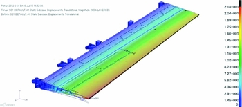
Morphing aileron elastic deflection under design loads (total displacements contour).

4.0 CONCLUSIONS
A self-contained, distributed, unshafted actuation concept is presented in this work for a smooth and gap-free chordwise camber variation morphing aileron. The mechanism, based on oscillating glyph kinematics, combines the characteristics of functionality, robustness and integratability demanded to adaptive structures. The study of the mechanical system involved the functional integration of the actuation chain into the finger-like adaptive ribs architecture. The study started from the analytical description of the actuation kinematics in order to predict actuation torque and actuators shaft rotation.
Due to the limited room available, five different actuation concepts were investigated. A trade-off study was thus carried out to reach a compromise between the high transmission ratio requirements and the small aileron deflections envisaged in the proposed morphing application. This intrinsically included any interference avoidance between morphing kinematics and the structural components such as main spar, stiffeners and adaptive skin by reducing the number of actuators. The selected architecture, based on a precision linear guide with non-recirculating ball carriages, was both analytically and numerically assessed. Concentrated loads derived from the span-wise pressure distribution were considered to simulate the operative loads acting to the actuation structure. The load transmission path from the structural layout has been applied through rigid links. The actuation kinematics was thus validated against operative loads for the most critical design case.
5.0 CONFLICT OF INTEREST
The aurhors confirm that this article content has no conflict of interest.
ACKNOWLEDGEMENTS
The authors acknowledges ETS (L'École de Technologie Supérieure), NRC (Canadian National Research Council), Bombardier Aerospace, Thales Aerospace and Alenia Aermacchi for their technical support as partners of the CRIAQ MDO-505 project. Special acknowledgements go to Professor Ruxandra Botez (ETS), coordinator of CRIAQ MDO-505 project, for defining a purpose and goals for this work.