
Introduction
Adaptation is one of the most intriguing processes in nature. Although slow, adaptation processes in all levels of hierarchy, from individual molecules to entire organisms, are an efficient way to respond to various and changing environments. During millions of years of evolution, living organisms have continuously optimized themselves to increase their chances of survival. The tremendous amount of living organisms, combined with the very specific needs of each one of them, eventually resulted in a vast range of nature-tailored biomaterials with specific properties. Those properties can be of manifold nature, including mechanical stability,[Reference Reddy and Yang1, Reference Li, Chang, Chao, Wang and Chang2] chromatic effects,[Reference Kinoshita and Yoshioka3] or hydrophobic/hydrophilic surfaces,[Reference Darmanin and Guittard4] all of which are achieved by adaptations of structural and compositional features through persistent mutation and survival of the best adapted mutant.
From the compositional perspective, the creation of hybrid organic–inorganic materials is a strategy very often observed in nature and serves for tuning the properties of materials. Thanks to biomineralization processes soft organic matrices (proteins, polysaccharides, etc.) can be blended with hard inorganic moieties (minerals, metals, etc.), providing the resulting organic–inorganic hybrid material with extraordinary properties. One of the most characteristic examples can be found in all vertebrates, the bone. Bones are tough, giving bodies a structure and protecting vulnerable organs, but at the same time they are elastic enough to compensate the stress that acts on the body upon movements or any kind of external impact. This twofold and seemingly contradictory behavior arises from the composition of the bone: an organic matrix, mainly composed of collagen, compositionally and structurally precisely intermixed with inorganic hydroxyapatite nanocrystals.[Reference Boskey5, Reference Ozawa, Hoshi and Amizuka6] Depending on the type of bone, the proportion of the components varies and so do the properties.
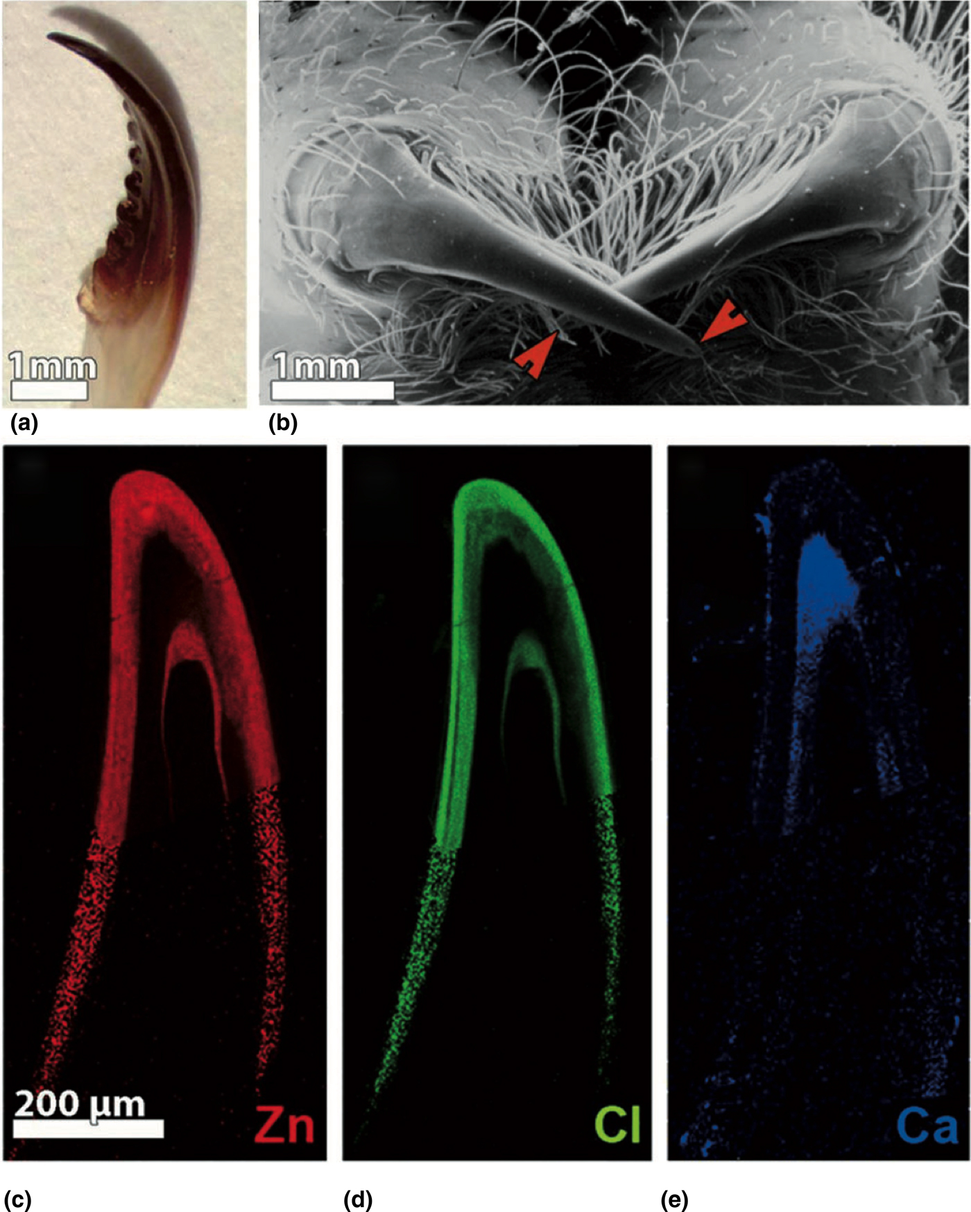
Biomineralization also plays an important role in the protection and adhesion of mollusks; the tough shell of most mollusks is composed of inorganic CaCO3 “bricks” connected by an organic “mortar,”[Reference Sumitomo, Kakisawa, Owaki and Kagawa7] and the strong adhesive mussels used to adhere to rocks consist of proteins cross-linked by metals.[Reference Muscheln and Untersuchungen8, Reference Hight and Wilker9] Broomell et al. were pioneers in demonstrating that metal ions present in the protein matrix were also critically important for the mechanical toughness of the jaw of the Nereis sea worm (Fig. 1).[Reference Broomell, Mattoni, Zok and Waite10, Reference Broomell, Zok and Waite11] Later work showed that biomineralization plays a role not only in stiffening of biomaterials,[Reference Cribb, Stewart, Huang, Truss and Noller12–Reference Politi, Priewasser, Pippel, Zaslansky, Hartmann, Siegel, Li, Barth and Fratzl15] but also in further critical properties of biomaterials,[Reference Degtyar, Harrington, Politi and Fratzl16] including self-healing[Reference Carrington and Gosline17] or adhesion.[Reference Werneke, Swann, Farquharson, Hamilton and Smith18, Reference Zhao, Sun, Stewart and Waite19]
(a) Nereis jaw; (b) spider's chelicerae fangs. These tools use metal ion cross-linking to harden the tips of their structures. The red arrows mark the tips with the venom canal. (c) Metal distribution in the spider fang. Zn is found in the tip of the fang and the external layer, co-localized with Cl (d), whereas Ca (e) is found in the most internal layer above the venom canal opening. Adapted with permission from Ref. Reference Politi, Priewasser, Pippel, Zaslansky, Hartmann, Siegel, Li, Barth and Fratzl15 (John Wiley & Sons, Inc., 2012).

The first identified synthetic hybrid material was the so-called Maya Blue, even though its fabrication was likely not consciously relying on the hybridization of inorganic and organic materials. This bright blue pigment, used by the Maya in Yucatan, consists of an organic pigment, indigo, embedded in the channels of the inorganic clay palygorskite.[Reference Van Olphen20] This special structure ensures an impressive temporal stability, thus Mayan paints maintained their bright blue appearance even after centuries. Similarly, many oil paintings from the medieval age shine and glare even now. These paints were obtained after mixing inorganic metal salts with organic fatty acids, eventually yielding bright colors. Even if the initial purpose of the mixture was to obtain paints that are easy to handle, it has been later demonstrated that the creation of a hybrid material, consisting of a metal-coordinated network of diacids,[Reference Boon, Hoogland and Keune21, Reference Keune and Boon22] was responsible for the long-term conservation of the paints.
However, it was not until 1996 when biomineralization was intentionally mimicked by Belfiore et al.[Reference Belfiore, Das and Bosse23, Reference Belfiore, Indra and Das24] After mixing two organic polymers (1,2-polybutadiene and 3,4-polyisoprene) with Pd salts in solution, they observed that the solid films obtained from the metal–polymer mixture strongly differ to pristine polymer films in their physicochemical properties. Tiny amounts of Pd (4% mol) increased the Young's modulus already by a factor of 50 and changed the solubility of the polymers significantly. They identified the strong interaction between the Pd and the polymer backbone being responsible for the changes. Thereafter, mimicking biomineralization started playing an increasingly important role in materials science.
Since then, various approaches have been attempted for the intentional incorporation of metals into organic substrates. Chen et al. developed a liquid-phase strategy to incorporate eight types of metal ions into bulk materials.[Reference Chen, Ding, Zhang, Tang, Yue and Guo25] Again, the overall mechanical properties of the modified materials were significantly improved. They also observed that the change in the mechanical properties is a function of the charge and nature of the metal ions, as well as of the functional groups available in the bulk material. More recently, Pan et al. enhanced the toughness of artificial spider silk by incorporation of TiO2 nanocrystallites into the protein matrix.[Reference Pan, Zhang, Shao, Hu, Li, Tian and Wang26] The coordination of Ti with the protein matrix resulted in an enhancement of the mechanical properties of the artificial silk. However, these modification strategies are carried out from liquid phase that imposes some major drawbacks, such as swelling of the organic substrate, remaining residual solvent, or harsh acidic/basic conditions are needed for complete solubility of some substrates.
Consequently, the work presented in 2009 by Lee et al. was a change in paradigm for the processing strategies.[Reference Lee, Pippel, Gösele, Dresbach, Qin, Chandran, Braäuniger, Hause and Knez27] In this work, the mechanical properties of spider silk were greatly enhanced by mimicking the biomineralization applying a vapor-phase technique. The infiltration of gaseous metal-containing precursors into organic substrates omits the problems associated with the use of solvents and proves adequacy and versatility for the synthesis of hybrid organic–inorganic materials.
Vapor-phase infiltration
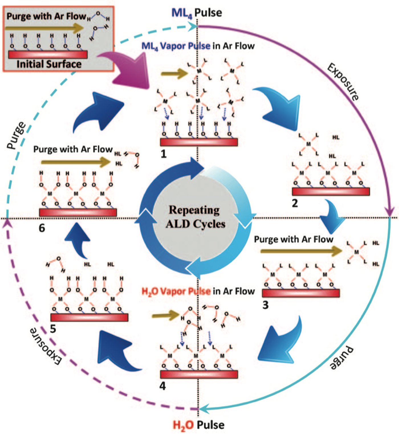
In spite of its evolution as a side effect of atomic layer deposition (ALD) in specific circumstances, vapor-phase infiltration (VPI) has demonstrated to be a really powerful technique for materials design. ALD is a self-limiting cyclic and sequential vapor-phase deposition technique to create conformal inorganic coatings, typically for application in electronic devices. Among others, ALD has the advantage of allowing an accurate control of the deposition thickness on the atomic scale, as well as the possibility to deposit certain materials even at ambient temperature. The inorganic coating is created after a surface reaction between two vaporized precursors, which are typically an organometallic chemical as metal source and a reactive counter precursor such as H2O or NH3, which act as oxygen or nitrogen sources. A typical ALD cycle (Fig. 2) consists of alternating pulses of the precursor vapors into the chamber followed by a purging step.[Reference Lee, Pippel and Knez28] As the precursors pulses are temporally separated and purging steps introduced between the individual pulses, the chemicals are never present at the same time in the chamber space. Therefore, they can only react with the molecules chemisorbed on the substrate, in this way producing a self-limiting growth of the coating. In most of the cases, ALD results in a homogeneous inorganic thin film chemically bound to the substrate surface.
Schematic representation of the basic principle of an ALD process. Reproduced with permission from Ref. Reference Lee, Pippel and Knez28 (John Wiley & Sons, Inc., 2011).

The choice of the type of substrate plays an important role in the coating process. Typically, solid inorganic substrates are chosen, which offer surface functionalities in sufficient amount and reactivity to bind the vaporized precursors rapidly and efficiently in order to speed the coating process up. However, when the substrate is a soft material (such as a polymer), the precursors will not only bind to the surface, but can also diffuse into the substrate inducing subsurface growth of inorganic material.[Reference Wilson, Grubbs and George29, Reference Knez30] This parasitic subsurface growth was initially considered a negative side effect of ALD, but it was soon discovered that the subsurface growth of inorganic material on some polymeric materials can dramatically alter some properties of the substrate. In consequence, the process was modified to optimize the diffusion of the precursors into the substrate; an exposure step was introduced between the precursor pulse and purge to allow sufficient time for the precursors to diffuse into the substrate and in this way infiltrate it. Since the potential of this technique to create hybrid materials was discovered, several research groups have simultaneously developed their own variations with different process parameters and names: multiple pulse infiltration (MPI), sequential infiltration synthesis, and sequential vapor infiltration. However, as asserted by Leng and Losego,[Reference Leng and Losego31] the atomic-scale mechanisms are identical in all the variations, so they can be grouped under a more general term, VPI.
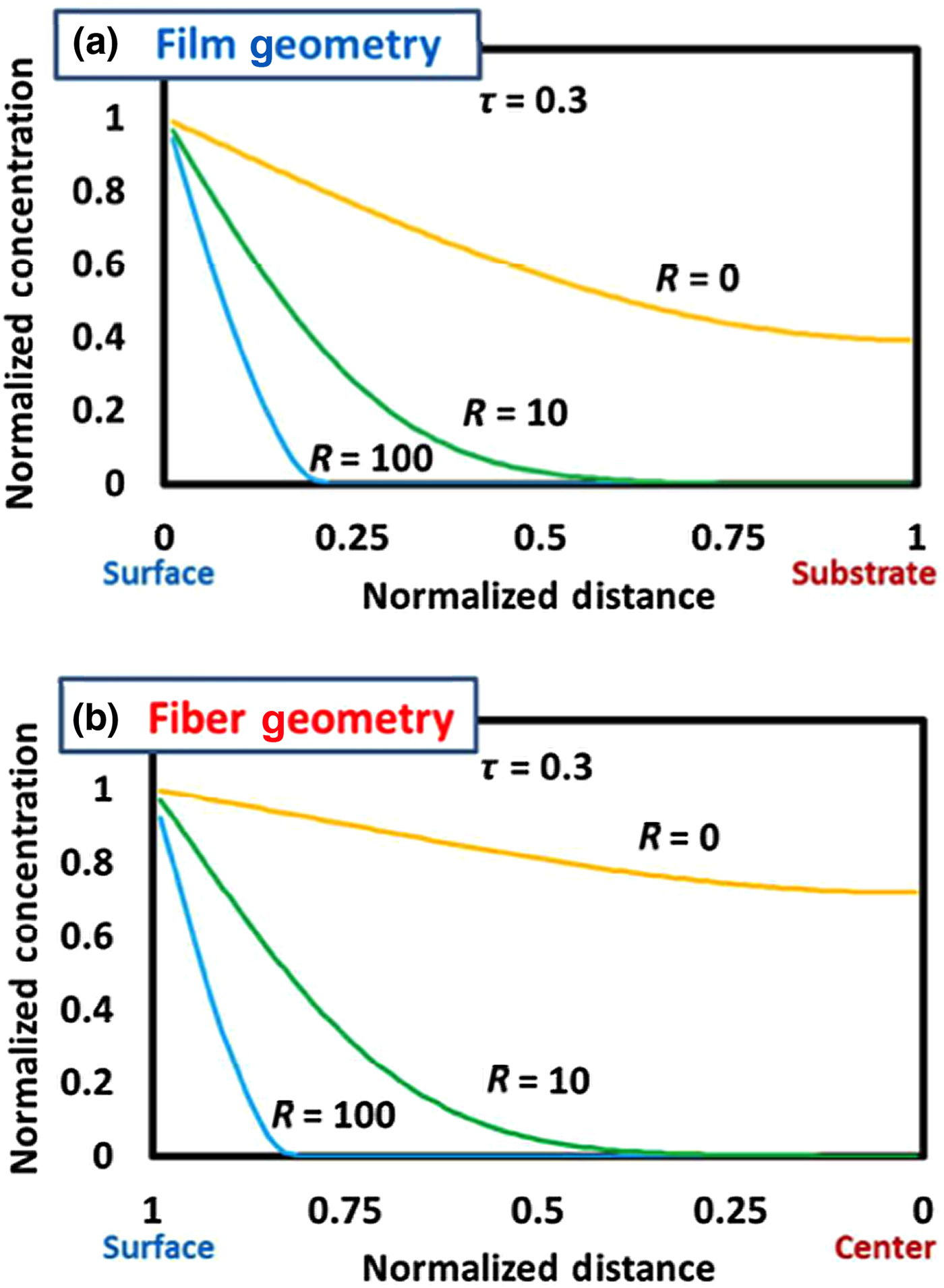
VPI has the potential to mimic biomineralization processes from the vapor phase with a great control over the final hybrid material composition.[Reference Gregorczyk and Knez32] The depth and density of the inorganic fraction into the organic substrate can be tuned by controlling some processing parameters, such as the temperature, exposure time, and number of cycles. Considering the substrate being a “fully dense” polymer, solution–diffusion is the most accurate model for describing the transport mechanism of the gaseous precursors into and through the polymer. The consideration of physical and/or chemical interactions between the diffusing molecule and the bulk material are of great importance and need to be considered in the estimation of the diffusion time. Thus, the reactivity between the precursor and the organic substrate plays an important role. Low reaction rates will lead to low hybridization levels, as the majority of the precursor molecules will be purged without reacting with the substrate. On the other hand, high reaction rates would lead to a very dense and thin inorganic layer in the uppermost subsurface area. Thus, an intermediate reaction rate is ideal; the precursor is allowed to diffuse and reach functional groups buried in deeper regions of the substrate, while the reaction will be efficient enough to prevent removal during the subsequent purging step. In addition to the precursor/polymer reactivity, the diffusion is also conditioned by the size of the precursor molecule, the free volume of the polymer, and the tortuosity of the free volume. All these variables make it difficult to predict a diffusion profile or to study the kinetics of the VPI process. A simplified mathematical model was presented by Leng and Losego[Reference Leng and Losego31] to calculate the concentration of the precursor over time and position in different substrate geometries (Fig. 3). The mild temperature and pressure conditions used in VPI enable mimicking biomineralization with a huge variety of organic substrates, both natural and synthetic. As source of the metal ions, most of the available organometallic precursors used in ALD can be applied, which is considered a beneficial circumstance as a great variety of precursors is developed for ALD. Therefore, a plethora of metal–substrate combinations has been studied with very different resulting properties and for various applications.
Calculations of normalized precursor concentration as a function of position in (a) a thin film (linear geometry) and (b) a fiber (radial geometry) for varying reactivity values of a precursor with the polymeric substrate. R = 0 equates to the purely diffusional condition with no chemical or physical interaction with the substrate. The concentration profiles refer to a normalized time τ = 0.3. Reproduced with permission from Ref. Reference Leng and Losego31 (Royal Society of Chemistry, 2017).

Mineralization of biopolymers by VPI
Being a bioinspired strategy, it is not surprising that biomaterials were the first targets for studying the mineralization through VPI. Various substrate–metal combinations have been analyzed, and the study of VPI-based mineralization of biopolymers has mainly focused on its impact on the mechanical properties.
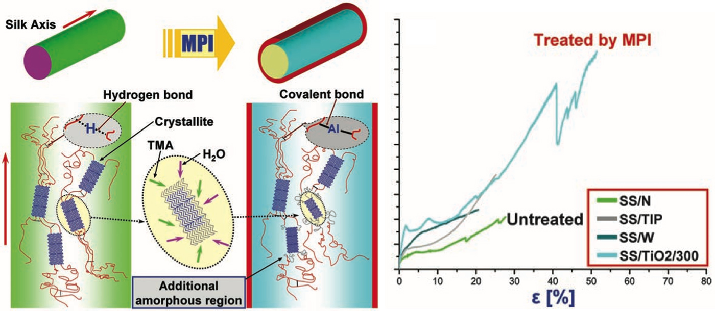
As mentioned in the Introduction section, Lee et al. were the first ones successfully demonstrating a great improvement of the mechanical properties of the materials.[Reference Lee, Pippel, Gösele, Dresbach, Qin, Chandran, Braäuniger, Hause and Knez27] They observed that the infiltration of Zn, Ti, or Al greatly increased the mechanical toughness of spider silk due to the incorporation of the metal ions into the protein matrix.[Reference Lee, Pippel, Moutanabbir, Kim, Lee and Knez33] The infiltrated ions simultaneously cross-linked the protein chains and reduced the size of the protein crystallites, altering the mechanical response of the silk (Fig. 4). A comparison of the VPI-treated samples with the same silk dipped into the same Ti precursor in liquid state showed that the great improvement of the mechanical properties could only be achieved by vapor-phase processing.
Schematic description of proposed molecular changes in the silk produced by MPI (left) and the stress–strain curves of spider silk before and after infiltration with Ti and after treatment with the individual liquid precursors (right). Reproduced with permission from Ref. Reference Lee, Pippel, Gösele, Dresbach, Qin, Chandran, Braäuniger, Hause and Knez27 (American Association for the Advancement of Science, 2009).

After the impressive results obtained from the spider silk, Lee et al. further demonstrated that the VPI process could also sustainably improve the mechanical properties of collagen membranes.[Reference Lee, Pippel, Moutanabbir, Gunkel, Thurn-albrecht and Knez34] The toughness of the collagen could even be tuned by the selection of the metal precursor with Ti showing the greatest improvement. Also here, the enhanced mechanical properties were correlated with changes in the crystal structure of the collagen resulting from the metalation.
The improvement of the mechanical properties after VPI mineralization is not always driven by changes in the crystallinity of the biomaterials. Gregorczyk et al.[Reference Gregorczyk, Pickup, Sanz, Irakulis, Rogero and Knez35] observed that infiltrating Zn or Al into cellulose fibers induced two types of reactions: cross-linking of cellulose chains through O–M–O covalent bonds and opening of the glucose rings. The impact of these individual reactions on the mechanical properties of the fibers is inverse; the cross-linking strengthens the fibers while the ring opening weakens them. Upon infiltration of low amounts of Zn, the cross-linking reaction dominated, thus the tensile strength of the cellulose fibers increased significantly. Increasing the Zn supply by means of increasing the number of infiltration cycles induced the ring opening reactions, which acted against the previous enhancement of the strength. Similar results were observed upon infiltration of Al, but with a lower impact on the mechanical properties in general.
The selectivity of the VPI process for natural materials metalation was also observed by Zhang et al.[Reference Zhang, Patil, Li, Schierhorn, Mann, Gösele and Knez36] in fibrillar nanostructures, the so-called J-aggregates, that are composed of meso-tetra(p-phenylsulfonato) porphyrin (TSPP) or meso-tetraphenylporphyrin (H2TPP). Here, the metalation of the substrates did not only depend on the metal-containing precursor, but it was also site-specific. The metalation of the porphyrins was only achieved with Zn, but not with Al and Ti. UV/Vis absorption spectra confirmed that the exposure of the samples to the zinc precursor resulted in zinc(II) complexation inside the porphyrin cavity.
Mineralization of technical polymers by VPI
Inspired by the observed impact of the metal infiltration on the properties of various biomaterials, it was a natural consequence to apply this process also to synthetic polymers and evaluate possible analogies. Given the vast amount of existing polymers and the diversity of properties and applications of them, VPI was evaluated for a plentitude of polymeric substrates. In analogy to the previous works on biopolymers, the first studies focused on the impact of the hybridization on the mechanical properties of the technical polymers. However, later works have shown that VPI is applicable for modifying both chemical and physical properties of polymers, which enable a much wider range of potential applications.
Mechanical properties
After observing the impact of the vapor-phase metal infiltration on the toughness of spider silk, Lee et al. applied the same process to polytetrafluoroethylene (PTFE).[Reference Lee, Ischenko, Pippel, Masic, Moutanabbir, Fratzl and Knez37] Even though PTFE is known for its great chemical and thermal inertness, they observed that VPI still infiltrates metal ions into the polymer. Infiltration of PTFE with Zn, Al, and Zr was shown to be possible with Zn showing the largest impact on the physical properties. A correlation of experiment and model obtained from density functional theory calculations showed that Zn–O–Zn bonds were formed that cross-linked PTFE chains, in addition to insertions of Zn into C–F bonds to form C–Zn–F at defect sites and polymer chain terminals. These modifications of the PTFE reduce the mobility and flexibility of the polymer chains, leading to embrittling of PTFE–Zn hybrid, but also in a twofold increase of the tensile strength. The most intriguing aspect of this work was that the modification of PTFE took place at 70°C only, which is contradictory to the well-known chemical stability of this polymer. In the absence of solvents, which may shield the polymer, the highly reactive precursors apparently allow for chemical reactions well below the temperature range commonly expected for a conversion of PTFE. With this work, it was demonstrated that VPI mineralization could be used to modify synthetic polymers in a similar manner as the biopolymers.
In 2013, Sun et al. analyzed the temperature dependence of the subsurface mineralization of Al2O3 in polyamide 6 (PA6)[Reference Sun, Padbury, Akyildiz, Goertz, Palmer and Jur38] in a traditional ALD process. They observed that a 120 nm thick PA6–Al2O3 hybrid layer formed at processing temperatures as low as 60°C, while negligible mineralization occurred at processing temperatures of 120°C. This hybrid layer had a direct impact on the mechanical properties of PA6–Al2O3 composite as it suppressed crack propagation by absorbing the released energy.
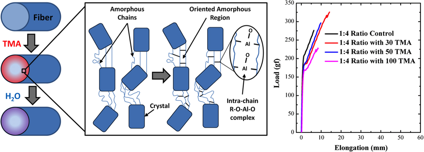
Apart from the temperature, the crystallinity of the substrate can also influence the metalation. Padbury and Jur[Reference Padbury and Jur39] studied the infiltration of Al2O3 in semicrystalline polyethylene terephthalate (PET) fibers and observed that the metalation was less effective with higher crystallinity levels of the polymer. They attribute this effect to the reduction of the accessibility of functional groups in the crystalline areas as well as to the reduction of the diffusion coefficient at the boundaries of the crystallites. Similar to the previous case, the infiltrated Al cross-linked the polymeric chains in the amorphous region by forming R–O–Al–O–R bonds (Fig. 5). With low infiltration cycle numbers, these cross-linked areas act as mechanical buffers allowing greater elongation and showing greater strength prior to failure. However, with higher infiltration cycle numbers, more Al is infiltrated augmenting the density of those mechanical buffers, which embrittle the PET fibers and reduce their strength.
Schematic representation of the infiltration of TMA into the bulk of PET fibers forming intra-chain R–O–Al–O–R complexes (left). These act as mechanical buffers within the amorphous regions of the fibers, preserving their structure and reinforcing the oriented amorphous chains, which improve the mechanical performance (right). Reproduced with permission from Ref. Reference Padbury and Jur39 (American Vacuum Society, 2015).

The change in the mechanical properties induced by VPI mineralization varies enormously from one polymer to another. McClure et al.[Reference McClure, Oldham and Parsons40] analyzed the effect of Al2O3 infiltration on the mechanical properties of the three polymers nylon 6, polypropylene (PP), and Pellethane. Pellethane showed the largest fractional increase in the Young's modulus. Even though it is not clarified in detail, they suggest the formation of new intra-chain bonds to be responsible for the stiffening of the elastomer. Nylon 6 also showed a significant increase in the modulus, which is varying as a function of the number of infiltration cycles and is accompanied by a reduction of the strain-to-failure. However, in the case of PP, even if subsurface diffusion of the precursor was confirmed by transmission electron microscopy (TEM), the chemical inertness of PP prevented significant alteration of the mechanical properties.
Hybrid organic–inorganic materials are of great technologic interest as they may bridge the materials gap between tough and brittle ceramics or metals and elastic, but mechanically weak polymers. Recently, Dusoe et al. fabricated a material with enormous elastic energy storage ability.[Reference Dusoe, Ye, Kisslinger, Stein, Lee and Nam41] This nanopatterned material combined high yield strength as it is typical for metals with a low Young's modulus as it is typical for foams. In order to obtain such combination of properties, they infiltrated lithographically patterned SU-8 photoresist nanopillars with Al2O3. As a consequence of the low chemical reactivity of the SU-8 with the organometallic precursor, the VPI process results in AlOx cluster formation inside the cross-linked polymeric matrix. These molecular clusters delay the plastic deformation of the polymer by avoiding inter-chain slipping and kink formation. This steric hindrance generates an increase in yield strength, while simultaneously the weak physical interaction between the clusters and the polymer maintains a low Young's modulus.
Besides enhancing the mechanical properties, the VPI mineralization of technical polymers has also demonstrated improvement of their stability. Azpitarte et al. studied the stability of Kevlar fibers infiltrated with ZnO upon thermal treatment and exposure to UV light.[Reference Azpitarte, Zuzuarregui, Ablat, Ruiz-Rubio, López-Ortega, Elliott and Knez42] They observed that the thermal degradation of the fibers was shifted to higher temperatures and the characteristic UV sensitivity of Kevlar was suppressed. Upon comparing ZnO-infiltrated fibers with ALD-coated fibers of the same material, it turned out that the hybrid formation and mineralization of ZnO inside Kevlar by VPI is a key for the improved stability.
Synthesis of patterned nanomaterials
The mineralization by VPI is usually applied to bulk polymeric materials. Thus, the organometallic precursor can freely diffuse and infiltrate even the entire substrate if sufficient exposure time is allowed, thus creating a random and non-patterned hybrid material or interface. However, it is also possible to introduce area selectivity in the mineralization process and in this way to create a patterned material. For the synthesis of patterned materials by VPI, three main strategies are followed: using a nanomaterial as a sacrificial template, using block copolymers with different reactivity toward the precursors, and lithography.
• Nanomaterials as sacrificial templates
The use of a sacrificial template is an efficient and easy way to create patterned nanomaterials through VPI. Even if different types of templates and processes have been described, the procedure is common for all of them. A polymer is initially infiltrated with an inorganic material by VPI. During the VPI process, the precursors will react with the organic template converting it into a hybrid organic–inorganic material. As the mineralization occurs inside the template, the morphology of the template is preserved after the hybridization. Finally, the hybrid material is calcinated and an inorganic replica of the template is obtained. Often the replica is porous, which results from the fact that the polymer initially occupied space and therefore guided the inorganic structure formation.
An example of such an approach was demonstrated by Gong et al. who used polyester fibers as templates to obtain micro/mesoporous Al2O3 monoliths after calcination.[Reference Gong, Peng, Jur, Devine, Lee and Parsons43] The obtained porous alumina monoliths reproduced the shape and dimensions of the initial template. Besides, the pore size of the inorganic monoliths could be tuned by controlling the dimensions of the repeat unit of the initial polymer.
The synthesis of patterned materials goes hand-in-hand with lithographic techniques. Thus, lithographically patterned templates have also been used for VPI processes. Nam et al. created high aspect-ratio alumina and titania nanostructures by replicating lithographically patterned SU-8 templates via VPI.[Reference Nam, Stein and Kisslinger44] The inorganic replica perfectly maintained the vertical profiles and the three-dimensional (3D) arrangement of the template. They also noticed that the infiltration with alumina was more efficient than with TiO2, which they attribute to the larger size of the Ti precursor. Similarly, Dandley et al. replicated pre-patterned polymethyl methacrylate (PMMA) templates applying VPI.[Reference Dandley, Lemaire, Zhu, Yoon, Sheet and Parsons45] They confirmed that the process was uniform and reproducible even if the nanoscale-patterned substrates had wafer-scale dimensions. They further showed that the porosity of the final inorganic replica is controllable by adjusting the calcination conditions.
Further applicable sacrificial templates include micelles. Gong et al. created porous TiO2 and alumina films by infiltrating micelles ordered within surfactant films through VPI.[Reference Gong, Kim and Parsons46] After infiltration, the organic template was not removed by calcination but by dissolving the surfactant in water. The resulting inorganic films showed a very high surface area and were greatly stable.
• Block copolymer infiltration
Among the self-assembled substrate structures, the ordered arrays of nanoscopic domains created by block copolymers are of greatest interest. The nanoscopic assembly of the domains depends on the chemistry of the constituting blocks of the polymers, so a great variety of structures and architectures can be obtained by simply tuning the compositional parameters.
Wang et al. fabricated hierarchical semiconductor nanorods that contained intriguing structural motifs, such as helices and stacked doughnuts.[Reference Wang, Qin, Berger, Yau, He, Zhang, Gösele, Knez and Steinhart47] These sophisticated structures were obtained using poly(styrene-b-2-vinylpyridine) (PS-b-P2VP) nanorods, synthesized within the nanopores of self-ordered anodic aluminum oxide, as a template for VPI. The complex template was infiltrated with ZnO and, after removal of the organic template, the ZnO replica with the hierarchical structure was obtained.
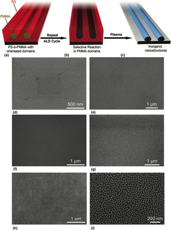
However, the most common strategy to use block copolymers for the synthesis of patterned materials through VPI is to seize the selective chemical interaction of organometallic precursors with polymers. When the individual blocks of a block copolymer show very different reactivity, the organometallic precursor will selectively interact with the most reactive block. Thus, it becomes possible to selectively infiltrate one of the fractions of the block copolymer, while the other block remains nearly in its native state. After removing the template, an inorganic replica of the nanoscopic domains of the most reactive fraction is obtained. Various alumina and titania nanostructures were obtained in this way by Peng et al. after applying VPI to poly(styrene-b-methyl methacrylate) (PS-b-PMMA) (Fig. 6).[Reference Peng, Tseng, Darling and Elam48, Reference Peng, Tseng, Darling and Elam49] They observed that the precursors diffused and infiltrated both PS and PMMA, but given the low reactivity of PS, the precursors only reacted with the PMMA domains. The dimensions of the metal oxide nanostructures obtained after template removal were tunable with the number of infiltration cycles.
Schematic representation of the process for the fabrication of nanoscopic inorganic materials by infiltration of self-assembled PS-b-PMMA thin film templates. (a) Initial template, self-assembled PS-b-PMMA films; (b) self-organized copolymer films are dried and then treated using VPI. Two key steps are involved in the process: (1) selective and self-limited coordination reaction between metal precursors and carbonyl groups in PMMA, and (2) selective and self-limited growth of materials by ALD with coordinated metal precursor as the nucleation site; (c) patterned inorganic material after the copolymer template is removed by thermal annealing or plasma treatment. (d–i) SEM images of Al2O3 patterns templated from PS-b-PMMA films on Si wafers after various numbers of Al2O3 infiltration cycles and followed by O2 plasma treatment: (d) one cycle, (e) two cycles, (f) three cycles, (g, h) six cycles, (i) ten cycles. Arrows in (a) indicate broken points along the cylinders. (f) Mixture of Al2O3 nanoposts and nanocylinders. Reproduced with permission from Ref. Reference Peng, Tseng, Darling and Elam48 (John Wiley & Sons, Inc., 2010).

The same block copolymer was selected by Kim et al. to synthesize WO3−x structures with hexagonal in-plane arrangement.[Reference Kim, Suh, Zhou, Mane, Lee, Kim, Emery, Elam, Nealey, Fenter and Fister50] They used an initial Al2O3 infiltration step to create nucleation sites for the following infiltration of W. The template was removed by oxygen plasma, which only partially oxidized the W nanostructures. A final annealing step was carried out for the complete oxidation of the nanostructures.
Another common block copolymer system used as template is PS-b-PVP. Similar to the PS-b-PMMA, only the PVP fraction is infiltrated leading to a great number of nanostructures, such as titania nanoarrays,[Reference Ishchenko, Krishnamoorthy, Valle, Guillot, Turek, Fechete and Lenoble51, Reference Yin, Xu, Wang, Yao and Wang52] alumina nanowires,[Reference Choi, Li, Black, Sweat, Wang and Gopalan53] and porous alumina films.[Reference She, Lee, Diroll, Lee, Aouadi, Shevchenko and Berman54]
• Reinforcing photoresist for lithography
Photoresists are polymers used in lithographic processes, which allow patterning of the substrate during etching processes. Mineralization of common resists for a use in lithography leads to a dramatic change in their resistance to etching. Thus, the VPI can eliminate the need of intermediate hard masks, reducing the cost and pattern fidelity losses of the lithographic process.
This approach to optimize lithography has been mainly studied by Tseng et al.[Reference Tseng, Peng, Ocola, Czaplewski, Elam and Darling55–Reference Tseng, Peng, Ocola, Elam and Darling57] They observed that infiltrating PMMA and ZEP520A resists with Al2O3 by VPI dramatically increased their resistance to plasma etching. With just few VPI cycles applied, it became possible to transfer the desired pattern into silicon. The transfer was done with high structural fidelity even for sub-100 nm features and without the need of using hard masks. Besides, the infiltration process was performed below the glass transition temperature of the resists, so its reflow was avoided.[Reference Tseng, Peng, Ocola, Czaplewski, Elam and Darling55, Reference Tseng, Peng, Ocola, Czaplewski, Elam and Darling56] This approach was also combined with the previously mentioned block copolymers. The nanodomain arrangement, in which phase-segregating block copolymers self-assemble, was used as a pattern for lithography after selectively etching away one of the copolymer blocks. However, the generally low-etch resistance of most applied polymers is an obstacle for the further development of this approach. The enhancement of the etch resistance by VPI is a pathway to make this lithography strategy applicable. Tseng et al. infiltrated PS-b-PMMA with Al2O3 and transferred the pattern into silicon, indium tin oxide, and permalloy.[Reference Tseng, Peng, Ocola, Elam and Darling57] As described in the previous section, Al2O3 selectively infiltrated PMMA. Thus, only the PMMA domains were reinforced and enabled the transfer of the pattern to the substrate.
Electronics
The incorporation of inorganic moieties into polymers undoubtedly does not only alter their mechanical, but also their electrical properties. As most of the organic polymers treated by VPI by now are electronic insulators, little attention has been paid to the impact of VPI processes on their electrical properties. However, very recent publications exploring this potential clearly demonstrate that VPI is a powerful technique for tuning polymer-based electronics.
Yu et al. focused on improving the performance of a triboelectric nanogenerator by infiltrating Al2O3 into the three different polymers: polydimethyl siloxane (PDMS), Kapton, and PMMA.[Reference Yu, Li, Wang, Gong and Wang58] The nanogenerators were composed of two polymeric films in direct contact with each other: a VPI-treated polymeric film and a pristine film of the same polymer. The metalation of the polymers resulted in an internal AlOx doping that increased the power output of the nanogenerator. As a result of AlOx clusters repelling electrons, the ability of the doped polymer to retain electrons was reduced, thus increasing the output power of the generator. The best results were obtained with doped PMMA samples. The AlOx dopant enhanced the tendency of PMMA to release electrons upon contact with the other polymer film.
A more direct way to alter the electronic properties of polymers by VPI is possible as well. Organic semiconductor polymers often require a doping process in order to create charge carriers that can delocalize along the polymer chain. The traditional way to dope such polymers consists of an oxidative treatment with strong acids, such as HCl, which protonate the polymer backbone. More recently, alternative doping strategies have been developed, among them are the application of transition metal oxides or Lewis acids as dopants. All those doping strategies are efficient in enhancing the conductivity of the polymers. However, all these processes are carried out in a liquid state, which in dependence on the anticipated application, may involve a number of drawbacks in processing or post-processing as described in the introductory part of this review. A new doping strategy based on VPI processing of polymers was developed by Wang et al. and shows an enormous breakthrough, since for the first time, doping of organic semiconductors without the use of solvents became possible. In their work, they increased the conductivity of poly(3-hexylthiophene) (P3HT) films by five orders of magnitude after infiltrating MoCl5 into the polymer.[Reference Wang, Chen, Tollan, Yang, Qin and Knez59] Moreover, the process allowed for tuning the conductivity by simply controlling the number of infiltration cycles and thus the amount of infiltrated Mo ions. The infiltrated polymer also showed exceptional long-term stability upon storage in ambient conditions.
Besides P3HT, the same group applied the VPI process to polyaniline (PANI), largely outperforming the conductivity values of PANI doped in the traditional wet-chemical way with HCl.[Reference Wang, Yang, Chen, Zhang, Qin and Knez60] In this case, both MoCl5 and SnCl4 were tested as VPI dopants with the former Lewis acid showing higher doping efficiency. The conductivity of the PANI films could also be tuned by varying the number of infiltration cycles and the samples showed great stability, in analogy to P3HT.
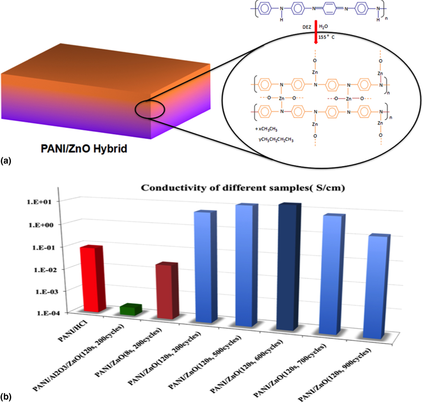
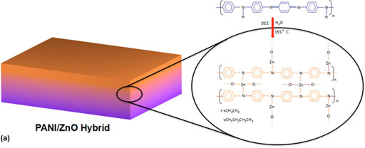
Both described processes relied on a single-precursor VPI infiltration, that is, only the metal-containing ALD precursor was supplied and allowed to diffuse and react with the polymer. A really surprising effect was discovered after the infiltration of ZnO into PANI applying a two-precursor VPI process, namely the zinc-containing precursor diethylzinc (DEZ) and water in an alternating fashion.[Reference Wang, Chen, Tollan, Yang, Beltrán, Qin and Knez61] After the infiltration, the resulting PANI–ZnO hybrid material consisted of PANI chains that were cross-linked by Zn bonds, which formed Zn–N bonds with the polymer backbone and Zn–O bonds with the supplied water molecules and the polymer (Fig. 7). Resulting from this chemical reaction, quinoid groups within the polymeric chain were turned benzenoid groups, which clearly showed that the Lewis acid was able to dope PANI. The conductivity of the resulting PANI–ZnO hybrid was as high as 18.42 S/cm. However, the conductivity rise could not be assigned to the doping of the polymer only. The unexpected high values of the conductivity pointed toward a synergy through mutual doping of both constituents, the polymer and the embedded ZnO. Namely, the infiltrated ZnO acts as a dopant for the PANI, while at the same time, through binding of Zn to the nitrogen in PANI, the infiltrated ZnO becomes nitrogen-doped.
(a) Schematic representation of a PANI substrate after doping with ZnO by VPI. The ZnO forms between the polymer chains and cross-links them in this way oxidizing the polymer backbone. The formed ZnO contributes to the conductivity synergistically and becomes doped through the N from PANI. (b) Conductivity values of the various treated PANI samples, after traditional doping with HCl (red column), after ZnO coating by ALD (green column), and after VPI doping with varying process parameters (dark green and blue columns). Reproduced with permission from Ref. Reference Wang, Chen, Tollan, Yang, Beltrán, Qin and Knez61 (American Chemical Society, 2017).

Optics
A further application field that was approached with the VPI-fabricated hybrid materials is optics. The nanopatterned materials synthesized by VPI, as described earlier in this review, were used for this purpose. With such structures, Rahman et al. fabricated an antireflective surface with an ability to more efficiently couple light into a silicon substrate.[Reference Rahman, Liu and Black62] Here, the PMMA domains of PS-b-PMMA were selectively infiltrated with Al2O3. The resulting Al2O3 replica of the PMMA domains was used as a seed structure for the growth of Ge nanoarrays. The optical properties of the nanostructured Ge surface could be tailored by controlling the generation of the initial seed layer. More recently, the synthesis of a low refractive index surface has been reported, which was synthesized exclusively through VPI.[Reference Berman, Guha, Lee, Elam, Darling and Shevchenko63] The preparation of this surface is also based on the reproduction of block copolymer domains. In contrast to the previous case, where the domains were used as a seed, in this case, the active surface was the resulting Al2O3 nanoarray, which was directly obtained by VPI of PS-b-PMMA.
Besides the templated mineralization, it was also shown that the optical properties of polymers can be altered through VPI. For example, Akyildiz et al. have shown that the photoluminescence of PET fibers can be tailored by VPI of Al2O3.[Reference Akyildiz, Lo, Dillon, Roberts, Everitt and Jur64] The photoluminescence of the amorphous PET–AlOx hybrid was tunable with the processing temperature, since the temperature is a key factor for the occurring reaction mechanism during infiltration. At lower temperatures preferably metal–organic coordination complexes were created, while chain dissociation reactions dominated at higher temperatures. The resulting hybrid fibers were photocatalytically active and promoted the growth of gold and silver nanoparticles by photoreduction in aqueous media containing the corresponding metal salts.[Reference Akyildiz, Stano, Roberts, Everitt and Jur65]
Ocola et al. studied the photoemission of ZnO-infiltrated PMMA by VPI.[Reference Ocola, Gosztola, Yanguas-Gil, Suh and Connolly66, Reference Ocola, Connolly, Gosztola, Schaller and Yanguas-Gil67] As a consequence of the hybridization, the measured photoemission properties were unusual compared with those of pure PMMA or ZnO. After an in-depth study of the occurring photoluminescence, an energy transfer between the polymer and the ZnO was confirmed. They further found that after few VPI cycles, ZnO dimers were created inside the polymer that shows features of potentially great interest for novel applications that involve quantum materials.
Also in photovoltaics, hybrid materials are gaining importance due to their high chemical stability and good control over their morphology. Thus, the new route VPI has attracted the attention of several groups investigating photovoltaic devices. Obuchovsky et al. generated a hybrid photovoltaic device by infiltrating P3HT films with ZnO via VPI.[Reference Obuchovsky, Deckman, Moshonov, Segal Peretz, Ankonina, Savenije and Frey68] The ZnO–P3HT hybrid was selectively created within the amorphous regions of the polymer film. The concentration of the infiltrated ZnO was high at the surface of the film with a concentration gradient decreasing toward the substrate. The dense inorganic layer at the surface of the polymer served as an electron-transporting layer. By tuning the process parameters, they obtained a high-performance device, which consisted of an organic–inorganic interfacial area, interconnected ZnO/P3HT networks, and a capping electron transporting layer. In a different approach, the already mentioned block copolymer templating was used for the fabrication of hybrid photovoltaics. Moshonov and Frey used poly(3-hexylthiophene)-b-poly(ethylene oxide) (P3HT-b-PEO) copolymer films that self-assemble in crystalline P3HT fibrils surrounded by amorphous PEO coronas.[Reference Moshonov and Frey69] The infiltrated ZnO selectively grew within the amorphous regions of the substrate, in this case within the PEO domains. Consequently, the thus created hybrid organic–inorganic material consisted of crystalline P3HT fibrils surrounded by the hybrid ZnO–PEO. This hybrid contained continuous interpenetrated donor–acceptor nanoscale networks. The integration of the film into single-layer hybrid photovoltaic devices demonstrated that the short circuit current density was threefold increased.
Further applications
The development of VPI is still in its infancy in various applications fields. New materials and applications are continuously being approached and interesting and innovative results are obtained, for example, the use of VPI for imaging multi-phase polymeric systems. As described earlier, the combination of block copolymers with VPI is a very fruitful approach for a plentitude of applications. For a real use of block copolymers, great control and understanding of their nanodomain structure are required. The selective infiltration of metal oxides through VPI can be used to enhance the contrast and in this way more easily image the 3D structure of these systems. Segal-Peretz et al. infiltrated Al2O3 into thin PS-b-PMMA films with various self-assembled morphologies.[Reference Segal-Peretz, Winterstein, Doxastakis, Ramírez-Hernández, Biswas, Ren, Suh, Darling, Liddle, Elam, De Pablo, Zaluzec and Nealey70] Combining TEM imaging and scanning TEM tomography, the 3D structures of the copolymers were resolved. The selective infiltration of Al2O3 into the more receptive PMMA domains “stained” those areas of the sample, enhancing the contrast between the two components.
The distribution and miscibility of polymer blends can be investigated in a similar way, as demonstrated by Obuchovsky et al.[Reference Obuchovsky, Levin, Levitsky and Frey71] They infiltrated poly(3-hexylthiophene-2,5-diyl):phenyl-C61-butyric acid methyl ester (P3HT:PCBM) films with ZnO, which allowed them to map the spatial distribution of P3HT in the polymer blend by high-resolution scanning electron microscopy. They also applied the same infiltration process to analyze the morphology and evolution of amorphous regions of P3HT when mixed with various concentrations of fullerenes.[Reference Obuchovsky, Levin, Levitsky and Frey71] By means of electron microscopy and energy-dispersive spectroscopy, they observed that the fullerenes occupy preferably amorphous domains of P3HT, thus suppressing the infiltration of ZnO. However, ICBA (a fullerene derivative with low affinity to P3HT) presented the opposite tendency; at high ICBA concentrations, it was possible to infiltrate significant amounts of ZnO. The ICBA showed a tendency to accumulate at the bottom part of the polymeric film, thus enabling an infiltration of ZnO from the top.
Another application of VPI mineralization of polymers was shown by Gong et al.[Reference Gong, Spagnola and Parsons72] A combination of VPI + ALD + MLD was used for obtaining a hydrophilic and mechanically stable finish on PDMS. PDMS is a polymer commonly used in microfluidics, but its hydrophobicity limits its use with aqueous media. Coating PDMS with a thin metal oxide film was shown to create a hydrophilic surface. However, the very different mechanical properties of PDMS and inorganic coatings commonly generate cracks in the inorganic film. Introduction of a hybrid organic–inorganic layer between the polymer and the inorganic coating acts as a mechanical buffer, compensating the mechanical stress and increasing the stability of the inorganic coating. They showed that VPI infiltration of Al2O3 into PDMS, followed by ALD alumina coating and finishing with MLD-grown alucone, a hybrid material consisting of Al interconnected with ethylene glycol, created a hydrophilic coating on PDMS that was stable for 14 days. This stability was a consequence of the smooth and crack-free coating, which hindered the diffusion of organic moieties from the polymer to the surface.
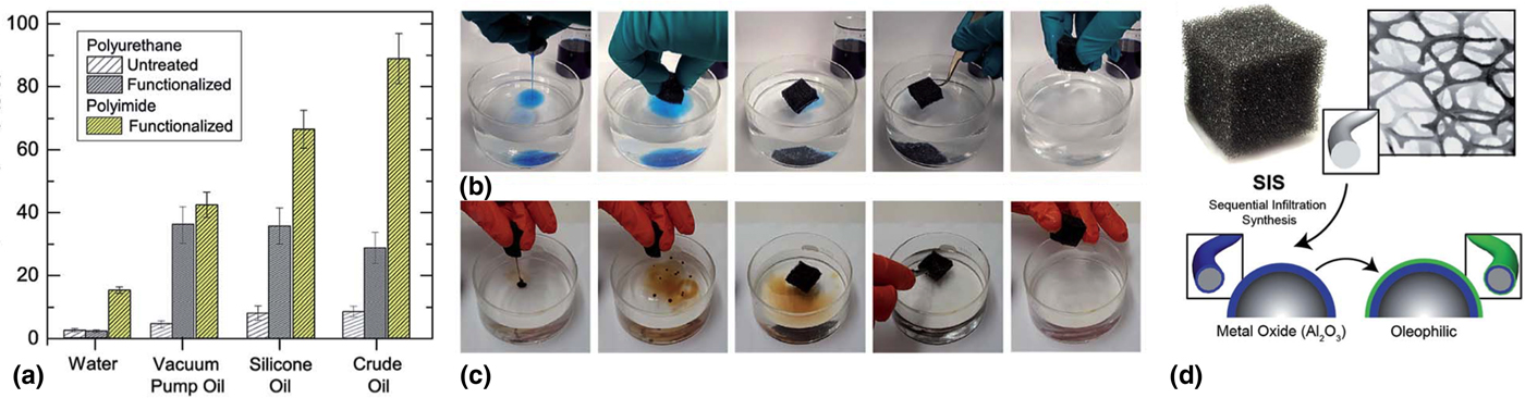
Finally, it has also been shown that VPI mineralization cannot only be applied to thin films and fibers, but also to 3D bulk materials. Aiming at improving the functionality of polymeric foams with superoleophilic compounds for oil sorption, Barry et al. processed polyurethane foams with VPI of Al2O3 (Fig. 8).[Reference Barry, Mane, Libera, Elam and Darling73] As the polyurethane foam was decomposed through the highly reactive Al precursor (TMA) and the heat evolving from the very exothermic chemical reaction of TMA with H2O, they concluded that it was necessary to adapt the VPI process to the special features of the polymeric foam. They tried three strategies to adapt the process: reducing the exposure time of the precursor, using a polymeric foam with a higher thermal stability (polyimide), and using a precursor with a less exothermic reaction with water (DEZ). All three approaches led to improved results, showing that VPI can be used for the functionalization of polymeric foams. After the VPI treatment, they grafted an oleophilic compound onto the foams. The oil sorption experiments showed that the VPI-functionalized foams were more selective and efficient in the absorption of oil.
(a) Sorption capacities are shown for untreated polyurethane foams (light gray shading), and VPI/silane-treated polyurethane (dark gray shading) and polyimide (yellow shading) foams. Sorption capacities were measured in pure solvent baths as described in the text and correspond to water, silicone oil, a hydrocarbon-based vacuum pump oil, and crude oil. Data are shown as the average taken over five different pieces of foam with error bars corresponding to standard deviations. (b) Images taken from a repetitive sorption/compression/re-sorption cycle on the surface of a water bath using dyed silicone oil. (c) Photograph of a cubical one in three piece of polyurethane foam and schematic representation of the VPI functionalization scheme to produce a metal oxide coating on the foam surface, represented in blue. In a subsequent step, a silane agent is grafted to the metal-oxide coating, rendering the foam oleophilic. Reproduced with permission from Ref. Reference Barry, Mane, Libera, Elam and Darling73 (The Royal Society of Chemistry, 2017).

Perspective
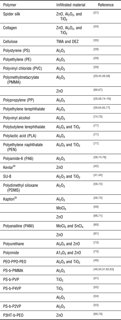
This review shows the interesting development of an initially bioinspired approach towards mineralizing inorganic materials inside biopolymers for the enhancement of mechanical properties to a truly multi-talent process, which is promising for many technologic applications. On the one hand, hybrid inorganic–organic materials can be generated by the infiltration of metal–organics from the vapor phase, some of which cannot easily be fabricated in other ways. On the other hand, the process avoids the use of solvents, which for many technologic pathways is highly demanded. Given those advantages, a plentitude of processes and material combinations has been tried with the scope to introduce novel strategies in a variety of research and development fields. Table I gives an overview of the polymer–precursor combinations that have been investigated by now. The materials and structures have proven to be suitable for advanced textile development as well as for flexible electronics, lithographic structuring, or energy conversion. Still, this development is in a very early stage and the initially developed materials are going to be further optimized. Nevertheless, those early results already promise a great application potential and will certainly serve as an inspiration for further advances in a variety of technologic areas.
Overview of the polymer substrates and VPI processes investigated by now.

The scientific perspective is also brilliant with this approach. Namely, materials science is rapidly moving toward functional materials that combine the best properties of polymers and ceramics or metals. Even though blending of polymers with inorganic nanoparticles, nanowires, or similar has already shown convincing results in terms of performance of the blends in mechanics, electronics, optics, and so on, most of those materials do not rely on a true chemical interaction of the polymeric and inorganic phase. With that respect, the materials fabricated by VPI are rather comparable with metal–organic frameworks but grown in a top-down fashion. The process is even up-scalable to large areas or amounts, but the resulting material is not as ordered on the molecular level as MOFs are. This gives a new type of polymer–inorganic blend that has yet to be understood from the scientific perspective.
Finally, considering the fact that ALD is a rapidly progressing coating technology and numerous laboratories have access to this technique, this may allow the researchers to easily perform further and new experiments, since the VPI process is largely compatible with most of the available ALD instrumentation. It may also be easily adapted to specialized high-throughput processes developed for ALD, such as fluidized bed reactors for particles, roll-to-roll reactors for continuous polymer sheets, or simply large-scale batch reactors for parallel processing of a multitude of samples. The main drawback of the technique has, however, still to be solved, the long processing time. While ALD processes are considered to be slow per se, the VPI processes require a considerably longer time to allow the diffusion of the precursors into the polymer. Here some more development will be needed from the physical perspective in order to speed up the infiltration and in this way make the processes economic.
Acknowledgments
I.A. acknowledges the Basque Government for a Ph.D. fellowship (PRE_2016_2_0022). M.K. is grateful for funding from the Spanish Ministry of Economy and Competitiveness (MINECO) within grant agreement no. MAT2016-77393-R, including FEDER funds, and the Maria de Maeztu Units of Excellence Programme—MDM-2016-0618. The authors acknowledge networking support within the COST action MP1402.