I. INTRODUCTION
With the development of engineering materials, bimetal composites have attracted extensive attention in material science owing to their unique properties and low cost.Reference Yang, Zhang, Li and Li1,Reference Abbasi, Karimi Taheri and Salehi2 Bimetal composites made of light alloys with cast iron or steel insert have been developed to reduce the weight and improve the performance of cars or other transport vehicles.Reference Durrant, Gallerneault and Cantor3 Till now, some different techniques have been applied to producing such bimetal composites, such as explosive welding, rolling bonding, diffusion bonding, extrusion, and friction stir welding.Reference Kahraman, Gulenc and Findik4–Reference Lee, Bang and Jung8 Considering the cost and practicality synthetically, however, bimetal composites fabricated via diffusion bonding possess vast potential for future development.Reference Viala, Peronnet, Barbeau, Bosselet and Bouix9,Reference Bouche, Barbier and Coulet10
To ensure fine sealability and good thermal conductivity, formation of a sound metallurgical bonding at the insert/alloy interface is necessary for bimetal composites.Reference Viala, Peronnet, Barbeau, Bosselet and Bouix9 Therefore, it is also greatly important to research the course of forming interfacial bond zone. For the interface between light alloys and gray iron or steel, previous worksReference Bouayad, Gerometta, Belkebir and Ambari11–Reference El-Mahallawy, Taha and Shoeib13 were focused on researching the intermediate layer, and the results showed that the diffusion reaction between liquid aluminum alloys and solid iron produced an intermediate layer (also called the reaction layer) at the interfacial bond zone during hot dipping. Meanwhile, the thickness of the intermediate layer mainly depends on the interdiffusion-controlled growth of the continuous phase layers. The hot-dipping time t dependence of thickness d can be expressed by the following formula:
 $$d \;\propto\; K{t^n}\quad .$$
Besides, with increasing temperature, the thickness of the intermediate layer increases. To improve the wetting of a solid insert by a liquid alloy and acquire a sound metallurgical bonding, the solid insert was immersed into the liquid Zn–Al alloy at 733 K for 10 s and subsequently dipped into the liquid GA6Z1 or GA10Z1 light alloy at 923–1023 K for 240 s as in Ref. Reference Sacerdote-Peronnet, Guiot, Bosselet, Dezellus, Rouby and Viala14.
Besides, alloy elements of aluminum alloys can affect the interfacial bond of Al/Fe bimetal composites as well. References Reference Cheng and Wang15–Reference Springer, Kostka, Payton, Raabe, Kaysser-Pyzalla and Eggeler17 presented that the addition of Si into the aluminum alloy has a great influence on the intermediate layer, which not only makes the interface morphology between the intermediate layer and the iron substrate nearly become flat from the classical tongue-shaped but also affects the growth of the intermediate layer. In the liquid/solid diffusion couples, Si decelerates the growth of η phase in the intermediate layer.Reference Cheng and Wang15–Reference Springer, Kostka, Payton, Raabe, Kaysser-Pyzalla and Eggeler17 But in the solid/semisolid diffusion couples, Si accelerates the growth of η phase in the intermediate layer.Reference Springer, Kostka, Payton, Raabe, Kaysser-Pyzalla and Eggeler17
Another important concern is the effect of Fe on the mechanical properties of the Al matrix transition layer in Al/Fe bimetal composites. In casting aluminum alloys, Fe is considered as a harmful element, since it forms the undesired intermetallic phases,Reference Cameron, Taylor and Dahle18 like the β-AlFeSi phase, with a needle-like morphology that reduces ductility and toughness.Reference Ma, Samuel, Samuel, Doty and Valtierra19 Although both the high cooling rate and the addition of Mn can modify the harmful morphology of these phases to improve the mechanical properties, but compared to the latter, the operability of the former is not very good, and the effect of the former is also limited.Reference Ma, Samuel, Samuel, Doty and Valtierra19 In the Al–Si alloys of high iron content, with increasing Mn content, the effect of Mn on modifying the morphology of the needle-like β-AlFeSi phase would be further improved.Reference Seifeddine and Svensson20 However, excess Mn may affect the mechanical properties of alloys for the formation of the new additional intermetallic phases.Reference Shabestari21 During solidification of the casting Al–Si alloy, α-Al(Fe,Mn)Si phase can arise as a product of the direct precipitation from the liquid alloys after adding Mn, but part of α-Al(Fe,Mn)Si phase have been a product of the peritectic transformationReference Tibballs, Horst and Simensen22,Reference Małgorzata, Krystyna and Jan23 :
 $${\rm{Liq}} \to {\rm{\alpha {\hscale50%-} Al}}\left( {{\rm{Fe,Mn}}} \right){\rm{Si}} + {\rm{Liq}}\quad {\rm{,}}$$
 $${\rm{Liq}} \to {\rm{\beta {\hscale50%-} Al}}\left( {{\rm{Fe,Mn}}} \right){\rm{Si}} + {\rm{Liq}}\quad {\rm{,}}$$
 $${\rm{Liq}} + {\rm{\beta {\hscale50%-} Al}}\left( {{\rm{Fe,Mn}}} \right){\rm{Si}} \to {\rm{\alpha {\hscale50%-} Al}}\left( {{\rm{Fe,Mn}}} \right){\rm{Si}}\quad {\rm{.}}$$
Due to different Mn–Fe ratios, the α-Al(Fe,Mn)Si phase is formed by different reactions.Reference Tibballs, Horst and Simensen22
Previous work could seldom provide a practical approach to achieve an integrated metallurgical bonding, and rarely investigated the effect of Mn on the interfacial bond zone. In the present work, the fluxing and hot-dipping pretreatments are used to improve the wetting of the gray iron specimens by the liquid Al–7Si alloy and achieve an integrated metallurgical bonding. Specially, a further analysis of the effect of Mn on the morphology of Al–7Si/gray iron interfacial bond zone will be carried out initially.
II. EXPERIMENTAL SECTION
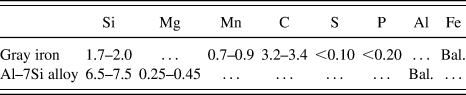
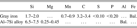
The gray iron bars (3 × 3 × 75 mm3 in size) and Al–7Si alloy materials were prepared for the present experiment. Their chemical compositions are shown in Table I. The gray iron bars were pretreated by removing grease and rust using absolute ethyl alcohol and dilute muriatic acid (30%), respectively, and they were cleaned as standby specimens using pure water.
Chemical compositions of the gray iron and Al–Si alloy materials.
The flux is a kind of mixed salt solution which contains 46% KF and 54% KCl at a concentration of 100 g/L. The fluxing operation is that the standby specimens were immersed in the flux solution for 10 min (the temperature was maintained at 353 ± 5 K) and then, removed and baked out at 423 ± 5 K for 600 s. The principles of choosing the flux are considered as followsReference Cook24:
(i) First, activate the surface of gray iron specimens, and improve the wetting of the gray iron specimens' surface by the liquid Al–7Si alloy.
(ii) Second, protect gray iron specimens from being oxidized after pretreatment.
The experimental procedure has two successive steps: the first step, immerse the gray iron specimens in liquid Al–7Si alloy at 993 ± 10 K for 120 or 300 s and then, take them out rapidly and fasten on a permanent mold preheated at 673 K; the second step, pour the fresh Al–7Si alloy into the mold at 993 ± 10 K. The five alloys with nominal Mn levels of 0, 1, 1.5, 2, and 5 wt% were prepared in an intermediate frequency furnace.
The specimens were mounted by epoxy and polished mechanically. To further analyze the interfacial bond zone, the cross-sectional microstructure of each specimen was examined using an optical microscope (OM) and a scanning electron microscope (SEM), and the phases were chemically characterized to evaluate the nature of the intermetallics using energy dispersive spectroscopy (EDS).
III. RESULTS
A. A complete metallurgical bonding formed at the Al–7Si/gray iron interface
In this study, the surface treatment process was investigated to form a complete metallurgical bonding at the Al–7Si/gray iron interface.
Figure 1 compiles representative results obtained from SEM and EDS measurements. Figure 1(a) shows a cross-sectional SEM micrograph of the specimen poured directly at 993 K. Obviously, a black gap and oxide layer was formed at the interface between Al–7Si alloy and gray iron specimen. The oxide layer mainly consisting of Al2O3 was characterized by EDS. This joint is called mechanical bonding mechanically interfitted between the Al–7Si alloy and the gray iron specimens. To form a metallurgical bonding at the Al–7Si/gray iron interface, surface treatment of gray iron specimens by hot dipping at 993 K for 300 s was applied. Obviously, a continuous intermediate layer was formed in the local region at the Al–7Si/gray iron interface, but there was also a large percentage of mechanical bonding marked with a dotted box [in Fig. 1(b)]. In addition, Fig. 1(c) shows the SEM micrograph of the specimen obtained with surface treatment by fluxing prior to hot dipping. There is a complete continuous intermediate layer marked out by the red dashed line, formed at the Al–7Si/gray iron interface, and its chemical composition change along with the black arrow is shown in Fig. 1(d). This joint is called metallurgical bonding because a chemical bond combination is formed at the interface between Al–7Si alloy and gray iron specimens. Besides, an Al matrix transition layer that consists of discontinuous iron-rich phases, eutectic silicon, and Al matrix was formed at the side of the Al–7Si alloy substrate. By comparing with Figs. 1(a)–1(c), it reveals that the specimens could form a complete metallurgical bonding layer at the Al–7Si/gray iron interface after fluxing and hot-dipping treatment.
SEM analysis of the interface between Al–7Si and gray iron in the specimen obtained with different treatments. (a) Cross-sectional micrograph of the specimen obtained by directly pouring at 993 K. (b) Cross-sectional micrograph of the specimen obtained by pouring at 993 K after hot-dipping at 993 K for 300 s. (c) Cross-sectional micrograph of the specimen obtained by pouring at 993 K after fluxing and hot-dipping at 993 K for 300 s. (d) EDS line scan result obtained along the black arrow in (c).

B. Microstructure and compositions of the continuous intermediate layer after adding Mn
Figure 2 shows the SEM micrographs of the intermediate layer at the Al–7Si alloy/gray iron interface obtained with surface treatments by fluxing and hot dipping in the liquid alloy at different levels of Mn at 993 K for 120 s. The morphology of the continuous intermediate layer in Fig. 4(a) is in agreement with the results of Refs. Reference Cheng and Wang15 and Reference Pietrowski and Szymczak16. Compared with Figs. 2(a)–2(e), it is found that the addition of Mn has no significant effect on the sawtooth outline for the continuous intermediate layer, but it has changed the local morphology. With increasing Mn content, the interface between the intermediate layer and the Al matrix became more and more smooth from burr, and like a small plane. Burr-like morphology can cause the formation of stress concentration, which will easily form microcracks at the interface. Inversely, smooth morphology enables the interface to avoid forming stress concentration, so this microstructure can provide the bimetal composite with better mechanical properties. In Fig. 2, two continuous phase layers (1 and 2) are shown in the intermediate layer. In addition, some white particle phases have precipitated in the phase layer 1.
SEM micrographs of the intermediate layer obtained at different levels of Mn: (a) 0 wt%, (b) 1 wt%, (c) 1.5 wt%, (d) 2 wt%, and (e) 5 wt%.
Cross-sectional SEM micrographs of the specimens obtained at different levels of Mn (N: needle-like, P: polyhedral, S: star-like, H: Chinese-script, D: dendritic): (a) 0 wt%, (b) 1 wt%, (c) 1.5 wt%, (d) 2 wt%, and (e) 5 wt%.
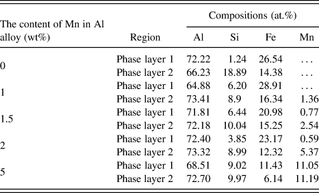
The chemical compositions of each phase layer at different levels of Mn are shown in Table II. By the analysis of Table II, it indicates that phase layer 1 became Al–Fe–Mn–Si quaternary phase from Al–Fe–Si ternary phase, and the chemical composition of phase layer 2 is similar to that of the corresponding polyhedral phase in the Al matrix transition layer. Figure 3 shows a schematic of the intermediate layer and the relationship curve between the Mn content and the thickness of the intermediate layer. The average thickness d is calculated in terms of the following equation:
 $$d = {A {\vphantom {A L}} \right\mathord{\left/\kern-\nulldelimiterspace} L}\quad ,$$
where A and L are the measured area and length of the intermediate layer, respectively.
The chemical compositions of each phase layer.
(a)Schematic illustration of the intermediate layer; (b) a relationship curve between the Mn content and the thickness of the intermediate layer.
In accordance with Fig. 3(b), it indicates that the average thickness of the intermediate layer does not increase apparently with increasing Mn content, and the maximum thickness of the intermediate layer even decreases, as the Mn content is less than 1.5 wt%. However, as the Mn content is more than 2 wt%, the average thickness apparently increases. This shows that addition of Mn can facilitate the growth of the intermediate layer in a certain range.
C. The morphology and type of intermetallic phases in the Al matrix transition layer
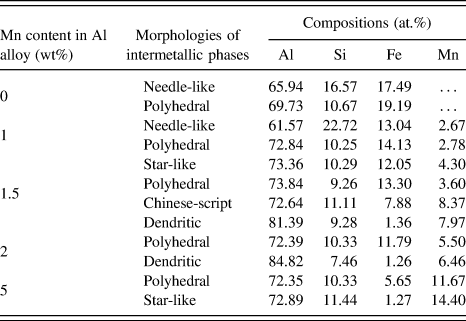
Figure 4 shows cross-sectional SEM micrographs of the specimens obtained with surface treatments by fluxing and hot dipping in the liquid alloy at different levels of Mn at 993 K for 120 s. The chemical compositions of the intermetallic phases in the Al matrix transition layer obtained at different levels of Mn are shown in Table III. According to the SEM and EDS analyses of the morphology and compositions for the intermetallic phases in the Al matrix transition layer, a number of the needle-like and polyhedral phases are formed, as Mn is not added into the dipping bath [Fig. 4(a)]. The needle-like phase is identified as the τ6 phase (Al5FeSi) and more than 40 μm in length. What is more, the polyhedral phase is identified as the τ5 phase (Al8Fe2Si) of which the surface diameter is about 30 μm. When Mn is added into the dipping bath, the needle-like phase starts to decrease and even disappears [in Figs. 4(b)–4(e)]. The needle-like phase is decreased and is less than 30 μm in length; but the polyhedral phase is increased, and its surface diameter is about 20 μm [in Fig. 4(b)]. When the Mn content is increased up to 1.5 wt% [Fig. 4(c)], the needle-like phase disappears, and some complex morphology of iron-rich phases, for example, star-like, Chinese-script, and dendritic phase, of which the maximal surface diameter is about 30 μm, formed and distributed in the Al matrix transition layer regularly. To further increase the Mn content, there just formed some polyhedral phase and a few star-like phase in the Al matrix transition layer, but their surface diameter is even more than 40 μm [Fig. 4(d)]. Meanwhile, a number of dendritic phases are formed in the Al matrix. Some polyhedral and star-like phases become coarse as the Mn content is 5 wt% [Fig. 4(e)], and their surface diameter all is more than 40 μm, even approaching 60 μm.
The chemical compositions of the intermetallic phases in the Al matrix transition layer.
The volume fractions of the total intermetallic phases and the needle-like phases in the Al matrix transition layer are shown in Fig. 5. By analysis of Fig. 5, we can identify that the volume fraction of the needle-like phase in the Al matrix transition layer decreased apparently after adding Mn, but the volume fraction of the total intermetallic phases increased with increasing Mn content.
The volume fractions of the intermetallic phases and the needle-like phase in the Al matrix transition layer. (The intermetallic phases include needle-like, polyhedral, star-like, Chinese-script, and dendritic.)
IV. DISCUSSIONS
A. The influence mechanism of fluxing and hot dipping
The hot dipping treatment has improved the wetting of gray iron specimens by liquid alloy and created a good environment for metallurgical reaction. Above all, the high temperature can facilitate the diffusion of atoms during hot dipping, which makes metallurgical reaction prone to start and Al–7Si/gray iron interface form a metallurgical bonding layer before pouring. The metallurgical bonding layer was identified by the EDS results of the present study [in Fig. 1(d)]. During hot dipping, the surface of gray iron specimens was also coated with a thin Al–7Si alloy layer that maintained a certain temperature until pouring, so the coating would easily fuse with the liquid alloy during pouring. However, the surface of gray iron specimens was easily polluted after removing grease and rust in air. Meanwhile, the thin oxide layer mainly consisting of Al2O3 that formed during immersing the gray iron specimens in the liquid alloy would prevent a direct contact between the liquid alloy and the surface of gray iron specimens. All these make the metallurgical reaction become more and more difficult. To solve these problems, the KF flux was applied in the surface treatment. Not only can the flux protect the gray iron specimens from polluting but also the component of flux can react with the oxide coating, which makes the liquid alloy contact directly and react rapidly with the gray iron specimens. The evolution course of the flux is as follows: at the beginning, the flux covered the surface of the gray iron specimens and formed a uniform salt membrane layer; then, the salt membrane was melted rapidly during hot dipping, making the gray iron specimens' surfaces wet soon by liquid alloy, and metallurgical reaction takes place; finally, the flux was melted into the liquid alloy and this became the slag.
B. Analysis of the effect of Mn on the intermediate layer
From Refs. Reference Balitchev, Jantzen, Hurtado and Neuschutz25 and Reference Akdeniz and Mekhrabov26, we can know that the addition of Si has the restraining effect on the growth of the intermediate layer in solid/liquid diffusion couples. By the analysis of Figs. 2 and 3, we can find that the addition of Mn plays a positive role in facilitating the growth of the intermediate layer in the present experiment. Moreover, for the influencing mechanism of Mn to the intermediate layer, we can analyze the influence of each component on the activity of Al atoms in the Al–Fe–X system. The following equation indicates the role of Si and Mn in the interfacial interactions in the Al–Fe–X system and the growth of the intermediate layer.Reference Akdeniz and Mekhrabov26
 $${\rm{\mu }}_i^{{\rm{excess}}} = RT\ln {{\rm{\gamma }}_i}\quad ,$$
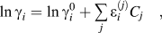 $$\ln {{\rm{\gamma }}_i} = \ln {\rm{\gamma }}_i^0 + \mathop\sum\limits_j {{\rm{\varepsilon }}_i^{(j)}{C_j}} \quad ,$$
where  ${\rm{\mu }}_i^{{\rm{excess}}}$ is the excess chemical potential of solute
 $i$ in the solid solution,
 $R$ is the universal gas constant, and
 $T$ is the absolute temperature, γi is the activity coefficient of the element
 $i$,
 ${\rm{\gamma }}_i^0$ is the activity conversion coefficient independent of component concentration,
 ${\rm{\varepsilon }}_i^{\left( j \right)}$ is the action coefficient of element j to γi, C j is the atom fraction of element j.
The related parameters have been calculated through the Eqs. (6) and (7) to investigate the influence of 1 at.% X on the activity of Al atoms in the Al–Fe–X system at different temperatures as in Ref. Reference Akdeniz and Mekhrabov26. They found that if the value of  ${\rm{\varepsilon }}_{{\rm{Al}}}^{\left( {{\rm{Si}}} \right)}$ was negative, the experimental result indicated that the growth of the intermediate layer was restrained, and if the value of
 ${\rm{\varepsilon }}_{{\rm{Al}}}^{\left( {{\rm{Si}}} \right)}$ was positive, the experimental result indicated that the growth of intermediate layer was facilitated. Hence, the Si enriched in the phase layer 2 could reduce the activity of Al atoms, and prevent the growth of phase layers 1 and 2 from supplying the Al atoms to the phase layer 1. Inversely, Mn could improve the activity of Al atoms. As Mn and Si exist at the same time, the influence of Mn would offset the restraining effect of Si on the activity coefficient of Al. In addition, the concentration of Si in phase layer 1 into what diffused from phase layer 2 was increased after adding Mn, which was shown in Table II. The addition of Mn can contribute to the diffusion of Si from phase layer 2 to layer 1, and the restraining effect of Si on the activity coefficient of Al was also decreased in phase layer 2. For this reason, the additional Mn has naturally facilitated the growth of phase layers 1 and 2 at the Al–Si/gray iron interface. Meanwhile, with increasing Mn content, the effect of Mn on the activity of Al atoms was increased, and the thickness of the intermediate layer was also increased.
In the casting Al–Si alloys, Fe is considered as an impurity element, and the iron-rich phases are hard and brittle phases. If the thickness of the intermediate layer is not appropriate, it would cause the mechanical properties of the joint to become worse. Reference Reference Schubert, Klassen, Zerner, Walz and Sepold27 taught that the appropriate thickness was about 10 μm. A comprehensive analysis of the result is that a sound metallurgical bonding in the Al–7Si alloy/gray iron bimetal composite can be achieved by combining the effect of surface pretreatment and selection of Mn content.
C. The evolution of intermetallic phases in the Al matrix transition layer
In addition, this study has investigated the effect of Mn on the morphology of the interfacial bond zone. Before adding Mn, the Al matrix transition layer consisted of the needle-like τ6 phase and the polyhedral τ5 phase. After adding Mn, it is efficient to restrain the formation and growth of the needle-like phase but facilitate the formation and growth of some different morphology of the α-Al15(FexMn1−x)3Si2 phase. The formation of the α-Al(Fe,Mn)Si phase in the Al matrix transition layer is a complex process. A α-Al15Mn3Si2 ternary phase is mainly formed in the Al–Si–Mn system. During hot dipping, part of Fe atoms diffused into the liquid alloy from the surface of gray iron specimen to replace the lattice place of Mn in the α-Al15Mn3Si2 phase and then translated into the α-Al15(FexMn1−x)3Si2 phase.Reference Mondolfo28 However, Fe atoms are nonuniformly distributed around in the gray iron specimen after hot dipping. This is because that the diffusion reaction can be considered as ideal constant-source diffusion in this case. So Fick's second lawReference Chatterji29 can be applied to calculating the concentration of Fe around the gray iron specimens:
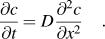 $${{\partial c} \over {\partial t}} = D{{{\partial ^2}c} \over {\partial {x^2}}}\quad .$$
According to the boundary and the initial conditions, the particular solution of Fick's second law is as follows:
 $$c(x,t) = {c_0} + \left( {{c_{\rm{s}}} - {c_0}} \right)\left[ {1 - {\rm{erf}}\left( {{x \over {2\sqrt {{D_{{\rm{Al}}}}t} }}} \right)} \right]\quad .$$
where  $c\left( {x,t} \right)$ is the Fe concentration at distance
 $x$,
 ${c_0}$ is the initial Fe concentration around the gray iron specimens, c s is the Fe concentration in the constant source, D Al is the diffusion coefficient of Fe in liquid Al,
 $x$ is the distance from the diffusion interface,
 $t$ is the diffusion time, and erf is the error function.
To use Eq. (9), the gray iron specimen is exposed to a concentrated Fe solution for a length of time. The Fe concentration is different at different distances from the diffusion interface, but the Mn concentration is uniform. Therefore, the closer to the diffusion interface is, the lower the Mn–Fe ratio is. Meanwhile, the value of x is different, and it leads to form the different morphology of the α-Al15(FexMn1−x)3Si2 phase. As shown in Figs. 4(a)–4(e) and 5, as the Mn content in the Al alloy was less than 1 wt%, the β-Al5(Fe,Mn)Si phase and the α-Al15(FexMn1−x)3Si2 phase could arise as a product of direct precipitation from the liquid alloyReference Tibballs, Horst and Simensen22:
 $${\rm{L1}} \to {\rm{\alpha {\hscale50%-} Al}}\left( {{\rm{Fe,Mn}}} \right){\rm{Si}} + {\rm{L2}}\quad {\rm{,}}$$
 $${\rm{L2}} \to {\rm{\beta {\hscale50%-} Al}}\left( {{\rm{Fe,Mn}}} \right){\rm{Si}} + {\rm{L3}}\quad {\rm{.}}$$
The result is that most Mn atoms were used to facilitate the formation of the polyhedral α-Al15(FexMn1−x)3Si2 phase in the liquid alloy. A small residual amount of Mn atoms dissolved in the needle-like phases that have the growth superiority along a single direction, but the morphology of needle-like phase had not been changed until it is exhausted, forming a needle-like solid solution. Consequently, although Mn have been added in the dipping bath, there still is an appearance of the needle-like β-Al5(Fe,Mn)Si phase in the field near the diffusion interface. But the formation and growth of the needle-like phases have been restrained, so it was less and shorter than that shown in Fig. 4(a). As the Mn content was no less than 1.5 wt%, the primary β-Al5(Fe,Mn)Si phase and the residual liquid alloy started the peritectic reaction and formed the Chinese-script or star-like phase during the solidification process.
 $${\rm{L}} + {\rm{\beta {\hscale50%-} Al}}\left( {{\rm{Fe,Mn}}} \right){\rm{Si}} \to {\rm{\alpha - Al}}\left( {{\rm{Fe,Mn}}} \right){\rm{Si}}\quad {\rm{.}}$$
With increasing Mn content, the peritectic reaction was more sufficient. As the Mn content was in the range of 1.5–2 wt%, the needle-like phase disappeared gradually in the Al matrix transition layer. This indicates that it has reached an ideal state to restrain the forming of the needle-like phase. As the Mn content was more than 5 wt%, the intermetallic phases that formed in the Al matrix transition layer was less than before quantitatively but became coarse and irregular. It is because that the high Mn content causes local segregation, which makes the polyhedral phase grow abnormally. These phases can affect the mechanical properties of the Al–Si alloy matrix. Meanwhile, the volume fraction of the intermetallic phases in the Al matrix transition layer increases obviously with increasing Mn content (Fig. 5). This shows that the addition of Mn has facilitated the formation and growth of the intermetallic phases in the Al matrix transition layer. But the Mn content must be controlled in a certain range.
V. CONCLUSIONS
The present study tracked the evolution of the interfacial bond zone which forms during the course of a gravity die casting process. The surface treatment consisted of fluxing using the KF flux solution and hot dipping in an Al–7Si alloy with different levels of Mn at 993 K for 120 or 300 s. From the obtained results, the following conclusions can be drawn:
(1) An integrated continuous metallurgical bonding layer at the interfacial bond zone have been achieved by combining the effect of the fluxing and hot-dipping surface treatment, which effectively improved the quality of castings and the finished product ratio. Besides, it turned out that the flux solution (containing 46% KF and 54% KCl) is fit for Al–7Si/gray iron composite casting.
(2) The addition of Mn in dipping bath could effectively inhibit the formation of the needle-like phases in the Al matrix transition layer. Inversely, it facilitated the formation and growth of α-Al15(FexMn1−x)3Si2 phases and also the growth of the continuous metallurgical bonding layer. Furthermore, when the Mn content was 1.5 wt%, a significant improvement has been made in the metallurgical bonding at the Al–7Si/gray iron interface.
ACKNOWLEDGMENT
This work was carried out with the financial support from the National Natural Science Foundation of China (Grant No. 50831003).