I. INTRODUCTION
Graphene, a single layer of carbon atoms, has potential use in next generation nanodevices because of its unique electrical, optical, catalytic, and mechanical properties.Reference Novoselov, Geim, Morozov, Jiang, Katsnelson, Grigorieva, Dubonos and Firsov1 However, due to the special two-dimensional structure, high surface energy, and intrinsic van der Waals forces of pure graphene, it tends to aggregate and entangle spontaneously, thereby limiting its technological applications. To solve this problem, various modified graphenes have been prepared.Reference Bai, Xu, Zhao, Li and Shi2, Reference Xu, Bai, Lu, Li and Shi3 Among them, graphene oxide (GO) is the most easily synthesized and dispersed, and is thus widely used in materials chemistry as well as basic research.Reference Wang, Zhi and Müllen4, Reference Liu, Liu, Huang, Ma, Yin, Zhang, Sun and Chen5 Similar to graphene, GO is obtained by the exfoliation of graphite oxide and has a layered structure with oxygen functional groups on the basal planes and edges.Reference Kotov, Dékány and Fendler6 Thus, GO is suitable for developing graphene composites with other materials. Considerable progress has been made in the preparation of GO–polymer composites, and significant enhancements in the mechanical and thermal properties of GO have been observed.Reference Cote, Cruz-Silva and Huang7, Reference Salavagione, Gómez and Martínez8
Conducting polymers are some of the most attractive electrode materials because of their high conductivity and redox activity.Reference Nyström, Razaq, Strømme, Nyholm and Mihranyan9 Among various electroactive polymers, polyaniline (PANI) is particular interesting because of its unique properties, such as good environmental stability, interconvertible intrinsic redox states, and high electrochemical activity.Reference Li, Huang and Kaner10 However, rapid polymer degradation due to swelling and shrinkage can lead to poor cycle stability. One way to overcome this drawback is to support the conducting polymer on a carbon-based material.Reference Wang, Li and Xia11 Indeed, various carbon materials have been used in preparing composite materials.Reference Wang, Li and Xia11, Reference Hughes, Shaffer, Renouf, Singh, Chen, Fray and Windle12 GO has been demonstrated to be a good filler for polymer nanocomposites.Reference Cassagneau, Guérin and Fendler13 When the advantages of carbon materials are combined with those of PANI, the resulting composites acquire synergistic features.Reference Wang, Li and Xia11, Reference Gupta and Miura14
Well-known processes for the preparation of noncovalent conjugate PANI–GO composites include mixing of preformed PANI with GOReference Yang, Zhai, Wan, Wang and Jiang15 and in situ chemical polymerization of aniline monomer in solution in the presence of GO.Reference Wang, Hao, Yang, Lu and Wang16 However, using noncovalent bonding as the immobilization method has the disadvantage of PANI being easily desorbed from the surface of GO during use because no strong interfacial bonding exists between GO and PANI. Graphene is also substantially hindered in the stiffening or strengthening of the composite through traditional shear lag-based mechanisms, which result in nanostructured holes or matrix flaws. These phenomena significantly affect the manufacture of high-performance graphene-reinforced composites. Conversely, the covalent attachment of PANI onto GO ensures the sufficiency of immobilization of PANI without leaching from the substrate surface during use.Reference Henry, Tutt, Galloway, Davidson, McWhorter, Soper and McCarley17
In this study, we report an easy approach for immobilizing PANI onto GO sheets. PANI nanofibres are functionalized with cysteamine, which contains the amine functional group (–NH2). The amine group has high reactivity that enables it to react easily with many other chemicals. On the other hand, the large amount of oxygenous groups on the GO sheets enables easy interaction with the amine groups of PANI–NH2 through covalent bonds. The PANI–GO conjugate is inexpensive and easily scalable. The nanocomposite is easily synthesized at room temperature in an aqueous medium, and can be dispersed in solvents such as toluene to form colloidal dispersions (just after 2 h of sonication). PANI–NH2covalently attached onto GO may open new perspectives on reinforcing nanocomposites.
II. EXPERIMENTAL
A. Materials
Natural flake graphite (325 mesh) was purchased from Alfa Aesar (Haverhill, MA). Cysteamine was obtained from Tokyo Chemical Industry Co., Ltd. (Tokyo, Japan). 1-(3-Dimethylaminopropyl)-3-ethylcarbodiimide (EDC) was bought from Suzhou Highfine Biotech. Co., Ltd. (Suzhou, China). A pH 4.0 citric/phosphate aqueous buffer solutionReference Zhang, Zujovic, Peng, Bowmaker, Kilmartin and Travas-Sejdic18 was prepared by mixing 61.45 mL of 0.1 M citric acid and 38.55 mL of 0.2 M dibasic sodium phosphate (Na2HPO4). Other reagents were analytical grade and obtained from Xi’an Chemical Reagent Factory (Xi'an, China). The aniline monomer was purified by vacuum distillation before use and stored in a sealed container at 4 °C. All other reagents were used as received.
B. Synthesis of functionalized PANI nanofibers
PANI nanofibers were synthesized under ambient conditions by interfacial polymerization.Reference Lahiff, Woods, Blau, Wallace and Diamond19 The aniline monomer was dissolved in toluene and the oxidant (ammonium persulfate) was dissolved in 1 M hydrochloric acid. PANI nanofibers initially appeared at the interface and then migrated into the aqueous phase. When the reaction was complete, the product was purified by centrifugation and suspended as a colloid in water. PANI nanofibers were subsequently modified with cysteamine (0.1 and 1 mmol) by refluxing at 100 °C for 2 h in an aqueous pH 4 buffer.Reference Crean (neé Lynam), Lahiff, Gilmartin, Diamond and O’Kennedy20 All experiments were carried out under identical conditions using 30 mL of ∼1.5 mg/mL PANI aqueous dispersion. The product was purified by centrifugation and resuspended as a colloid in distilled water. The products of the 0.1 and 1 mmol cysteamine reactions are denoted as PANI–NH2A and PANI–NH2B, respectively.
C. Preparation of GO dispersion
Graphite oxide was prepared from natural flake graphite by the modified Hummers method.Reference Hummers and Offeman21 Graphite (2 g) and sodium nitrate (NaNO3) (1 g) were mixed with concentrated sulfuric acid (H2SO4) (46 mL) in a 250 mL flask at 0 °C, and the mixture was stirred for 15 min in an ice bath. Subsequently, 6 g of potassium permanganate (KMnO4) was added in small portions to prevent temperature increase beyond 20 °C, and the mixture was stirred for another 2 h. The temperature of the reaction mixture was then increased to 35 °C and the mixture was stirred for 30 min. About 92 mL of water was gradually added to the reaction mixture. The suspension was diluted with 280 mL of warm water and treated with 30% hydrogen peroxide (H2O2). The resulting suspension was separated from the reaction mixture by filtration. The yellow-brown graphite oxide powders were washed with water and dried under vacuum at 40 °C for 24 h. After sonicating the prepared graphite oxide in distilled water (1 mg/mL) for 2 h, the GO dispersion was obtained.
D. Covalent attachment of PANI onto GO
About 20 mL of 1 mg/mL GO dispersion was mixed with the same volume of 1 mg/mL PANI–NH2B nanofiber dispersion with stirred at room temperature. PANI was covalently conjugated with GO by adding 40 mg of EDC to the dispersion, and the mixture was stirred overnight. The PANI–GO hybrid was centrifuged, washed with distilled water several times, and dried in a vacuum oven at 40 °C for 24 h to obtain the products.
E. Characterization
Fourier transform infrared (FTIR) spectra of the samples were obtained on a Bruker Tensor 27 Spectrometer (Karlsruhe, Germany). Samples were dried under vacuum for 4 h prior to the process of obtaining FTIR spectra and then mixed with dried potassium bromide (KBr). Thermogravimetric analysis (TGA) was carried out using a thermogravimetric analyzer (SDT Q600) at a heating rate of 10 °C/min in nitrogen. Field emission scanning electron microscopy (FESEM; S-4800) and transmission electron microscopy (TEM; H-600) were used to investigate the morphology of the samples.
III. RESULTS AND DISCUSSION
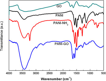
The scheme for synthesis of the hybrid is shown in Fig. 1. During the attachment of cysteamine to PANI, the thiol nucleophile attaches onto the electrophilic quinoid rings in the PANI backbone.Reference Acevedo, Salavagione, Miras and Barbero22Figure 2 shows the FTIR spectra of GO, PANI, PANI–NH2, and PANI–GO. For PANI, the 1570 cm−1 band is characteristic of quinone diimine ring-stretching deformation, whereas the 1497 cm−1 band indicates benzenoid diamine ring stretching. Quinone diimine rings are observed in the PANI backbone. These rings enable the grafting of cysteamine with PANI. Modified PANI–NH2 nanofibers were purified by centrifugation to remove by-products and any remaining unreacted species. By the third centrifugation, the supernatant becomes clear, which indicates the removal of all initial reactants. In the PANI–NH2 spectra, the presence of a band at 1290 cm−1 (CH2–S) as well as weak doublets at 736 and 730 cm−1 (C–S) suggest successful functionalization.Reference Lahiff, Woods, Blau, Wallace and Diamond19 The peaks at 3446, 1700, and 1386–1082 cm−1for GO are attributed to the OH, C = O in COOH and C–O in the COH/COC (epoxy) functional groups, respectively. All these characterizations are identical to the standard GO spectrum. Carboxylic groups that can react with the amine group are also observed on the GO surface.
Scheme for synthesis of the hybrid.

FTIR spectra of GO, PANI, PANI–NH2, and PANI–GO.

The covalent attachment of PANI–NH2 onto GO was verified by FTIR spectroscopy. The spectrum of PANI–GO retains most of the bands of PANI, but is distinctly different from the spectra of PANI–NH2 and GO. The doublet (N–H stretching of primary amine) disappears and a sharp N–H stretching band appears at 3427 cm−1, which confirms the amidation of the amino group of PANI–NH2 with the carboxyl group of GO. The peak at about 1638 cm−1 is found to be associated with C = O stretching vibration. Some transmission bands are slightly shifted, which indicates a change in the local chemical environment, consistent with covalently linked GO molecules. Compared with the peaks of GO, the C = O peak of PANI–GO is downshifted to 1638 cm−1, which indicates a change in the C = O environment, consistent with the formation of the CONH bond. This shift is not observed when PANI and GO are mixedReference Yang, Zhai, Wan, Wang and Jiang15 rather than reacted, which confirms that this shift is evidence of covalent bonding. All these characteristic peaks validate the covalent attachment.
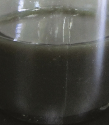
GO cannot be dispersed in most organic solvents, whereas PANI–GO shows better dispersion in organic solvents such as toluene to form colloidal dispersions (Fig. 3). Thus, covalent bonding has occurred and significantly affected the dispersibility of the samples in different solvents. Given this good dispersion in organic solvents, composite has potential applications in flexible electronic devices through traditional solution processing techniques.
Photograph of PANI–GO dispersion.

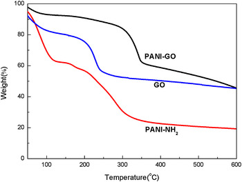
TGA result is a complementary technique that can reveal the thermal stability. Figure 4 reveals that PANI–NH2, GO, and PANI–GO have very different decomposition profiles. The onset of PANI–NH2 and GO bulk decomposition occur at 170 and 200 °C, respectively; the onset for PANI–GO occurs at 320 °C. The decomposition temperatures of PANI–GO are higher than those of PANI–NH2 and GO, which is consistent with covalent bond reactivity. Compared with PANI–NH2and GO, the thermal stability of PANI–GO is increased because amidation linkage formation occurs with the loss of surface functionalization.
TGA curves of PANI–NH2, GO, and PANI–GO.

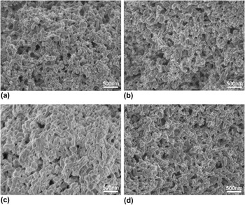
The FESEM images show that the nanofibers synthesized by interfacial polymerization have a uniform diameter distribution [Fig. 5(a)]. After refluxing with cysteamine, the fiber morphology remains unaffected. The surface roughness of the nanofibers increases after reflux with cysteamine, which confirms the occurrence of functionalization.Reference Lahiff, Woods, Blau, Wallace and Diamond19 Compared with PANI–NH2A [Fig. 5(b)] and PANI–NH2B [Fig. 5(c)], the surface roughness of the nanofibers increase with increased ratio of cysteamine to PANI. Therefore, the degree of side-chain attachment can be controlled simply by altering the amount of nucleophile added during reflux.Reference Crean (neé Lynam), Lahiff, Gilmartin, Diamond and O’Kennedy20 The nanofibers become uniform and smooth when PANI–NH2B reacts with GO [Fig. 5(d)]. The surface morphology of the nanofibers appears to be altered, which suggests successful attachment.
SEM images of (a) PANI, (b) PANI–NH2A, (c) PANI–NH2B, and (d) PANI–GO.

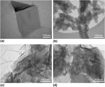
TEM was used to study the morphology of the samples further. Figure 6(a) shows the lamellar structure of GO nanosheets. Figure 6(b) shows the morphology of PANI–NH2 nanofibers. Figures 6(c) and 6(d) show the distinct difference in the morphology of the PANI–GO composites from that of the starting GO and PANI–NH2. The PANI nanofibers are enwrapped by GO, which further confirms the successful tethering of PANI onto GO. The PANI nanofibers can be observed in almost all regions, indicating uniform dispersion of the nanofibers in the GO matrix. Compared with the images of GO [Fig. 6(a)] and PANI–GO [Figs. 6(c) and 6(d)], the layered structures of GO become clearer in PANI–GO. Thus, covalent bond can weaken the interactions among GO sheets and restrict the aggregation of GO sheets.
TEM images of (a) GO, (b) PANI–NH2, and (c, d) PANI–GO.

IV. CONCLUSION
A covalently bonded PANI–GO hybrid was readily synthesized via the chemical reaction of functionalized PANI with GO in an aqueous solution. The covalent bonding of PANI–GO was confirmed by FTIR spectroscopy. The morphology of GO sheets is significantly influenced by the addition of PANI nanofibers. Covalent bonding is responsible for the superior material characteristics, such as excellent solvent dispersibility and high environmental (chemical and thermal) degradation stability, which may also benefit the lifetime of related devices. These results may enable further development of novel electroactive materials based on graphene and intrinsically conducting polymers, as well as the fabrication of corresponding flexible electronic devices through traditional solution processing techniques.
ACKNOWLEDGMENTS
The author gratefully acknowledges the support of Prof. Xinli Jing and the research group of functional polymers in Xi’an Jiaotong University.