1. INTRODUCTION
Global Navigation Satellite System (GNSS)-based full attitude determination needs multiple non-collinear antennae (at least three) firmly mounted on a platform's body, and Integer Ambiguity Resolution (IAR) is key.
Existing IAR techniques can be mainly divided into two categories (Kim and Langley, Reference Kim and Langley2000). The first category is a search technique in the ambiguity domain, such as Least squares Ambiguity Search Technique (LSAST), Ambiguity search using Constraint Equation (ARCE) and the Least-squares Ambiguity Decorrelation Adjustment (LAMBDA) method. LSAST (Hatch, Reference Hatch1990) and ARCE (Park et al., Reference Park, Kim, Lee and Jee1996) divide integer ambiguities into independent and dependent parts and perform a search using only the independent part. These methods have high computational efficiency, but there is no theoretical guideline to set the size of the search space which is critical to performance (Park and Teunissen, Reference Park and Teunissen2009). The most popular methods of the first category are based on the LAMBDA method proposed by Teunissen (Reference Teunissen1995). For attitude determination, there is usually some a priori information, such as baseline configuration and attitude angle provided by other sensors. By utilising the a priori information, the reliability and success rate of GNSS attitude determination can be improved. However, the a priori information is nonlinear, and the standard LAMBDA method can only be used for unconstrained or linearly constrained GNSS models. To utilise the baseline length constraint, Teunissen (Reference Teunissen2010) integrated the nonlinear constraints of baseline length into an objective function and proposed a nonlinear constrained integer least square method (C-LAMBDA). By making use of the Monte Carlo sampling method, Sun et al. (Reference Sun, Han and Chen2017) directly used the quaternion probability distribution to derive the probability density function of ambiguities, and then utilised the LAMBDA method to fix the ambiguities. This method can realise ultra-short baseline constrained multi-antennae attitude determination and the idea is novel, but the complex process of Monte Carlo sampling affects its real-time performance. Giorgi et al. (Reference Giorgi, Teunissen, Verhagen and Buist2009) extended the LAMBDA method for multi-antennae attitude determination and proposed the Multivariate Constrained LAMBDA method (MC-LAMBDA), which is based on a complex and rigorous non-ellipsoidal search strategy. The MC-LAMBDA method has high efficiency and a high success-rate, and its performance has been demonstrated (Teunissen et al., Reference Teunissen, Giorgi and Buist2011; Giorgi, Reference Giorgi2010; Giorgi et al., Reference Giorgi, Teunissen, Verhagen and Buist2012).
With the development of this technique, highly accurate a priori information of pitch and roll can be obtained by Micro-Electromechanical Systems-Inertial Measurement Unit (MEMS-IMU)/GNSS integrated navigation systems (Alban, Reference Alban2004; Buist, Reference Buist2013; Eling et al., Reference Eling, Zeimetz and Kuhlmann2013). Rigorously integrating this tight angular a priori information into the objective function would strengthen the GNSS attitude model and benefit the reliability and availability of GNSS single-epoch full attitude determination, but it generates a new problem: the inefficiency of search in the ambiguity domain. This tight angle-related term in the objective function makes the ambiguity-related term become a very small amount, even for the correct ambiguities (see Figure 3). Under these conditions, a non-ellipsoidal search strategy cannot help us to accelerate the search, and the first category may be unsuitable for real-time application.
The second IAR search technique category is a technique in the coordinate domain, and it can directly use angular a priori information to compress the search space and accelerate the search. The well-known method based on this category is the Ambiguity Function Method (AFM) (Counselman and Gourevitch, Reference Counselman and Gourevitch1981) The poor efficiency of AFM hinders its real-time application and to improve this, Knight (Reference Knight1994) proposed a new method for instantaneous ambiguity resolution, which realised AFM in the attitude domain rather than the coordinate domain and achieved high reliability and efficiency with a priori information of attitude. Cellmer et al. (Reference Cellmer, Wielgosz and Rzepecka2010) and Cellmer (Reference Cellmer2012; Reference Cellmer2013) proposed the Modified Ambiguity Function Approach (MAFA) which was based on a cascade adjustment with successive linear combinations of L1 and L2 carrier phase observations and a simple search procedure. The efficient use of multi-frequencies ensured MAFA had a good real-time performance. To ensure the necessary condition to obtain a correct solution of MAFA, Nowel et al. (Reference Nowel, Cellmer and Kwaoniak2018) proposed a new method to apply a search procedure in MAFA, which calculated the search step and region based on the size of Voronoi cell, calculating empirically rather than analytically. Cellmer et al. (Reference Cellmer, Nowel and Kwaśniak2018) determined the search region based on the confidence level and further analysed the search step of MAFA through simulation, and the search step is suggested to be 0.5λ in this paper. Given a constant ultra-short baseline length constraint, Chen and Sun (Reference Chen and Sun2016) used the nominal accuracy of attitude and a regulator to calculate the search step, and then search the optimal ambiguity vector corresponding to coordinate points by making use of only phase observations. This method improved the efficiency of AFM and realised single frequency and single epoch attitude determination in urban environments. However, these methods mentioned above improve AFM in many ways, but they do not have the analytical search step and do not establish a search model for multi-antennae attitude determination.
In this contribution, we emphasise the efficient use of nonlinear a priori information of pitch and roll in a multi-antennae attitude model and propose a reliable multivariate constrained attitude determination method based on attitude domain search. The analytical attitude search step is derived by utilising a priori information of pitch and roll, and all the integer candidates are determined by traversal search in the three-dimensional attitude domain. This makes our method theoretically more efficient and more rigorous. A non-iterative approximate method is proposed to simplify the iterative computation in calculating an objective function value which is due to nonlinear a priori information. This simplification further decreases the computation load.
This paper is organised as follows. First, a GNSS multi-antennae attitude model is introduced. Second, the a priori information of pitch and roll is rigorously integrated into the objective function of the GNSS multi-antennae attitude model, and how the tight a priori information affects the efficiency of the search technique in the ambiguity domain is analysed. Third, a model of attitude domain search and an analytical method to calculate the search step are proposed. In addition, a modified strategy to simplify the iterative computation in calculating the objective function value is given. Finally, we report on static and dynamic tests, and both tests indicate the high efficiency, high reliability and high success rates of our proposed method.
2. THE MULTI-ANTENNAE GNSS ATTITUDE MODEL
We consider a set of n + 1 antennae (n independent baselines) simultaneously tracking the same t + 1 satellites on a single frequency. The model of multi-antennae attitude determination was given by Teunissen (Reference Teunissen2008) as:
 $$[{\bi P}_{1}\quad {\bi P}_{2} \cdots {\bi P}_{n}] = {\bi GRA} \quad {\bi P}_{1}\quad {\bi P}_{2} \cdots {\bi P}_{n} \in {\open R}^{t \times 1}\comma \; {\bi G} \in {\open R}^{t \times 3}\comma \; {\bf A} \in {\open R}^{3 \times n}\comma \; {\bi R} \in {\open O}^{3 \times 3} $$
 $$\eqalign{[{\brPhi}_1\quad {\brPhi}_{2} \cdots {\brPhi}_{n}] & = \displaystyle{{1}\over{\lambda}} {\bi GRA} + [{\bi N}_{1}\quad {\bi N}_{2} \cdots {\bi N}_{n}] \quad {\brPhi}_1\quad {\brPhi}_{2} \cdots {\brPhi}_{n} \in {\open R}^{t \times 1}\comma \; \cr & \quad {\bi N}_1 \quad {\bi N}_2 \cdots {\bi N}_{n} \in {\open Z}^{t \times 1}} $$
where Φ1, Φ2 · · · Φn, P1, P2 · · · Pn are the phase and code Double Difference (DD) observations derived at each baseline, G is the matrix of DD line-of-sight vectors, N1, N2 · · · Nn are vectors of integer ambiguities for each baseline, λ is the wavelength, A is the matrix of baseline coordinates in the body frame, R is the orthogonal matrix which describes the relative orientation between the body and East-North-Up (ENU) frames, 𝕆3×3 denotes the set of 3 × 3 matrices of which the column vectors form an orthonormal span, ℝa×b denotes the set of a × b matrices of which the entries are real-valued and ℤt×1 denotes the set of t × 1 matrices of which the entries are integers.
R can be parameterised with attitude angles as:
 $${\bi R} = \left[\matrix{ \sin \theta \cos \beta & \sin \theta \sin \beta \sin \gamma + \cos \theta \cos \gamma & \sin \theta \sin \beta \cos \gamma - \cos \theta \sin \gamma \cr \cos \theta \cos \beta &\cos \theta \sin \beta \sin \gamma - \sin \theta \cos \gamma &\cos \theta \sin \beta \cos \gamma + \sin \theta \sin \gamma \cr \sin \beta &- \cos \beta \sin \gamma &- \cos \beta \cos \gamma}\right]$$
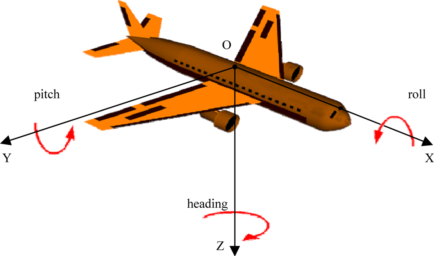
where θ, β, γ stand for heading, pitch and roll (see Figure 1).
Definition of the body frame and attitude angle.

R can be rewritten as:
 $${\bi R} = \left[\matrix{ r_{11} & r_{12} & r_{13} \cr r_{21} & r_{22} & r_{23} \cr r_{31} & r_{32} & r_{33} }\right]$$
In theory, if all the entries of first and second column of R are known, the heading, pitch and roll can be calculated according to the following equations:
 $$\theta = \hbox{arctan}\left(\displaystyle{{r_{11}}\over{r_{21}}}\right)\quad \beta = \hbox{arcsin}\lpar r_{31}\rpar \quad \gamma = -\hbox{arcsin}\left(\displaystyle{{r_{32}}\over{\cos \beta}}\right)$$
To measure full attitude, one needs at least two non-collinear baselines (three antennae). If there are only three antennae available, the dimensions of A and R are transferred into 2 × 2 and 3 × 2.
Equations (1) and (2) can be written as:
 $${\bi P} = {\bi BM} $$
 $${\brPhi} = \displaystyle{{1}\over{\lambda}} {\bi BM} + {\bi N} $$
where Φ = vec([Φ1 Φ2 · · · Φn]), P = vec([P1 P2 · · · Pn]), N = vec([N1 N2 · · · Nn]), B = AT ⊗ G, M = vec(R), ⊗ is Kronecker product and vec is the operator which stacks the columns of a matrix below each other.
3. AMBIGUITY DOMAIN SEARCH WITH TIGHT ANGULAR A PRIORI INFORMATION
Without regard for angular a priori information, Giorgi et al. (Reference Giorgi, Teunissen, Verhagen and Buist2009) used the least-squares principle to derive the objective function of multi-antennae attitude determination as:
 $${\bi C}_{1}\lpar {\bi N}\rpar = \Vert {\bi N} - \hat{{\bi N}}\Vert _{{\bi Q}_{\hat{N}\hat{N}}}^{2} + \Vert {\bi vec}\lpar {\hat{\bi R}}\lpar {\bi N}\rpar - {\mathop{\bi R} \limits^{\smile}}\lpar {\bi N}\rpar \rpar \Vert _{Q_{\hat{R}\lpar N\rpar \hat{R}\lpar N\rpar }}^{2} $$
with:
 $${\mathop{\bi R} \limits^{\smile}}\lpar {\bi N}\rpar = \hbox{arg} \mathop{\min}\limits_{R \in {\open O}^{3 \times 3}} \Vert {{\bi vec}}\lpar {\hat{\bi R}}\lpar {\bi N}\rpar - {\bi R}\rpar \Vert _{{\bi Q}_{\hat{R}\lpar N\rpar \hat{R}\lpar N\rpar }}^{2} $$
where  $\hat{{\bi N}}$ is the float solution of the integer ambiguity vector,
 ${\hat{\bi R}}\lpar N\rpar $ is the linear least-square solution conditioned on the knowledge of N and
 ${\bi Q}_{\hat{N}\hat{N}}$,
 ${\bi Q}_{\hat{R}\lpar N\rpar \hat{R}\lpar N\rpar }$ are the variance-covariance (v-c) matrices of
 $\hat{{\bi N}}$ and
 ${\hat{\bi R}}\lpar {\bi N}\rpar $ respectively. The first term in Equation (8) can be seen as an ambiguity-related term, and the second term can be seen as an orthogonal matrix-related term.
We assume the a priori information of pitch and roll are uncorrelated, and the noise is a white Gaussian distribution with zero mean. Taking the a priori information as an observation (Gong et al., Reference Gong, Zhao, Pang, Duan and Wang2015), the objective function with a priori information of pitch and roll can be given as:
 $${\bi C}_{2}\lpar {\bi N}\rpar = \Vert {\bi N} - \hat{{\bi N}}\Vert _{{\bi Q}_{\hat{N}\hat{N}}}^{2} + \Vert {\bi vec}\lpar {\hat{\bi R}}\lpar {\bi N}\rpar - {\mathop{\bi R} \limits^{\smile}}\lpar {\bi N}\rpar \rpar \Vert _{{\bi Q}_{\hat{R}\lpar N\rpar \hat{R}\lpar N\rpar }}^{2} + \displaystyle{{\Vert {\mathop{\beta} \limits^{\smile}} - \hat{\beta}\Vert }\over{\sigma_{\beta}^{2}}} + \displaystyle{{\Vert {\mathop{\gamma} \limits^{\smile}} - \hat{\gamma}\Vert ^{2}}\over{\sigma_{\gamma}^{2}}} $$
with:
 $${\mathop{\bi R} \limits^{\smile}}\lpar {\bi N}\rpar = \hbox{arg} \mathop{\min}\limits_{R \in {\open O}^{3 \times 3}} \left(\Vert {\bi vec}\lpar {\hat{\bi R}}\lpar N\rpar - {\bi R}\rpar \Vert_{{\bi Q}_{\hat{R}\lpar N\rpar \hat{R}\lpar N\rpar }}^{2} + \displaystyle{{\Vert {\mathop{\beta} \limits^{\smile}} - \hat{\beta}\Vert^{2}}\over{\sigma_{\beta}^{2}}} + \displaystyle{{\Vert {\mathop{\gamma} \limits^{\smile}} - \hat{\gamma}\Vert^{2}}\over{\sigma_{\gamma}^{2}}}\right)$$
where  $\hat{\beta}$,
 $\hat{\gamma}$ stand for a priori measurements of pitch and roll,
 $\sigma_{\beta}^{2}$,
 $\sigma_{r}^{2}$ are the variance of
 $\hat{\beta}$,
 $\hat{\gamma}$ and
 ${\mathop{\beta} \limits^{\smile}}$,
 ${\mathop{\gamma} \limits^{\smile}}$ are pitch and roll derived by
 ${\mathop{\bi R} \limits^{\smile}}\lpar {\bi N}\rpar $. Let the third term and fourth term be called angle-related terms.
Although Equation (8) uses nonlinear baseline configuration constraints rigorously, it causes a potential drawback for a search technique in the ambiguity domain - an increased numerical complexity (Teunissen, Reference Teunissen2012). It is well-known that Giorgi (Reference Giorgi2010) overcame this drawback through a non-ellipsoidal search strategy which is based on the use of an easy-to-evaluate bounding function. Its key point is to set a small enough χ 2 through the bounding function, and then enumerate all the candidates in the Ω(χ 2) Equation (12) to minimise C1(N):
 $$\Omega \lpar \chi^{2}\rpar = \lcub {\bi N} \in {\open Z}^{nt \times 1}\vert {\bi C}\lpar {\bi N}\rpar \leq \chi^{2}\rcub $$
with:
 $${\bi C}\lpar {\bi N}\rpar = \Vert {\bi N} - \hat{{\bi N}}\Vert _{{\bi Q}_{\hat{N}\hat{N}}}^{2} $$
The real search space without angular a priori information can be expressed as:
 $$\Omega_{1}\lpar \chi^{2}\rpar = \lcub {\bi N} \in {\open Z}^{nt \times 1}\vert {\bi C}_{1}\lpar {\bi N}\rpar \leq \chi^{2}\rcub $$
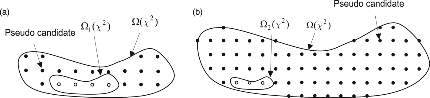
The final search procedure for a non-ellipsoidal search strategy is implemented in Ω(χ 2), and Ω(χ 2) does not consider the orthogonal matrix-related term in the objective function C 1(N), so it enlarges the search space (see Figure 2(a)). Fortunately, without a priori angle information, for the correct ambiguities, the ambiguity-related term in C 1(N) is a large weight (see Figure 2), and discarding the orthogonal matrix-related term would not enlarge the search space obviously, and the efficiency of non-ellipsoidal search strategy should be excellent. But influenced by the accurate angular a priori information, this situation would be changed.The real search space with angular a priori information can be expressed as:
Illustration of search spaces and the pseudo candidate: Ω (χ 2) is the search space considering only ambiguity-related factors, Ω1 (χ 2) is the real search space without considering a priori angular information, Ω2 (χ 2) is the real search space fully considering a priori angular information and the black points are the pseudo candidates.

 $$\Omega_{2}\lpar \chi^{2}\rpar = \lcub {\bi N} \in {\open Z}^{nt \times 1}\vert {\bi C}_{2} \lpar {\bi N}\rpar \leq \chi^{2}\rcub $$
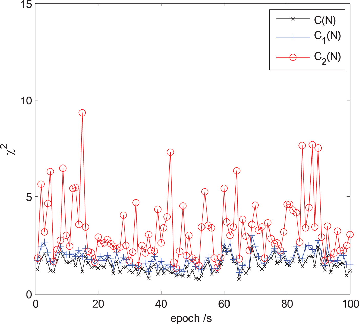
Due to the angle-related term in Equation (10), the first ambiguity-related term of Equation (10) for correct ambiguities is usually a small weight (see Figure 3).
Demonstration of the small weight of the first ambiguity-related term in Equation (10) for correct ambiguities. The value of C(N) is much smaller than C2(N) and nearly equal to C1(N).

Figure 2 shows the value of C(N), C1(N), C2(N) calculated from the correct ambiguities for the first 100 epochs' data of the static test described in Section 4. C(N) is the value of the ambiguity-related term, and C1(N) and C2(N) are respectively the objective function values without and with angular a priori information.
As shown in Figure 3, even if one sets χ 2 with the correct ambiguities, the size of Ω(χ 2) is still very large, and there will be many pseudo candidates which are in Ω(χ 2), but not in Ω2(χ 2) (see Figure 2(b)). This means that the nonlinear least-square problem Equation (11) has to be evaluated many times, and would be very time-consuming.
As analysed above, the rigorous inclusion of a priori information of attitude angle will decrease the efficiency of the search in the ambiguity domain. First, the ambiguity-related term C(N) becomes a small weight in the objective function C2(N), and it makes it impossible to find a small enough χ 2 to ensure there are not too many pseudo candidates in Ω(χ 2). Second, the evaluation of nonlinear least-square problem Equation (11) involves iteration, and it further increases the computation load.
In contrast to the search technique in the ambiguity domain, the search technique in the coordinate domain search can use a priori information of attitude to compress the search space directly and overcomes the problem.
4. AMBIGUITY SEARCHING ALGORITHM IN THE ATTITUDE DOMAIN
4.1. Search model in attitude domain
From Equation (3), the vector M can be parametrised with the attitude angle as:
 $${\bi M} = {\bi M}\lpar \theta\comma \; \beta\comma \; \gamma\rpar $$
For the DD carrier phase equation, the integer ambiguities can be denoted as the following simplified equation:
 $${\bi N} = {\brPhi} - \displaystyle{{1}\over{\lambda}} {\bi BM}\lpar \theta\comma \; \beta\comma \; \gamma\rpar $$
Typically, the error of carrier phase measurement is less than 0·25 cycles, and thus Equation (17) can be expressed as
 $${\bi N} = {\bi round} \left({\brPhi} - \displaystyle{{1}\over{\lambda}} {\bi BM}\lpar \theta\comma \; \beta\comma \; \gamma\rpar \right)$$
where round is a function of rounding to the nearest integer value.
Equation (18) indicates that the integer ambiguities can be seen as the function of attitude. Taking no account of the computation load, one can enumerate every possible attitude angle to determine ambiguity candidates through Equation (18).
4.2. An analytic method to calculate search step
In the classic AFM approach, to satisfy the necessary condition that the final solution is exactly at the point of candidates, the search step is suggested to be less than 0 · 1λ (Han and Rizos, Reference Han and Rizos1996). In our method, the ambiguity candidates are determined by searching in the attitude domain and there is no need to satisfy the condition above.
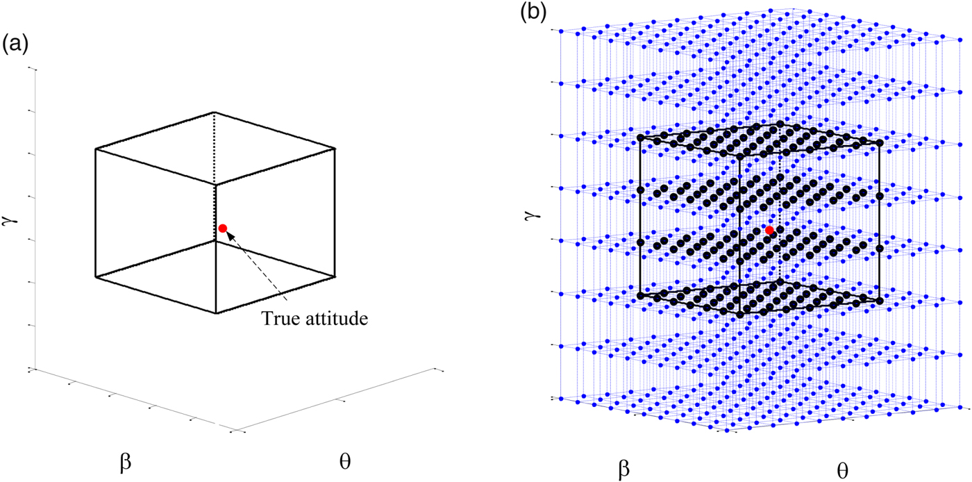
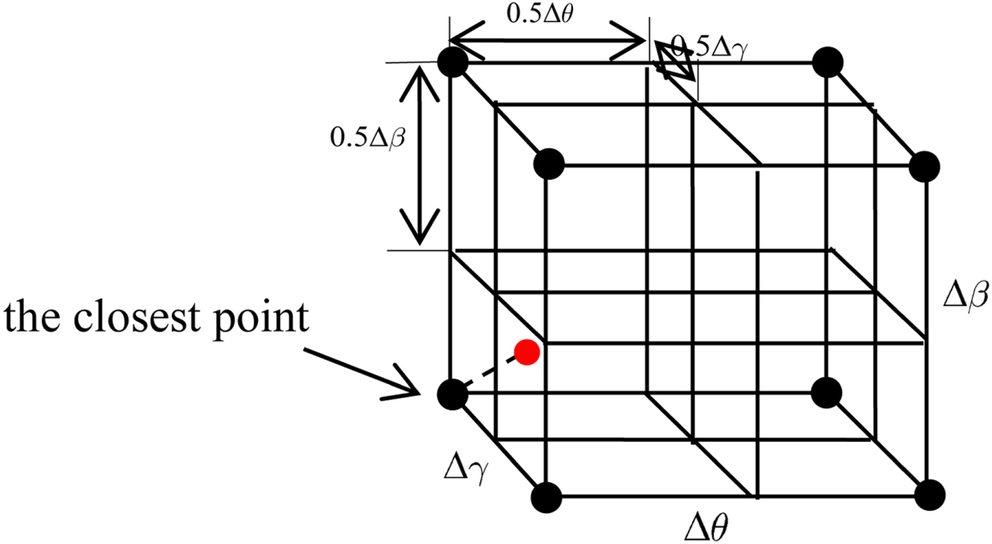
If a search technique is implemented in the attitude domain with a certain search step, the constant search space of attitude is transformed into a group of discrete searching points  $\lpar \bar{\theta}\comma \; \bar{\beta}\comma \; \bar{\gamma}\rpar $ (see Figure 4). The true attitude must be in a cube formed by the searching points. This cube is called here the “correct cube”, and there are eight search points which lie at the corners of the correct cube (see Figure 5). Assuming Δθ, Δ β, Δγ are the search steps of heading, pitch and roll, the size of the correct cube is Δθ × Δβ × Δγ, and it can be divided into eight small cubes which are of size 0 · 5Δθ × 0 · 5Δβ × 0 · 5Δγ. Each small cube has one search point, and the point which is closest to the true attitude is the search point corresponding to the small cube which contains the true attitude. This point is named here the “closest point” (see Figure 5), and it can be denoted as (θ + k 1Δθ, β + k 2Δβ, γ + k 3Δγ), where k 1, k 2, k 3 are the scale factors. No matter where the location of true attitude is, k 1, k 2, k 3 must satisfy |k 1| ≤ 0·5, |k 2| ≤ 0·5, |k 3| ≤ 0·5.
Illustration of transforming constant search space to discrete searching points. The cube in (a) is the constant search space of attitude and the black points in (b) are the search points after discretisation, and the red point is the true attitude.

Illustration of correct cube. The red point is the true attitude, the black points are the search points of the correct cube, and the correct cube can be divided into eight small cubes.

To ensure the closest point to determine the correct ambiguities through Equation (18), the ambiguity change caused by the closest point must be less than half one cycle, and this restriction can be expressed as:
 $$\left\Vert \displaystyle{{1}\over{\lambda}} {\bi B}_{ij} {\bi M}\lpar \theta + k_{1} \Delta \theta\comma \; \beta + k_{2} \Delta \beta\comma \; \gamma + k_{3} \Delta \gamma\rpar - \displaystyle{{1}\over{\lambda}} {\bi B}_{ij} {\bi M}\lpar \theta\comma \; \beta\comma \; \gamma\rpar \right\vert \leq 0{\cdot}5 $$
where (θ, β, γ) is the true attitude, i denotes the i-th baseline in the multi-antennae model, and j denotes the j-th DD observation equation of the i-th baseline.
It should be noted that when ξ ≤ 10°, cos(ξ) ≈ 1, sin(ξ) ≈ ξ. Assuming Δθ, Δ β, Δγ ≤ 10° one can derive the Equation as follows:
 $$\eqalign{&{\bi M}\lpar \theta + k_1 \Delta \theta\comma \; \beta + k_2 \Delta \beta\comma \; \gamma + k_3 \Delta \gamma\rpar - {\bi M}\lpar \theta\comma \; \beta\comma \; \gamma\rpar \cr & \quad = \displaystyle{{\partial {\bi M} \lpar \theta\comma \; \beta\comma \; \gamma\rpar }\over{\partial \theta}} k_1 \Delta \theta + \displaystyle{{\partial {\bi M}\lpar \theta\comma \; \beta\comma \; \gamma\rpar }\over{\partial \beta}} k_2 \Delta \beta + \displaystyle{{\partial {\bi M}\lpar \theta\comma \; \beta\comma \; \gamma\rpar }\over{\partial \gamma}} k_3 \Delta \gamma} $$
By substituting Equation (20) into Equation (19), this restriction of search step Equation (19) can be rewritten as:
 $$\left\vert {\bi B}_{ij} \displaystyle{{\partial {\bi M}\lpar \theta\comma \; \beta\comma \; \gamma\rpar }\over{\partial \theta}} k_1 \Delta \theta + {\bi B}_{ij} \displaystyle{{\partial {\bi M} \lpar \theta\comma \; \beta\comma \; \gamma\rpar }\over{\partial \beta}} k_2 \Delta \beta + {\bi B}_{ij} \displaystyle{{\partial {\bi M} \lpar \theta\comma \; \beta\comma \; \gamma\rpar }\over{\partial \gamma}} k_3 \Delta \gamma\right\vert \leq 0{\cdot}5 \lambda $$
If one calculates search step Δθ, Δβ Δγ as Equation (22), restriction Equation (21) can be satisfied absolutely.
 $$\eqalign{& \Delta \theta \leq \displaystyle{{1}\over{\max \left(\left\Vert {\bi B}_{ij} \displaystyle{{\partial {\bi M}\lpar \theta\comma \; \beta\comma \; \gamma\rpar }\over{\partial \theta}}\right\Vert_{2}\right)}} \displaystyle{{0{\cdot}5 \lambda}\over{3 \vert k_1\vert}} \quad \Delta \beta \leq \displaystyle{{1}\over{\max \left(\left\Vert {\bi B}_{ij} \displaystyle{{\partial {\bi M}\lpar \theta\comma \; \beta\comma \; \gamma\rpar }\over{\partial \beta}}\right\Vert_{2}\right)}} \displaystyle{{0{\cdot}5 \lambda}\over{3 \vert k_2\vert}} \cr & \Delta \gamma \leq \displaystyle{{1}\over{\max \left(\left\Vert {\bi B}_{ij} \displaystyle{{\partial {\bi M}\lpar \theta\comma \; \beta\comma \; \gamma\rpar }\over{\partial \gamma}}\right\Vert_{2}\right)}} \displaystyle{{0{\cdot}5 \lambda}\over{3 \vert k_3\vert}}} $$
where max(•) means to get the maximum from a discrete series, and i = 1, 2···n; j = 1, 2···t.
Due to |k 1| ≤ 0·5, |k 2| ≤ 0·5, |k 3| ≤ 0·5, a tighter upper-limit of search step can be derived as:
 $$\eqalign{& \Delta \theta \leq \displaystyle{{\lambda/3}\over{\max \left(\left\Vert {\bi B}_{ij} \displaystyle{{\partial {\bi M}\lpar \theta\comma \; \beta\comma \; \gamma\rpar }\over{\partial \theta}}\right\Vert_{2}\right)}} \quad \Delta \beta \leq \displaystyle{{\lambda/3}\over{\max \left(\left\Vert {\bi B}_{ij} \displaystyle{{\partial {\bi M}\lpar \theta\comma \; \beta\comma \; \gamma\rpar }\over{\partial \beta}}\right\Vert_{2}\right)}} \cr & \Delta \gamma \leq \displaystyle{{\lambda/3}\over{\max \left(\left\Vert {\bi B}_{ij} \displaystyle{{\partial {\bi M}\lpar \theta\comma \; \beta\comma \; \gamma\rpar }\over{\partial \gamma}}\right\Vert_{2}\right)}}} $$
Unfortunately, the true attitude angles are unknown, and one cannot directly calculate the search step through Equation (23), but the tight a priori information of pitch and roll can help us to evaluate the upper-limit of search step Equation (23).
Taking Δθ for example,  $\displaystyle{{\partial {\bi M} \lpar \theta\comma \; \beta\comma \; \gamma\rpar }\over{\partial \theta}}$ can be rewritten as:
 $$\displaystyle{{\partial {\bi M}\lpar \theta\comma \; \beta\comma \; \gamma\rpar }\over{\partial \theta}} = {\bi U}\lpar \beta\comma \; \gamma\rpar \left[\matrix{ \sin \theta \cr \cos \theta }\right]$$
with:
 $${\bi U}\lpar \beta\comma \; \gamma\rpar = \left[\matrix{ 0 &-\cos \beta &0 &-\cos \gamma &-\sin \beta \sin \gamma &0 &\sin \gamma &-\sin \beta \cos \gamma &0 \cr \cos \beta &0 &0 &\sin \beta \sin \gamma &-\cos \gamma &0 &\sin \beta \cos \gamma &\sin \gamma &0 }\right]^{T} $$
Assuming ε β, ε γ are the error of  $\hat{\beta}$,
 $\hat{\gamma}$, and |ε β| ≤ 5°, |ε γ| ≤ 5°, similarly to Equation (20), U(β, γ) can be rewritten as:
 $${\bi U}\lpar \beta\comma \; \gamma\rpar = {\bi U}\lpar \hat{\beta}\comma \; \hat{\gamma}\rpar + \left.\displaystyle{{\partial {\bi U}\lpar \beta\comma \; \gamma\rpar }\over{\partial \beta}}\right\vert_{\beta = \hat{\beta}\comma \gamma = \hat{\gamma}} \varepsilon_{\beta} + \left.\displaystyle{{\partial {\bi U}\lpar \beta\comma \; \gamma\rpar }\over{\partial \gamma}}\right\vert_{\beta = \hat{\beta}\comma \gamma = \hat{\gamma}} \varepsilon_{\gamma} $$
where  $\hat{\beta}$,
 $\hat{\gamma}$ are a priori measurements of pitch and roll.
Due to  $\left\Vert\left[\matrix{ \sin \theta \cr \cos \theta}\right]\right\Vert_{2} = 1$, inequality Equation (27) can be derived by using norm theory:
 $$\left\Vert {\bi B}_{ij} \displaystyle{{\partial {\bi M} \lpar \theta\comma \; \beta\comma \; \gamma\rpar }\over{\partial \theta}}\right\Vert_{2} \leq \Vert {\bi B}_{ij} {\bi U}\lpar \hat{\beta}\comma \; \hat{\gamma}\rpar \Vert _{2} + \left\Vert\left[\matrix{ \varepsilon_{\beta} \cr \varepsilon_{\gamma} }\right]\right\Vert_2 \left\Vert\left[\matrix{ {\bi U}_1^T {\bi B}_{ij}^{T} &{\bi U}_{2}^{T} {\bi B}_{ij}^{T} }\right]\right\Vert_2 $$
where:  ${\bi U}_{1} = \left.\displaystyle{{\partial {\bi U}\lpar \beta\comma \; \gamma\rpar }\over{\partial \beta}}\right\vert_{\beta = \hat{\beta}\comma \gamma = \hat{\gamma}}$,
 ${\bi U}_{2} = \left.\displaystyle{{\partial {\bi U}\lpar \beta\comma \; \gamma\rpar }\over{\partial \gamma}}\right\vert_{\beta = \hat{\beta}\comma \gamma = \hat{\gamma}}$ and one makes use of the norm theory ‖AB‖2 ≤ ‖A‖2‖B‖2, ‖A + B‖2 ≤ ‖A‖2 + ‖B‖2.
Assuming,  $J_{ij}^{\theta} = \Vert {\bi B}_{ij} {\bi U}\lpar \hat{\beta}\comma \; \hat{\gamma}\rpar \Vert _{2} + \left\Vert\left[\matrix{ \varepsilon_{\beta} \cr \varepsilon_{\gamma} }\right]\right\Vert_{2} \left\Vert\left[\matrix{ {\bi U}_{1}^{T} {\bi B}_{ij}^{T} &U_{2}^{T} {\bi B}_{ij}^{T}}\right]\right\Vert_{2}$, the upper-limit of Δθ can be rewritten as:
 $$\Delta \theta \leq \displaystyle{{1}\over{\max \lpar J_{ij}^{\theta}\rpar }} \displaystyle{{\lambda}\over{3}}\quad \lpar i = 1\comma \; 2\comma \; \cdots n\semicolon \; j = 1\comma \; 2\comma \; \cdots t\rpar $$
Similarly, the upper-limit of Δ β, Δγ can be derived as follows (detail in the Appendix).
 $$\Delta \beta \leq \displaystyle{{1}\over{\max \lpar J_{ij}^{\beta}\rpar }} \displaystyle{{\lambda}\over{3}} \quad \Delta \gamma \leq \displaystyle{{1}\over{\max \lpar J_{ij}^{\gamma}\rpar }} \displaystyle{{\lambda}\over{3}} \lpar i = 1\comma \; 2 \cdots n\semicolon \; j = 1\comma \; 2 \cdots t\rpar $$
With the upper-limit of ε β, ε γ, the search step of attitude angle according to Equations (28) and (29) can be calculated, and then the search grids in the search space of attitude can be established. All the integer ambiguity candidates can be determined by the search points through Equation (18).
4.3. Modified strategy to fix ambiguities
After determining all the integer ambiguity candidates, the principle of total least-squares is used to fix the correct ambiguities. The objective function can be expressed as:
 $$\eqalign{{\bi H}\lpar {\bi N}\comma \; {\mathop{\bi M} \limits^{\smile}}\rpar &= \Vert {\brPhi} - {\bi B}{\mathop{\bi M} \limits^{\smile}}/\lambda - {\bi N}\Vert _{Q_{\phi}}^{2} + \Vert {\bi P} - {\bi B}{\mathop{\bi M} \limits^{\smile}}\Vert _{Q_P}^{2} + \displaystyle{{\Vert {\mathop{\beta} \limits^{\smile}} - \hat{\beta}\Vert^{2}}\over{\sigma_{\beta}^{2}}} \cr & \quad + \displaystyle{{\Vert {\mathop{\gamma} \limits^{\smile}} - \hat{\gamma}\Vert^{2}}\over{\sigma_{\gamma}^{2}}} {\bi Q}_{\Phi} \in {\open R}^{nt \times nt}\comma \; {\bi Q}_{P} \in {\open R}^{nt \times nt}} $$
with:
 $${\mathop{\bi M} \limits^{\smile}} = {\bi vec}\lpar \hbox{arg}\ \mathop{\min}\limits_{R \in {\open O}^{3 \times 3}} {\bi H}\lpar {\bi N}\comma \; {\bi vec}\lpar {\bi R}\rpar \rpar \rpar $$
where Qϕ, QP are the v-c matrices of Φ, P respectively.
Generally, the iteration should be involved in solving the nonlinear least-squares problem Equation (31), and it decreases the efficiency of computation.
To improve efficiency, in this section, we propose a non-iterative approximation method to simplify the iteration in calculating the objective function. The objective function Equation (30) can be parameterised with an attitude angle as:
 $${\bi H}\lpar {\bi N}\comma \; {\mathop{\bieta} \limits^{\smile}}\lpar {\bi N}\rpar \rpar = \Vert {\bi L} - {\bi F}\lpar {\bi N}\comma \; {\mathop{\bieta} \limits^{\smile}}\lpar {\bi N}\rpar \rpar \Vert_{Q}^{2} $$
with:
 $${\mathop{\bieta} \limits^{\smile}}\lpar {\bi N}\rpar = \hbox{arg}\, \mathop{\min}\limits_{\eta} \Vert {\bi L} - {\bi F}\lpar N\comma \; {\bieta}\rpar \Vert_{Q}^{2} $$
where  ${\bi F} \lpar {\bi N}\comma \; {\bieta}\rpar = {\bi vec}\left(\left[\matrix{ {\bi BM}\lpar \theta\comma \; \beta\comma \; \gamma\rpar /\lambda + N &{\bi BM}\lpar \theta\comma \; \beta\comma \; \gamma\rpar &\beta &\gamma}\right]\right)$,
 ${\bi Q} = diag\lpar {\bi Q}_{\Phi}\comma \; {\bi Q}_{P}\comma \; \sigma_{\beta}^{2}\comma \; \sigma_{\gamma}^{2}\rpar $,
 ${\bieta} = \left[\matrix{ \theta &\beta &\gamma }\right]^{T} \quad {\bi L} = {\bi vec}\left(\left[\matrix{ {\brPhi} &{\bi P} & \hat{\beta} &\hat{\gamma} }\right]\right)$.
By the parameterisation, the nonlinear constrained least-squares Equation (31) is transformed into nonlinear unconstrained least-squares Equation (33).
In theory, solving Equation (33) still involves the iteration, but if the initial value is close enough to η(N), an analytical and approximate solution of η(N) can be derived through least squares estimation.
For every candidate N, the orthogonal constraint of R is disregarded and the linear least-squares solution M0(N) is derived by a DD phase observation equation, and the rough attitude solution η0(N) is calculated by Equation (5).
For the correct candidate, considering the high precision of carrier phase measurement, η0(N) must be close enough to  ${\mathop{\bieta} \limits^{\smile}}\lpar N\rpar $ (for example, assuming the baseline length is 1 m and the error of relative position is less than 10 cm, the deviation of attitude is less than 5° or 0·1 radian), and F(N, η) can be linearized as follows:
 $${\bi L} = {\bi F}\lpar {\bi N}\comma \; {\bieta}\rpar = {\bi F}\lpar {\bi N}\comma \; {\bieta}_{0} \lpar {\bi N}\rpar \rpar + {\bi K} \Delta {\bieta}\lpar {\bi N}\rpar $$
where the high-order error has been neglected and  $\Delta {\bieta} \lpar {\bi N}\rpar = \bar{{\bieta}}\lpar {\bi N}\rpar - {\bieta}_{0} \lpar {\bi N}\rpar $,
 ${\bi K} = \left.\left(\displaystyle{{\partial {\bi F}}\over{\partial {\bieta}}}\right)^{T}\right\vert_{{\bieta} = {\bieta}_{0} \lpar {\bi N}\rpar }$.
Then  $\bar{{\bieta}}\lpar {\bi N}\rpar $ can be calculated as:
 $$\bar{{\bieta}} \lpar {\bi N}\rpar = {\bieta}_{0}\lpar {\bi N}\rpar + \lpar {\bi K}^{T} {\bi Q}^{-1} {\bi K}\rpar ^{-1} {\bi K}^{T} {\bi Q}^{-1} \lpar {\bi L} - {\bi F}\lpar {\bi N}\comma \; {\bieta}_0 \lpar {\bi N}\rpar \rpar \rpar $$
Due to only small errors,  $\bar{{\bieta}}\lpar {\bi N}\rpar $ is the approximate solution of
 ${\mathop{\bieta} \limits^{\smile}}\lpar {\bi N}\rpar $, and the value of
 ${\bi H}\lpar {\bi N}\comma \; \bar{{\bieta}} \lpar {\bi N}\rpar \rpar $ is nearly equal to
 ${\bi H}\lpar {\bi N}\comma \; {\mathop{\bieta} \limits^{\smile}} \lpar {\bi N}\rpar \rpar $,
 ${\bi H}\lpar {\bi N}\comma \; {\mathop{\bieta} \limits^{\smile}} \lpar {\bi N}\rpar \rpar \approx {\bi H}\lpar {\bi N}\comma \; \bar{{\bieta}} \lpar {\bi N}\rpar \rpar $.
For the incorrect ambiguity candidates, Equation (35) is still used to calculate  $\bar{{\bieta}} \lpar {\bi N}\rpar $, but because of the larger error caused by the incorrect integer ambiguities,
 $\bar{{\bieta}}\lpar {\bi N}\rpar $ is no longer the approximate solution of
 ${\mathop{\bieta} \limits^{\smile}} \lpar {\bi N}\rpar $. It should be noted that
 ${\mathop{\bieta} \limits^{\smile}}\lpar {\bi N}\rpar $ is the least-squares solution for Equation (33), and the objective function value of
 ${\mathop{\bieta} \limits^{\smile}} \lpar {\bi N}\rpar $ is minimal. Thus, the value of
 ${\bi H}\lpar {\bi N}\comma \; \bar{{\bieta}} \lpar {\bi N}\rpar \rpar $ is equal to or greater than
 ${\bi H}\lpar {\bi N}\comma \; {\mathop{\bieta} \limits^{\smile}} \lpar {\bi N}\rpar \rpar $,
 ${\bi H}\lpar {\bi N}\comma \; {\mathop{\bieta} \limits^{\smile}} \lpar {\bi N}\rpar \rpar \leq {\bi H}\lpar {\bi N}\comma \; \bar{{\bieta}} \lpar {\bi N}\rpar \rpar $.
As analysed above, the value  ${\bi H}\lpar {\bi N}\comma \; \bar{{\bieta}} \lpar {\bi N}\rpar \rpar $ of correct ambiguities is still minimal and correct ambiguities can be still fixed by minimising Equation (32) with
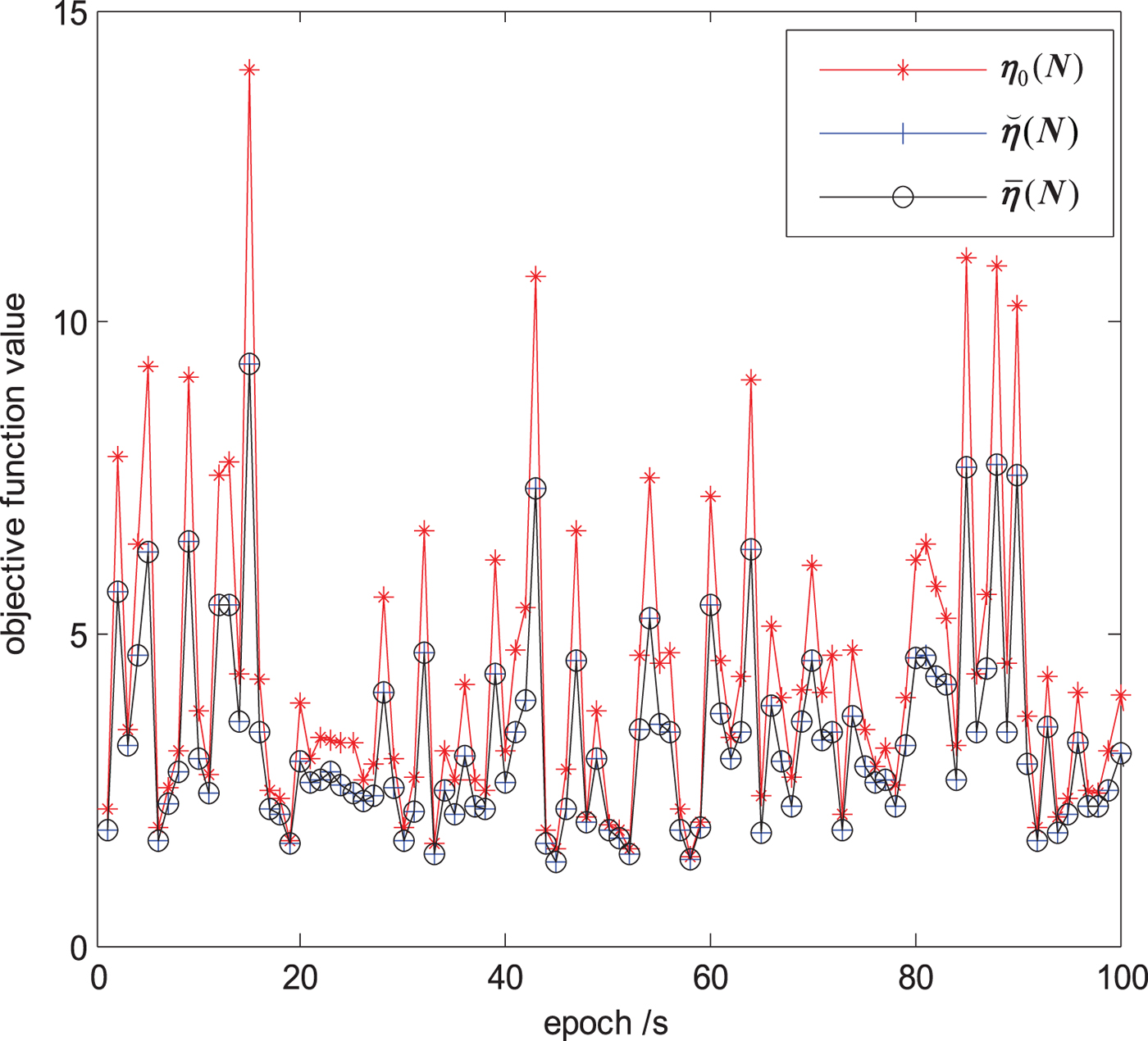
 $\bar{{\bieta}}\lpar {\bi N}\rpar $. Figure 6 shows the objective function value of the correct ambiguities for the first 100 epoch data of the static test described in Section 5 calculated from η0(N),
 ${\mathop{\bieta} \limits^{\smile}} \lpar {\bi N}\rpar $ and
 $\bar{{\bieta}}\lpar {\bi N}\rpar $.
The value of the objective function calculated from η(N),  $\mathop{{\bieta}}\limits^{\smile}\lpar {\bi N}\rpar $ and
 ${\bar{\bieta}}\lpar {\bi N}\rpar$.

As shown in Figure 6, the objective function value calculated from  $\bar{{\bieta}} \lpar {\bi N}\rpar $ Equation (35) is nearly equal to that of
 ${\mathop{\bieta} \limits^{\smile}} \lpar {\bi N}\rpar $. This means that
 $\bar{{\bieta}}\lpar {\bi N}\rpar $ has an equal performance to
 ${\mathop{\bieta} \limits^{\smile}} \lpar {\bi N}\rpar $ in fixing the ambiguity candidate, but is more efficient than
 ${\mathop{\bieta} \limits^{\smile}} \lpar {\bi N}\rpar $, because of the simplification of iteration in Equation (33).
The steps of our new method are then as follows:
Step 1: Determine the search step and region and establish the search grids.
1. Make use of a priori information of pitch and roll to determine the attitude search region. The search space of attitude is heading ± 180°, pitch
 $\hat{\beta} + 5\sigma_{\beta}$, roll $\hat{\gamma} \pm 5 \sigma_{\gamma}$.
2. Compute the attitude search step Δθ, Δ β, Δγ according to Equations (28) and (29), establish the search grids in the search space with Δθ, Δ β, Δγ, and find all the search points
$\lpar \bar{\theta}\comma \; \bar{\beta}\comma \; \bar{\gamma}\rpar $ in the search space.
Step 2: Determine all the ambiguity candidates and calculate the objective function.
1. Make use of all the search points
$\lpar \bar{\theta}\comma \; \bar{\beta}\comma \; \bar{\gamma}\rpar $ to determine the integer ambiguity candidates through Equation (18).2. Calculate
${\bieta}_{0}\lpar {\bi N}\rpar \comma \; \bar{{\bieta}}\lpar {\bi N}\rpar $ for every candidate, and substitute $\bar{{\bieta}}\lpar {\bi N}\rpar $ for ${\mathop{\bieta} \limits^{\smile}}\lpar {\bi N}\rpar $ to evaluate the objective function value Equation (32).
Step 3: Select one candidate N that returns the smallest value for the objective function as a fixed solution.


As long as the ambiguity candidate is fixed, the final high precision attitude can be derived by solving the non-linear least squares Equation (33).
5. TEST VERIFICATION AND ANALYSIS
In order to test the performance of the method proposed in this paper, static and dynamic experiments were carried out on 23 June 2017 and 17 January 2018 respectively in Xi'an, China, with a 10° cut off elevation angle.
5.1. Static experiment
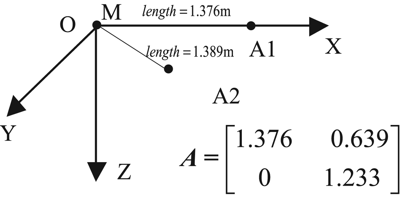
In the static experiment, three NovAtel OEM628 (NovAtel Inc, Calgary, Canada) receivers were used to collect frequency L1 carrier phase data and Coarse/Acquisition (C/A) code data with a sampling interval of 1 s, which can provide measurement precision of about 2 mm (1σ) for L1 carrier phase and about 20 cm (1σ) for C/A code measurement. Three NovAtel 702-GGG antennae were mounted on the roof of the scientific research building. Data was recorded from 23 June 2017 to 24 June 2017 for 63,488 s. The two baselines were 1·389 m and 1·376 m long, forming an angle of 62 · 603°. Their coordinates in the body frame are shown in Figure 7.
The antennae step-up and the relative placement: O-XYZ is the body frame and M is the main antenna, A1 and A2 are the auxiliary antennae.

The data collected was post processed using Matlab 2010a, and the computer used had an AMD Athlon(tm) X2 215 processor running at 2·70 GHz with 2 GB RAM. The accurate attitude of the baselines in the ENU frame was heading 214 · 951°, pitch 3 · 076° and roll 0 · 374°. In order to simulate the a priori information of pitch and roll obtained by other sensors, we added white Gaussian distribution noise with zero mean to the true value and set its standard deviation to 1°. The attitude search space was heading ± 180°, pitch ±5° and roll ±5°.
The integer ambiguity vector was resolved at every epoch. We compared our new method with two methods based on search techniques in the ambiguity domain as follows. True ambiguities for every epoch were solved by using the accurate baselines attitude.
Method 1: Standard MC-LAMBDA method without considering any angular a priori information.
Method 2: Modified MC-LAMBDA method which integrates the a priori information of pitch and roll into the objective function.
A non-ellipsoidal search strategy (Giorgi and Teunissen, Reference Giorgi and Teunissen2010) was applied in the search process of these two methods.
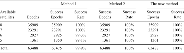
Table 1 shows the success rate for each method as a function of the number of satellites available. Due to considering only the baselines configuration constraint, the success rate of method 1 begins to decrease when the number of available satellites is less than six, and it gets the ambiguity resolution wrong in over 10 epochs. In contrast from method 1, method 2 and this paper's new method consider not only the baselines configuration constraint but also a priori information of pitch and roll to strengthen the model of GNSS attitude determination and achieve a success rate of 100% in the experiments, even when only five satellites are available.
Success rate comparison for three methods as a function of the number of satellites available

The average time that was required for resolving integer ambiguities was measured using Matlab 2010a (see Table 2). The number of ambiguity candidates for the three methods and the number of pseudo candidates are reported in Table 2.
Average computation time and average number of ambiguity candidates for the three methods

As shown, the efficiency of the standard MC-LAMBDA (method 1) is excellent when utilising a non-ellipsoidal search strategy, and the average number of pseudo candidates is only 13. When the a priori information of pitch and roll is integrated into the objective function (method 2), the efficiency of MC-LAMBDA becomes worse. On average, there are over 1,000 pseudo candidates. The average computation time of method 2 is about 0·5 s. In contrast to the search technique in the ambiguity domain, a priori information of attitude angle is used to compress the search space directly in our new method. The average number of candidates is not too high. Due to fewer candidates and the non-iterative approximate method which simplified the evaluation in Equation (33), our new method is a little slower than method 1, but much faster than method 2. The average computation time of our new method is less than 0·1 s.
In order to test how the noise level of pitch and roll affects the performance of our method, we set different Standard Deviations (STD) for pitch and roll and measured the average computation time of method 2 and our new method. The attitude search space was still heading ± 180°, pitch ± 5σ β and roll ± 5σ γ. As shown in Table 3, when increasing the noise level, the efficiency of method 2 clearly improves, while the performance of our new method becomes worse. Pitch and roll provided by a MEMS-IMU/GNSS integrated navigation system is fairly accurate, and σ β, σ r are generally less than 2°. Under these conditions, the new method still performs better than method 2.
Average computation time at different noise levels

5.2. Dynamic test
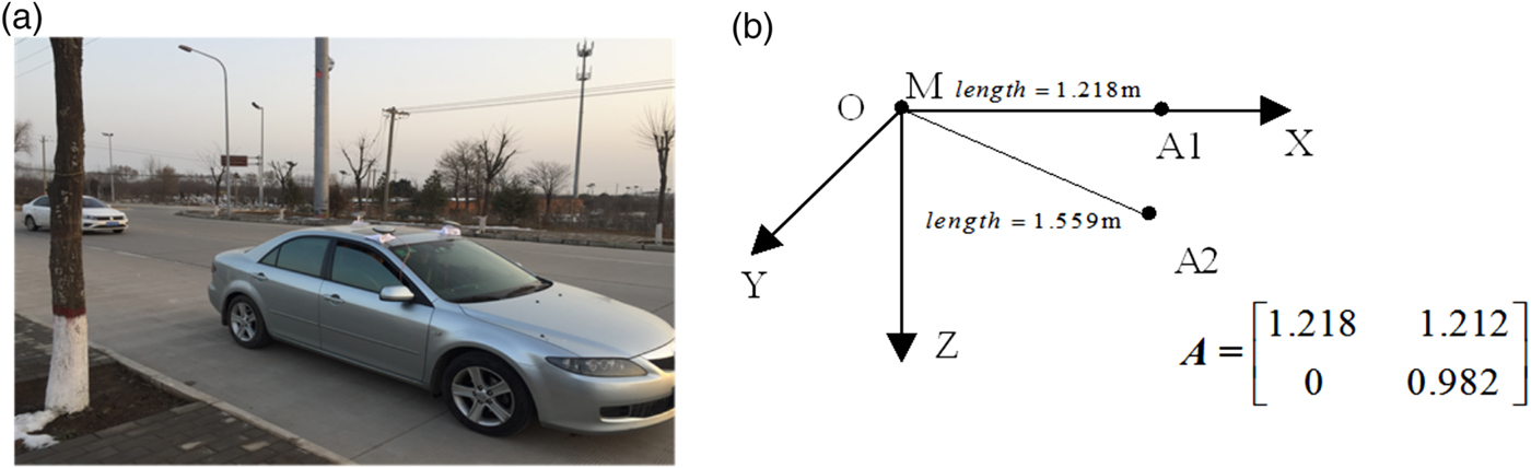
The dynamic test took place on 17 January 2018, in the west of Xi'an. Three NovAtel 702-GGG antennae were placed on the roof of the experimental vehicle (see Figure 8(a)). The two antennae at the front were connected to two NovAtel OEM628 receivers and the antenna at the back was connected to a NovAtel SPAN-CPT single Enclosure GNSS/Inertial Navigation System (INS) Receiver which can provide the original measurements of Global Positioning System (GPS) and a priori information of pitch and roll through integration (the standard deviation is pitch 0 · 02° and roll 0 · 02°). Carrier phase data of frequency L1 and C/A code data was collected with a sampling interval of 1 s. During the first 335 s, the experimental vehicle stood still to calibrate the alignment error of the INS. The two baselines' coordinates in the body frame are shown in Figure 8(b).
Dynamic experimental scene and the antennae set-up: O-XYZ is the body frame and M, A1 and A2 are the main and the auxiliary antennae.

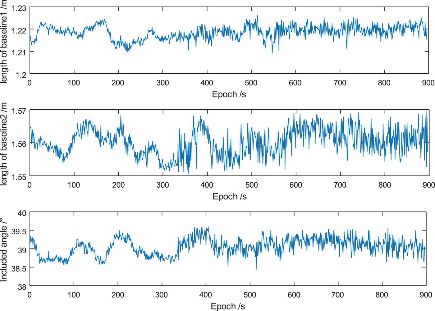
The collected data was processed with three methods as for the static test. The length and the included angle of the two baselines were used to check whether the integer ambiguities were fixed correctly. The single-epoch success rate and the average time consumption are reported in Table 4. Due to the higher noise levels (than the static test), without a priori information of pitch and roll (method 1), the MC-LAMBDA method is not capable of providing the correct ambiguities from a single-epoch set of observations for more than 90% of the time, whereas the additional a priori information improves the fixing rate of MC-LAMBDA and our new method. 100% of the epochs were correctly resolved. Comparing the average computation time, the new method is still much faster than method 2, and much shorter than 0·1 s. The average computation time for method 2 is more than 0·5 s, and its real-time performance is the worst. The results are consistent with the static test.
The single-epoch success rate and average computation time

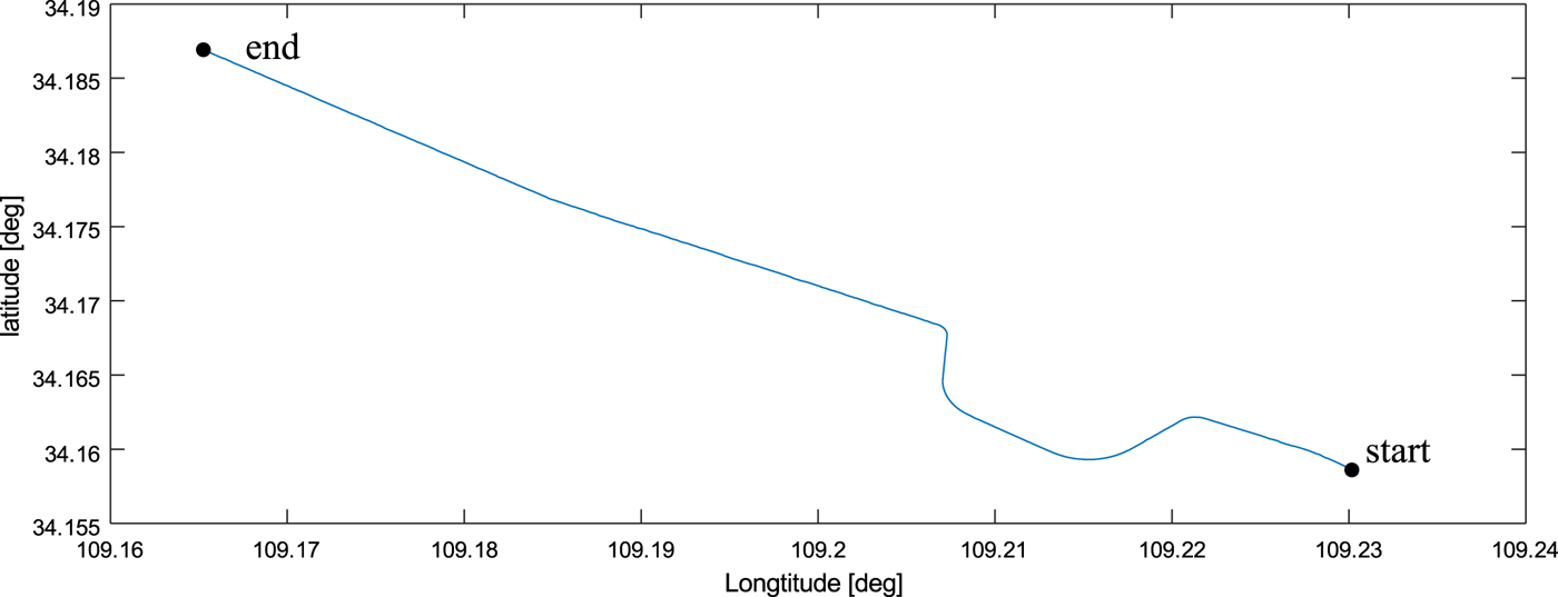
The trajectory of the experimental vehicle is shown in Figure 9; this was obtained by antenna pseudo-range positioning,
The trajectory of the dynamic test.

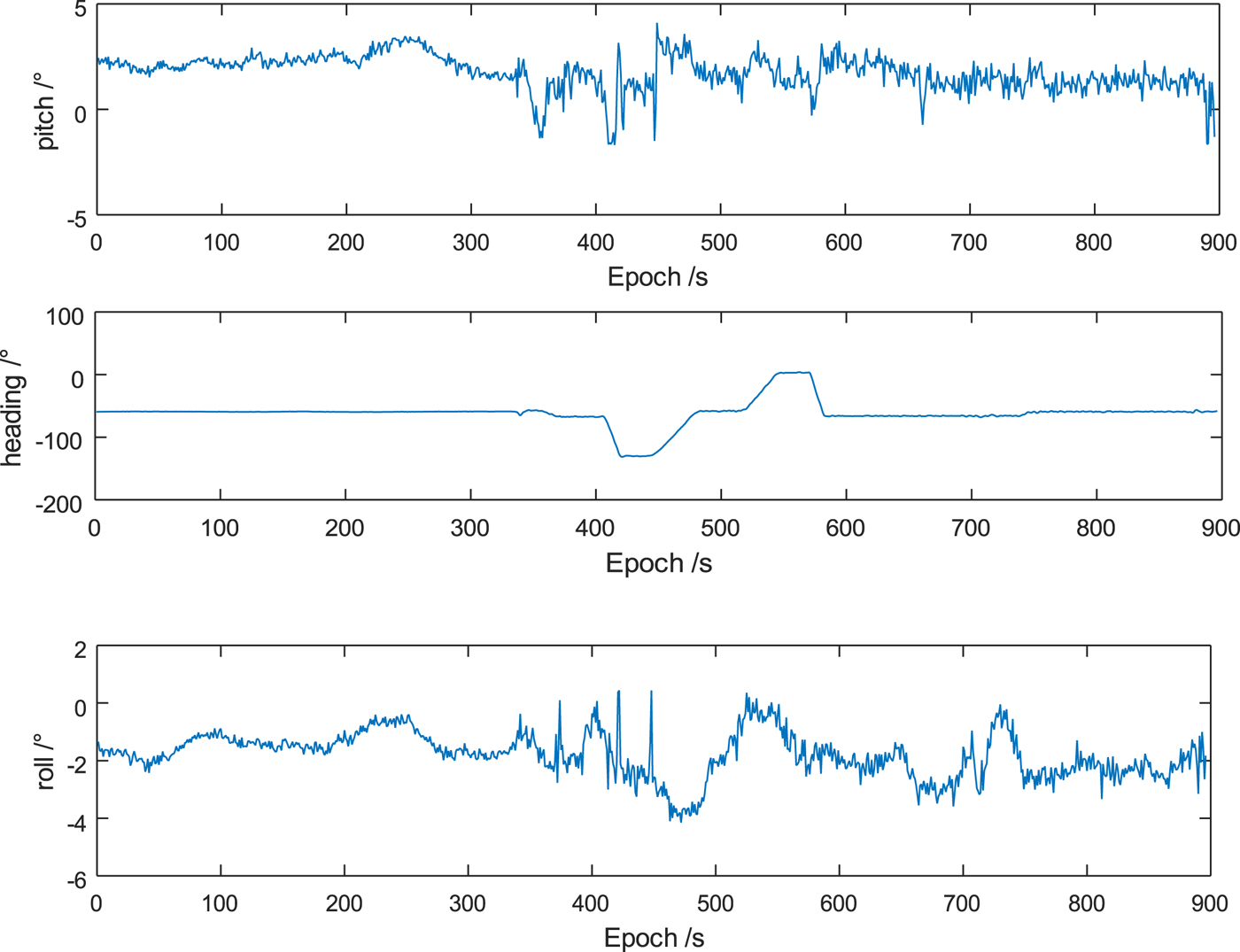
The baseline and attitude results resolved by our method are shown in Figure 10 and Figure 11.
The length and included angle of baselines estimated via GNSS.

The attitude angle estimated via GNSS.

Figure 10 shows that the length and included angle of the two baselines are measured as 1·218 m, 1·560 m and 39 · 04°, which corresponds to the a priori information; Figure 11 shows that when moving, heading changes correspond to the vehicle moving track, the pitch is about 2°, the roll is about −2° and the maximum floating value is about 2° corresponding to the uneven ground. The experiment result indicates that length and included angle of the two baselines, and full attitude of the vehicle were all measured correctly, which is due to the correctly fixed ambiguities.
6. CONCLUSIONS
This paper fully considers the a priori information of baselines configuration, pitch and roll. Based on a search technique in the attitude domain, a fast and reliable new method for full attitude determination is proposed.
In contrast to more conventional search techniques, this paper's new method performs a search procedure in the attitude domain and the ambiguity candidates are sought in a constant three-dimensional attitude domain with an analytic search step. Angular a priori information was used to compress the search space and avoid a large number of pseudo candidates and a non-iterative method is presented to simplify the computation of nonlinear least squares problems caused by the nonlinear a priori information. Experimental results show that the new method can achieve a very high success rate and high efficiency. A final dynamic vehicle experiment further verifies the reliability of this new method.
Although the good performance of the new method has been demonstrated, it is still necessary to validate our new method through a dynamic test with an accurate attitude reference. In addition, the pseudorange is not considered in the search process of our new method. In the absence of any a priori attitude information, the search space will be very large, and the real-time performance of our new method will decrease dramatically. How to make use of pseudorange to improve our method will be a focus in further research.
FINANCIAL SUPPORT
This work is supported by National Natural Science Foundation of China (Grant No. 61601506).
APPENDIX
DERIVATION OF THE UPPER LIMIT OF SEARCH STEP OF PITCH AND ROLL
We introduce the matrix as follows:
 $${\bi D}\lpar \beta\comma \; \gamma\rpar = \left[\matrix{ -\sin \beta &0 &0 &\cos \beta \sin \gamma &0 &0 &\cos \beta \cos \gamma &0 &0 \cr 0 &-\sin \beta &0 &0 &\cos \beta \sin \gamma &0 &0 &\cos \beta \cos \gamma &0 }\right]^{T} $$
 $${\bi D}^{\prime} \lpar \beta\comma \; \gamma\rpar = \left[\matrix{ 0 &0 &\cos\beta &0 &0 &\sin \beta \sin \gamma &0 &0 &\sin \beta \cos \gamma }\right]^{T} $$
and  $\displaystyle{{\partial {\bi M}\lpar \theta\comma \; \beta\comma \; \gamma\rpar }\over{\partial \beta}}$ can be rewritten as:
 $$\displaystyle{{\partial {\bi M}\lpar \theta\comma \; \beta\comma \; \gamma\rpar }\over{\partial \beta}} = {\bi D} \lpar \beta\comma \; \gamma\rpar \left[\matrix{\sin \theta \cr \cos \theta }\right]+ {\bi D}^{\prime}. $$
As for Equation (22), we can derive Equation (A4) as
 $$\eqalign{\left\Vert {\bi B}_{ij} \displaystyle{{\partial {\bi M} \lpar \theta\comma \; \beta\comma \; \gamma\rpar }\over{\partial \beta}}\right\Vert_{2} & \leq \Vert {\bi B}_{ij} {\bi D}\lpar \hat{\beta}\comma \; \hat{\gamma}\rpar \Vert _{2} + \Vert {\bi B}_{ij} {\bi D}^{\prime}\lpar \hat{\beta}\comma \; \hat{\gamma}\rpar \Vert _{2} + \left\Vert\left[\matrix{ \varepsilon_{\beta} \cr \varepsilon_{\gamma} }\right]\right\Vert_{2} \left\Vert\left[\matrix{ {\bi D}_1^T {\bi B}_{ij}^{T} &{\bi D}_{2}^{T} {\bi B}_{ij}^{T} }\right]\right\Vert_{2} \cr & \quad + \left\Vert\left[\matrix{ \varepsilon_{\beta} \cr \varepsilon_{\gamma} }\right]\right\Vert_{2} \left\Vert\left[\matrix{ {\bi B}_{ij} {\bi D}_{1}^{\prime} &{\bi B}_{ij} {\bi D}_{2}^{\prime}}\right]\right\Vert_{2}} $$
where  ${\bi D}_{1} = \left.\displaystyle{{\partial {\bi D} \lpar \beta\comma \; \gamma\rpar }\over{\partial \beta}}\right\vert_{\beta = \hat{\beta}\comma \gamma = \hat{\gamma}}$,
 ${\bi D}_{2} = \left.\displaystyle{{\partial {\bi D} \lpar \beta\comma \; \gamma\rpar }\over{\partial \gamma}}\right\vert_{\beta = \hat{\beta}\comma \gamma = \hat{\gamma}}$,
 ${\bi D}_{1}^{\prime} = \left.\displaystyle{{\partial {\bi D}^{\prime} \lpar \beta\comma \; \gamma\rpar }\over{\partial \beta}}\right\vert_{\beta = \hat{\beta}\comma \gamma = \hat{\gamma}}$,
 ${\bi D}_{2}^{\prime} = \left.\displaystyle{{\partial {\bi D}^{\prime} \lpar \beta\comma \; \gamma\rpar }\over{\partial \gamma}}\right\vert_{\beta = \hat{\beta}\comma \gamma = \hat{\gamma}}$.
Assuming  $J_{ij}^{\beta} = \Vert {\bi B}_{ij} {\bi D}\lpar \hat{\beta}\comma \; \hat{\gamma}\rpar \Vert _{2} + \Vert {\bi B}_{ij} {\bi D}^{\prime} \lpar \hat{\beta}\comma \; \hat{\gamma}\rpar \Vert _{2} + \left\Vert\left[\matrix{ \varepsilon_{\beta} \cr \varepsilon_{\gamma} }\right]\right\Vert_{2} \left\Vert\left[\matrix{ {\bi D}_{1}^{T} {\bi B}_{ij}^{T} &{\bi D}_{2}^{T} {\bi B}_{ij}^{T} }\right]\right\Vert_{2} + \left\Vert\left[\matrix{ \varepsilon_{\beta} \cr \varepsilon_{\gamma} }\right]\right\Vert_{2} \left\Vert\left[\matrix{ {\bi B}_{ij} {\bi D}_{1}^{\prime} &{\bi B}_{ij} {\bi D}_{2}^{\prime} }\right]\right\Vert_{2}$, the upper limit of Δ β can be expressed as:
 $$\Delta \beta \leq \displaystyle{{1}\over{\max \lpar J_{ij}^{\beta}\rpar }} \displaystyle{{\lambda}\over{3}} \lpar i = 1\comma \; 2 \cdots n\colon j = 1\comma \; 2\comma \; ... t\rpar $$
Similarly, we introduce the matrix as follows:
 $${\bi E}\lpar \beta\comma \; \gamma\rpar = \left[\matrix{ 0 &0 &0 &\sin \beta \cos \gamma &\sin \gamma &0 &- \sin \beta \sin \gamma &\cos \gamma &0 \cr 0 &0 &0 &-\sin \gamma &\sin \beta \cos \gamma &0 &- \cos \gamma &- \sin \beta \sin \gamma &0 }\right]^{T} $$
 $${\bi E}^{\prime}\lpar \beta\comma \; \gamma\rpar = \left[\matrix{ 0 &0 &0 &0 &0 &- \cos \beta \cos \gamma &0 &0 &\cos \beta \sin \gamma }\right]^{T} $$
and  $\displaystyle{{\partial {\bi M}\lpar \theta\comma \; \beta\comma \; \gamma\rpar }\over{\partial \gamma}}$ can be rewritten as:
 $$\displaystyle{{\partial {\bi M}\lpar \theta\comma \; \beta\comma \; \gamma\rpar }\over{\partial \gamma}} = {\bi E}\lpar \beta\comma \; \gamma\rpar \left[\matrix{ \sin \theta \cr \cos \theta }\right]+ {\bi E}^{\prime}. $$
Thus, Equation (A9) can be derived:
 $$\eqalign{& \left\Vert {\bi B}_{ij} \displaystyle{{\partial {\bi M} \lpar \theta\comma \; \beta\comma \; \gamma\rpar }\over{\partial \gamma}}\right\Vert_{2} \leq \Vert {\bi B}_{ij} {\bi E}\lpar \hat{\beta}\comma \; \hat{\gamma}\rpar \Vert _{2} + \Vert {\bi B}_{ij} {\bi E}^{\prime}\lpar \hat{\beta}\comma \; \hat{\gamma}\rpar \Vert _{2} + \left\Vert\left[\matrix{ \varepsilon_{\beta} \cr \varepsilon_{\gamma} }\right]\right\Vert_{2} \left\Vert\left[\matrix{ {\bi E}_1^T {\bi B}_{ij}^{T} &{\bi E}_{2}^{T} {\bi B}_{ij}^{T} }\right]\right\Vert_{2} \cr & \quad + \left\Vert\left[\matrix{ \varepsilon_{\beta} \cr \varepsilon_{\gamma} }\right]\right\Vert_{2} \left\Vert\left[\matrix{ {\bi B}_{ij} {\bi E}_{1}^{\prime} &{\bi B}_{ij} {\bi E}_{2}^{\prime}}\right]\right\Vert_{2}}$$
where  ${\bi E}_{1} = \left.\displaystyle{{\partial {\bi E} \lpar \beta\comma \; \gamma\rpar }\over{\partial \beta}}\right\vert_{\beta = \hat{\beta}\comma \gamma = \hat{\gamma}}$,
 ${\bi E}_{2} = \left.\displaystyle{{\partial {\bi E} \lpar \beta\comma \; \gamma\rpar }\over{\partial \gamma}}\right\vert_{\beta = \hat{\beta}\comma \gamma = \hat{\gamma}}$,
 ${\bi E}_{1}^{\prime} = \left.\displaystyle{{\partial {\bi E}^{\prime} \lpar \beta\comma \; \gamma\rpar }\over{\partial \beta}}\right\vert_{\beta = \hat{\beta}\comma \gamma = \hat{\gamma}}$,
 ${\bi E}_{2}^{\prime} =\left.\displaystyle{{\partial {\bi E}^{\prime} \lpar \beta\comma \; \gamma\rpar }\over{\partial \gamma}}\right\vert_{\beta = \hat{\beta}\comma \gamma = \hat{\gamma}}$.
Assuming  $J_{ij}^{\gamma} = \Vert {\bi B}_{ij} {\bi E}\lpar \hat{\beta}\comma \; \hat{\gamma}\rpar \Vert _{2} + \Vert {\bi B}_{ij} {\bi E}^{\prime} \lpar \hat{\beta}\comma \; \hat{\gamma}\rpar \Vert _{2} + \left\Vert\left[\matrix{ \varepsilon_{\beta} \cr \varepsilon_{\gamma} }\right]\right\Vert_{2} \left\Vert\left[\matrix{ {\bi E}_{1}^{T} {\bi B}_{ij}^{T} &{\bi E}_{2}^{T} {\bi B}_{ij}^{T} }\right]\right\Vert_{2} +\break \left\Vert\left[\matrix{ \varepsilon_{\beta} \cr \varepsilon_{\gamma} }\right]\right\Vert_{2} \left\Vert\left[\matrix{ {\bi B}_{ij} {\bi E}_{1}^{\prime} &{\bi B}_{ij} {\bi E}_{2}^{\prime} }\right]\right\Vert_{2}$, the upper limit of Δγ can be expressed as:
 $$\Delta \gamma \leq \displaystyle{{1}\over{\max \lpar J_{ij}^{\gamma}\rpar }} \displaystyle{{\lambda}\over{3}} \lpar i = 1\comma \; 2 \cdots n\semicolon \; j = 1\comma \; 2 \cdots t\rpar $$