I. INTRODUCTION
The technology of energy self-sufficiency has received an increasing attention in the field of power supply [Reference Brown1] for wireless devices. Rectennas increase the lifetime of sensors’ network and minimize the energy impact of communication [Reference Gao2]. A rectenna usually consists of a receiving antenna and a rectifying circuit. It is capable of capturing the microwave energy from a surrounding environment and converting it into useful DC energy.
The existing high-efficiency rectennas are designed for high-power levels at industrial, scientific and medical (ISM) or global system for mobile communications (GSM) frequency bands [Reference Takhedmit3]. However, high-power densities are not available everywhere. For example, the received power from a base station is limited in order to respect health standards. Based on an ambient environment investigation, microwave power density is generally between 1 nW/cm2 [4] and 10 µW/cm2, typical maximum public exposure defined by the World Health Organization. But the conversion efficiency is low because of the diode behavior, at low-power levels. Only 0.7% rectifier conversion efficiency is obtained for around 4 µW/cm2 power density [Reference Bouchouicha, Latrach, Dupont and Ventura5]. Using broadband antenna, spatial frequency, and polarization diversity [Reference Hagerty, Helmbrecht, McCalpin, Zane and Popovic6], the efficiency is increased. In real configuration, the input signal is time variant and has a specific frequency band. Using real multiband signal coming from base stations, the radiofrequency (RF) ambient energy harvesting reaches same performance than other ambient energy-harvesting technologies [Reference Pinuela, Mitcheson and Lucyszyn7]. Moreover, in the real case, the orthogonal frequency division multiplexing (OFDM) modulation increases the efficiency in comparison with the single tone signal [Reference Collado and Georgiadis8].
In this paper, we focus on the rectenna efficiency, tested with a single tone signal. A monopole rectenna is proposed with a configuration of single serial Schottky diode. The antenna frequency response takes part in the improvement of the efficiency. The rectifier design is based on HSMS-2850 Schottky diode which is not the mostly used at 2.45 GHz ISM frequency band [Reference Pinuela, Mitcheson and Lucyszyn9], but this diode has a high responsivity. Using Agilent ADS (Advanced Design System), a rectifying circuit is designed for low-power level of −20 dBm. A printed monopole wideband antenna is also designed with Ansoft HFSS (High Frequency Structure Simulator) software. This rectenna may be used to supply sensors far away from power sources or to harvest energy from ambient environment.
II. DIODE RECTIFYING CIRCUIT
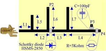
A rectifying circuit contains a serial diode, an output load resistor, and a capacitor parallel with the load, as presented in Fig. 1. The points P2, P3, and P4 are connected to the ground plane. In order to lead to a low-cost mass production, the circuit is printed on Bernier FR4 substrate with ɛ r = 4.3 and 1.58 mm thickness. The used diode is a commercial Schottky diode HSMS-2850 in a SOT23 package.
Configuration of the rectifying circuit.

The diode behavior is determined by its nonlinear zero bias resistor [Reference Hemour, Zhao and Lorenz10]. Few diodes are available for low-power rectifiers. To select a diode, the important parameters are its high saturation current, its small junction capacitance and its low threshold voltage. The HSMS-2850 diode has a high saturation current of 3 µA, a small zero-bias junction capacitance of 0.18 pF. Moreover, series resistance is not small, but it is similar to the other zero bias diodes. Despite the fact that this diode is recommended for frequency lower than 1.5 GHz, it shows more attractive parameters than the HSMS-2860 diode, previously tested for low-power levels, as proved in the simulated model by taking into account input mismatch [Reference Zhou, Froppier and Razban11]. Moreover, this diode is sensitive to a weak signal owing to a low threshold voltage of 0.15 V. We show that in single serial configuration, this diode is suitable for energy-harvesting applications at low-power densities in 2.45 GHz ISM band. However, because of a low-peak reverse voltage of 3.8 V, this diode must be maintained in low-power levels in order to protect it from breaking down.
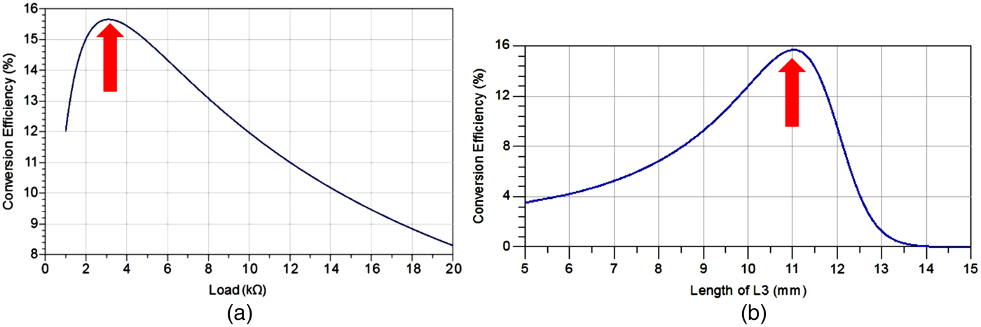
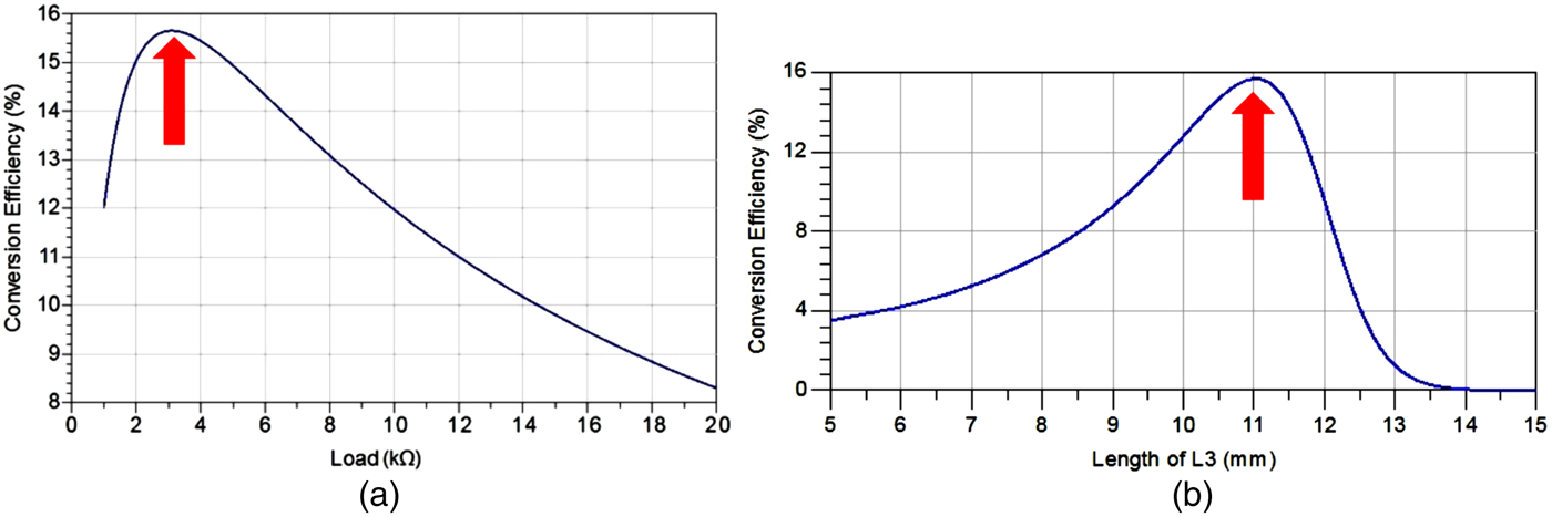
Using ADS harmonic balance simulation and large signal scattering parameter, a capacitor of 100 pF was chosen to obtain continuous DC signal. The maximum power transfer theorem and the DC modeling were used to find the optimal (Fig. 2(a)) load resistor of 3 kΩ for maximum efficiency. The lengths of the line and the stub (L2 and L5) of the matching circuit were also optimized for an incident power of −20 dBm at 2.45 GHz using “best conversion efficiency” criterion in ADS Hybrid optimization. A short stub L6 of quarter wavelength was proposed in the input of the diode to constitute a DC loop and to reject harmonic signals generated by the rectification process. A quarter wavelength open stub L7 acts as a low-pass filter to prevent harmonic signals from the load. Figure 2(b) shows the influence of the length L3 on the output harmonic rejection and so on the efficiency. Considering the open-end effect on a microstrip fringe and the equivalent inductance of a via-hole, some modeling methods improve the simulation accuracy.
DC load (a) and output filter (b) optimization. The red arrow indicates optimal point.
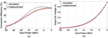
The circuits were measured using Rohde & Schwarz Vector Network Analyzer. The matching level was below −10 dB and the matching frequency is about 2.4 GHz with a narrow bandwidth. As seen in Fig. 3, the measured efficiency goes from 3 to 31% when the input power increases from Pin = −30 to 0 dBm.
Simulated and measured efficiency (a) and output voltage (b) versus incident power.

Good agreement is observed between simulation and measurement. Actually, the efficiency is 13.6% at −20 dBm with an output voltage of 64 mV. This good result was obtained without input RF filter required for better results. As it is shown in Section IV, this function will be taken in charge by the antenna.
III. MONOPOLE RECTENNA
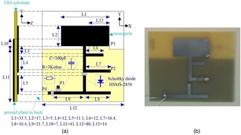
The proposed monopole rectenna is illustrated in Fig. 4. A rectangular monopole and a rectifying circuit are printed on the same side of the dielectric substrate. L2 and L1 denote the length and the width of the monopole. A new circuit is designed to match the input impedance of the diode to the output impedance of the antenna. On the other side of the substrate, the ground plane covers only the section of the rectifying circuit and the shorting pin P1 of the monopole. L10 and L13 are the length and the width of the pad where the shorting pin is located. Based on the prototypes of printed monopole and planar inverted-F antenna, this short circuited structure is introduced with the purpose of DC loop of rectification instead of using the short stub L7 of the rectifying circuit. The following section describes the performance of integrated rectennas.
Rectenna design (a) and realization (b) (dimensions are in mm).

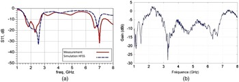
The dimensions of the monopole and the ground plane, the height of the gap and the position of the short-circuited point affect the antenna performances [Reference Liang, Chiau, Chen and Parini12]. A measured gain of 2.7 dBi and a bandwidth of 1.07 GHz from 1.9 to 2.68 GHz are achieved for an optimal configuration. The advantage of such a broadband monopole is to simplify the impedance matching between the antenna and the narrow-bandwidth rectifying circuit. The frequency response of the antenna presented in Fig. 5 acts as a filter for the rectenna. The harmonics will be locked inside the rectifier, leading to a higher efficiency.
Antenna frequency response (a) and gain (b).

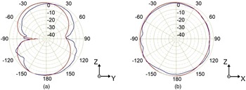
Furthermore, as presented in Fig. 6, radiation patterns in HFSS simulations (red lines) fit the measured results in an anechoic chamber (blue lines). Radiation patterns on the H-plane are not symmetrical owing to the special design of the shorting pin. In practice for sensor application, as the position of the sensor is undefined, the most omnidirectional pattern is needed.
Radiation pattern in E-plane (a) and H-plane (b).

IV. RECTENNA MEASUREMENT
The rectenna was measured with a transmitter–receiver configuration in an anechoic chamber. The rectenna is located 5.586 m far from an emitting horn of 5 dBi gain. A power amplifier of 35 dB gain is connected between the VNA output and the horn since each port of the VNA is limited to 20 dBm RF power. Using the Friis transmission equation [Reference Epp, Khan, Smith and Smith13], the power density at the rectenna position is determined. The output DC voltage across the load resistor has been measured by a voltmeter versus the power density. The efficiency is defined relative to the power at the input of the rectifier. For this we use an effective antenna area of around 22 cm2 deduced form the antenna gain. In the case when the antenna in not integrated with the rectifier (reference case), the input power has been measured by adding a coupler and a power meter. The measured value confirms the preceding calculation.
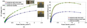
The measured results are shown in Fig. 7. The rectenna with short stub L7 produces DC output of 208.4 mV at the power density of 2.1 µW/cm2. The reference case (antenna + rectifier) leads to 210.6 mV output voltage. These two configurations give close results. So the integration works well and the surface is 30% reduced. At this maximum output voltage level the efficiency is 31%. The maximum efficiency is 34% obtained for 1.3 µW/cm2 power density.
Rectenna output voltage and efficiency versus power density.

A third case is presented, for which the DC loop done by short stub L7 was removed in order to increase the integration. The DC loop is realized by the antenna short circuit. But this action modified the filtering function. It achieved an output DC voltage of 136.8 mV and an equivalent efficiency about 20.6% at the power density 2.1 µW/cm2. This solution is not convenient, but it shows the importance of the filtering.
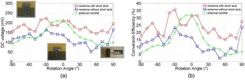
In practical cases, the relative position between ambient sources and sensors is not known and any direction may be concerned. Figure 8 presents measured DC voltages and efficiency of these rectennas against the rotation angle. On the main direction, the rectenna with short stub shows an agreement with the non-planar structure. However, on the other direction, the results of these two rectennas do not fit owing to the radiating effect of planar rectifying circuits. The rectenna with non-planar configuration (reference case) yields a maximum DC output on the main direction. The rectenna with short stub produces better DC output at −30° but worse DC at 60°. So it is more coherent to define an average value to express the performance of the rectenna. The average level of DC voltage 179 mV and equivalent efficiency 23% at the power density 2 µW/cm2 may be considered as the performance the integrated rectenna.
Rectenna output voltage and efficiency versus angle at 2 µW/cm2.

V. CONCLUSION
We presented an integrated monopole rectenna including a rectifier configuration of single serial Schottky diode. The rectifying circuit was optimized for an incident power of −20 dBm at 2.45 GHz. The rectenna was compared with a reference case made by a rectifier and an external antenna. We showed that the filtering function of the antenna increased the efficiency of wireless energy harvesting from 13.6 to 34%. The antenna integration reduced 30% the occupied surface with the same performance. For a single tone signal, this rectenna has an efficiency of 34% at 1.3 µW/cm2 power density. Due to the practical case and the dependency of the efficiency and the output voltage to the space position, we have introduced an average value to qualify the rectenna. The average level of DC voltage is 179 mV and the equivalent efficiency 23% at the power density 2 µW/cm2.
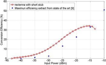
Figure 9 compares our rectenna efficiency to the maximum efficiency obtained by previous research works tested with a single tone signal [Reference Hemour, Zhao and Lorenz10]. Due to the filtering, the diode responsivity and the efficiency optimization, in the low-power range −30 to −20 dBm, our rectenna has a significantly higher efficiency. If we refer to [Reference Takhedmit3], taking into account only the mobile phone ambient level power, this rectenna will have an efficiency of 34% in 1% of practical case and an efficiency of 2% in 50% of practical case. As specified in [Reference Pinuela, Mitcheson and Lucyszyn7], with a modulated and wide band signal, the efficiency can reach 40% in an urban configuration. So to perform energy harvesting in the most practical cases, the rectenna must be integrated in a multiband device and tested with modulated signals. High-efficiency rectenna is an important part of the wireless ambient energy harvesting. Naturally, to use the harvesting energy, the rectenna output voltage should be scaled by a low-power DC/DC converter.
Comparison between single tone efficiency from [Reference Hemour, Zhao and Lorenz10] and rectenna efficiency.

 Yuwei Zhou was born in Jiangxia District, Wuhan, China, in 1986. She received her Master degree from Ecole Polytechnique of the University of Nantes, in 2010. She received her Ph.D. from the same university in 2013. She is now working as an Assistant Professor in the University of Hankou in Jiangxia District, Wuhan, China. Her research interests are mainly focused on the antennas and high-frequency circuits.
 Bruno Froppier was born in France in 1973. He received his Master degree from the University of Nantes in 1999. He received his Ph.D. from the University of Nantes in 2004. He was working as a Research Engineer for a company in 2006. Since he is an Associate Professor at the University of Nantes/IUT of La Roche-sur-Yon, his research interests are mainly focused on the antennas, high-frequency circuits, and wireless energy harvesting.
 Tchanguiz Razban was born in Tabriz, Iran, in 1956. He received his Engineering degree from the University of Tehran, Iran, in 1980. He received his Ph.D. and Doctorat d'Etat from Institut National Polytechnique de Grenoble (INPG), France, in 1983 and 1989, respectively. He was then an Associate Professor in the University of Nice until 1993. He is presently a full Professor of Electrical Engineering at Ecole Polytechnique de Nantes. Since 1999, he has been the Dean of Electrical Engineering Department, Deputy Director and finally Director of Ecole Polytechnique until January 2010. He is now the Director of International affairs of Polytech Nantes. He is a researcher at the Institute of Electronics and Telecommunications of Rennes (IETR) since 1993. He is the author or co-author of more than 70 papers in international journals and conference proceedings. His research interests are mainly focused on the antennas and high-frequency circuits.