I. INTRODUCTION
Metal matrix syntactic foams (MMSFs) are a class of cellular metals that usually contain over 30 vol% of hollow spheres and offer superior blast and energy absorption capabilities due to their distinctive compressive deformation behavior. Similar to other cellular metals,Reference Evans, Hutchinson and Ashby1–Reference Chino and Dunand3 the compressive deformation of MMSFs involves strain to an initial peak stress, followed by a stress plateau that is sustained to a large strain until the foam is fully densified. This behavior is ideal for the absorption of energy at a low stress and has led to numerous studies designed at tailoring the properties of MMSFs through matrix alloy selection, hollow particle reinforcement selection (including composition, diameter, wall thickness, and uniformity), and material process optimization.Reference Balch, O'Dwyer, Davis, Cady, Gray and Dunand4–Reference Peroni, Scapin, Avalle, Weise and Lehmhus30
A majority of the studies on MMSFs have focused on elucidating the roles various combinations of matrix and reinforcement have on the mechanical properties. Various alloys of aluminum,Reference Balch, O'Dwyer, Davis, Cady, Gray and Dunand4–Reference Weise, Zanetti-Bueckmann, Yezerska, Schneider and Haesche20,Reference Vendra and Rabiei26,Reference Rabiei and Vendra27 magnesium,Reference Weise, Zanetti-Bueckmann, Yezerska, Schneider and Haesche20–Reference Daoud, Abou El-khair, Abdel-Aziz and Rohatgi23 zinc,Reference Weise, Zanetti-Bueckmann, Yezerska, Schneider and Haesche20,Reference Daoud24 titanium,Reference Zhao, Tao and Xue10,Reference Mondal, Majumder, Jha, Badkul, Das, Patel and Gupta25 and ironReference Zhao, Tao and Xue10,Reference Vendra and Rabiei26–Reference Peroni, Scapin, Avalle, Weise and Lehmhus30 have been reinforced with hollow spheres of mullite,Reference Balch, O'Dwyer, Davis, Cady, Gray and Dunand4,Reference Balch and Dunand5 fly ash,Reference Wu, Dou, Sun, Jiang, Ding and He6–Reference Zhang and Zhao16,Reference Daoud, Abou El-khair, Abdel-Aziz and Rohatgi23–Reference Mondal, Majumder, Jha, Badkul, Das, Patel and Gupta25 glass,Reference Weise, Zanetti-Bueckmann, Yezerska, Schneider and Haesche20,Reference Peroni, Scapin, Avalle, Weise and Lehmhus30 Al2O3,Reference Kiser, He and Zok17,Reference Drury, Rickles, Sanders, Cochran, Loe, Chia and Kim18,Reference Hartmann, Reindel, Singer, Schwartz, Shih, Wadley and Evans21,Reference Castro and Nutt29 steel,Reference Vendra and Rabiei26–Reference Neville and Rabiei28 carbon,Reference DeFouw and Rohatgi22 and SiC.Reference Luong, Strbik, Hammond, Gupta and Cho19 Due to the large number of combinations that have been used, drawing comparisons can be difficult. A useful method of comparing the mechanical properties of syntactic foams regardless of composition is by the reinforcement wall thickness (t) to diameter (D) ratio. It has been shown in a variety of Al- and Mg-based MMSF systems that the peak strength of these MMSFs increases with increasing t/D ratio.Reference Wu, Dou, Sun, Jiang, Ding and He6,Reference Kiser, He and Zok17,Reference Hartmann, Reindel, Singer, Schwartz, Shih, Wadley and Evans21 A closer examination of the properties of A201-O and A201-T6-aluminaReference Kiser, He and Zok17 syntactic foams and that of magnesium alloy–AluminaReference Hartmann, Reindel, Singer, Schwartz, Shih, Wadley and Evans21 syntactic foams reveals that the peak strength of MMSFs may also be improved by increasing the mechanical properties of the matrix either by heat treatment or alloy selection, respectively.
The process by which the MMSF is synthesized is perhaps the most important factor dictating the mechanical properties of the syntactic foam outside of material selection. Liquid metal processing, especially pressure infiltration, is the most common method for synthesis of MMSFs. Due to the high temperatures used in melting and processing metals, and the reactivity of the metal–ceramic systems, the final compositions of the matrix and reinforcement often differ from the initial constituents, thus affecting the expected mechanical properties. For example, Balch et al.Reference Balch, O'Dwyer, Davis, Cady, Gray and Dunand4 synthesized Al-7075 (T6 and O conditions)/mullite (45 vol% crystalline 3Al2O3–2SiO2, 55 vol% amorphous SiO2) hollow microsphere syntactic foams by a pressure infiltration technique and carefully examined the microstructure and chemistry of the alloy. Due to reaction of the matrix with the mullite reinforcement, SiO2 present in the spheres converted to Al2O3, releasing Si into the surrounding metal. As a result, the final composition of the matrix was closer to that of aluminum alloy, A390, leading to a reduction in the strength compared with what might be expected for the unaltered 7075 alloy. Deleterious reaction may be avoided by using reinforcement coatings or by selecting alloys such that the reinforcement is stable during processing. In a similar study by Orbulov and Ginsztler,Reference Orbulov and Ginsztler12 Al, Al–Si, Al–Mg–Si–Cu, and Al–Cu alloy-E-sphere (36–40 wt% Al2O3, 55–60 wt% SiO2, 1.4–1.6 wt% TiO2, and 0.4–0.5 wt% Fe2O3) syntactic foams were synthesized. X-ray diffraction studies of the various syntactic foams revealed that in all cases except for the foams having a high starting concentration of Si (Al–12Si), the E-spheres partially converted to α-Al2O3 or γ-Al2O3. This displacement reaction of aluminum with the E-spheres resulted in a significant increase in the Si content in these alloys. It followed that heat treatment of the resulting foams was not optimal and resulted in only a moderate increase in strength.Reference Orbulov and Dobránszky11,Reference Orbulov and Ginsztler12
Magnesium alloys have gained significant interest due to their lightweight and attractive properties; however, little work has been published on the synthesis and properties of Mg-based alloy–ceramic hollow sphere syntactic foams. This is likely due to the high reactivity of magnesium with typical reinforcements used in MMSFs. Weise et al.Reference Weise, Zanetti-Bueckmann, Yezerska, Schneider and Haesche20 used a cold chamber high pressure die casting technique to infiltrate Al, Mg, and Zn alloys into preforms of 3M S60HS hollow glass bubbles (soda lime–borosilicate glass). Although Al-glass and Zn-glass syntactic foams were successfully made using this technique, the Mg alloy reacted vigorously with the glass spheres causing them to fracture. Due to the high pressures used, the fractured spheres were completely infiltrated, eliminating the benefits expected from the syntactic foam. DaoudReference Daoud, Abou El-khair, Abdel-Aziz and Rohatgi23 synthesized Mg-ZC63-25 vol% fly ash (61 wt% SiO2, 25 wt% Al2O3, 5 wt% Fe2O3, 1.6 wt% MgO, and 1 wt% TiO2) composites via a stir casting method. The fly ash spheres were shown to have reacted with the magnesium alloy matrix to form a layer of MgO on the surface of the spheres; however, due to the absence of pressure, the spheres remained largely uninfiltrated by Mg-ZC63. In a study by Hartmann,Reference Hartmann, Reindel, Singer, Schwartz, Shih, Wadley and Evans21 magnesium-based alloy–Al2O3 hollow sphere syntactic foams were successfully made by a subatmospheric pressure infiltration technique. In their work, a pressure of 0.5 bar was used to infiltrate cp-Mg, Mg-AM20, Mg-AM50, and Mg-AZ91 into a preform of hollow sintered alumina spheres with varied t/D ratios. Though not within the scope of Hartmann’s work, it is likely that the Al2O3 spheres reacted with Mg to form MgO, thus altering the melt chemistry and mechanical properties.
Although much work has been published on the topic of MMSFs, it is clear that further study of the nature of the effect of matrix/reinforcement composition and temper on their mechanical properties is needed. This study provides an evaluation of the quasistatic and high strain rate properties of AZ91–SiC sphere syntactic foams in the as-cast condition and the quasistatic properties of A206–SiC sphere syntactic foams in the as-cast, T4, and T7 conditions.
II. MATERIALS AND METHODS
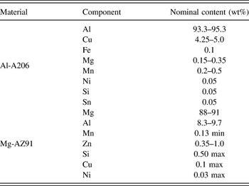
Syntactic foams composed of aluminum alloy Al-A206 and magnesium alloy Mg-AZ91 reinforced with approximately 50 vol% hollow SiC spheres (1 mm nominal diameter, 70 µm wall thickness, and 0.7 g/cm3 bulk density from Deep Springs Technology, Toledo, OH) were synthesized via a subatmospheric pressure infiltration technique. The nominal compositions of the alloys are presented in Table I.
Nominal composition of matrix and reinforcements.

The infiltration method used to synthesize the MMSFs for this study is described in detail elsewhereReference Mortensen and Jin31 and is summarized below. A 12.7 × 12.7 mm2 square cross-section steel tube with one end welded shut was tap-packed with hollow spheres to a height of 35–50 mm. A 2-mm-thick layer of zirconia felt was placed on top of the tap-packed spheres, and finally an ingot of either Al-A206 or Mg-AZ91 alloys was placed inside the tube on top of the zirconia felt to complete the assembly. The zirconia felt is used as a reaction barrier between the aluminum or magnesium alloy melt and the spheres prior to infiltration and served as a filter to remove the oxide layer from the liquid melt. The assembly was then heated in a quartz chamber under vacuum to 750 °C in the case of Al-A206 and 650 °C for Mg-AZ91 and held for 60 min at which time the alloy had fully melted and created a uniform seal on the inner perimeter of the steel tube. Argon gas was then rapidly introduced into the heated quartz chamber until a subatmospheric pressure of 0.5 bar was reached, thereby forcing the molten alloy into the evacuated spaces between the hollow spheres. The quartz chamber containing the sample was kept in the tube furnace at a subatmospheric pressure of 0.5 bar for 10 min. The sample was then removed and quenched in room temperature water. Specimens of the unreinforced alloys were cast using the same procedure described above for comparison with the syntactic foams. Following casting, the specimens were demolded to give final dimensions of 10.4 × 10.4 × 35–50 mm3. Portions of the Al-A206 alloy specimens were heat treated to T4 and T7 conditions, respectively. Those samples that were heat treated were first solutionized at 490–500 °C for 2 h followed by 525–530 °C for 14–20 h. Then they were aged at 21 °C for 120 h for the T4 condition and 4 h at 200 °C for the T7 condition.Reference Chandler32 The Mg-AZ91 alloy specimens were tested in the as-cast condition.
Optical microstructures were obtained using a Nikon Eclipse TS100 microscope (Brighton, MI). A Topcon SM300 (Hasunuma-cho, Itabashi-Ku, Tokyo, Japan) scanning electron microscope (SEM) equipped with energy dispersive spectroscopy (EDS) was used to identify the composition of phases. The density of the composites was measured using a Mettler Toledo AT261 Delta Range Microbalance (Columbus, OH) equipped with a density measurement apparatus (Archimedes method). The specimens were first lightly coated with vacuum grease to prevent infiltration of surface pores during the density measurement.
Quasistatic compression testing was performed in accordance with ASTM C365-11 on specimens sectioned into cubes having each side of 10.4 mm. Testing was carried out using a SATEC Model 50Ud Universal Testing Machine (Norwood, MA) at constant crosshead speed with an initial strain rate of 10−3/s and a self-leveling platen. Strains were calculated from the crosshead displacement and were corrected for deflection of the load frame. The quasistatic compression curves typically exhibited an initial peak followed by a lower plateau stress and later densification. Compression was stopped when the densification stress slightly exceeded the magnitude of the initial peak stress. The toughness of the MMSFs was determined by calculating the area under the quasistatic compressive stress strain curve up to the densification strain and has units corresponding to the energy per unit volume of the material (J/cm3). A variety of methods have been used to report the plateau strength.Reference Zhang, Lee, Singh, Wu and Lindley7,Reference Luong, Strbik, Hammond, Gupta and Cho19,Reference Vendra and Rabiei26,Reference Rabiei and Vendra27 The plateau strength reported in this work is the average of all the measured stress data points between the strain corresponding to the initial peak stress and the densification strain (the strain following the initial peak strength at which the stress reaches the magnitude of the initial peak stress).Reference Luong, Strbik, Hammond, Gupta and Cho19
The high strain rate compressive properties of MMSFs are of technological interest due to their high energy absorption properties and possible application to blast mitigating structures. Aluminum alloys and aluminum alloy composites do not typically exhibit strain rate dependenceReference San Marchi, Cao, Kouzeli and Mortensen33; however, magnesium alloys are known in some cases to show a higher peak strength under high strain rate conditions.Reference Ishikawa, Watanabe and Mukai34,Reference Mukai, Kanahashi, Yamada, Shimojima, Mabuchi, Nieh and Higashi35 Therefore, the Mg-AZ91/SiC syntactic foams synthesized in this work were tested under high strain rate conditions using a Split-Hopkinson pressure bar test apparatus. Details of the test apparatus and methods are discussed at length elsewhereReference Gupta, Luong and Rohatgi36 and are summarized as follows. The cube compression specimens described previously were nested between Inconel incident and transmitter bars having Young’s modulus, density, and sound wave velocity of 195 GPa, 8190 kg/m3, and 4802 m/s, respectively. Once a test is performed by launching a striker bar into the incident bar, which crushes the specimen, data from strain gages mounted at the centers of the incident and transmitter bars are obtained and used to calculate the stress, strain, and strain rate. In this work, strain rates between 537 and 726/s were achieved.
III. RESULTS AND DISCUSSION
A. Microstructure
The properties of MMSFs have been shown to depend greatly on both the t/D (wall thickness/diameter) ratio of the spheres and the properties of the matrix. Features of the matrix that will have an effect on the foam’s properties include:
(i) the presence of defects such as unintended porosity or inclusions,
(ii) the final matrix composition (especially in cases where the matrix reacts with the reinforcement),
(iii) fineness of the microstructure,
(iv) the distribution of phases that form as a result of the solidification sequence in the case of as-cast composites or as a result of the heat treatments.
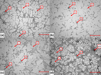
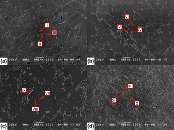
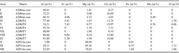
Figures 1 and 2 show the microstructures of the Al-A206 matrix alloy and AZ91D matrix alloy cast and heat treated under the same conditions as the syntactic foams. The as-cast microstructure of A206 [Figs. 1(a) and 2(a)] consists of a dendritic structure of α-phase, whose interdendritic regions are generally made up of Al, Al2Cu, Al2Mn3Cu2, and Al7FeCu2 phases as a result of the eutectic reaction.Reference Talamantes-Silva, Rodríguez, Talamantes-Silva, Valtierra and Colás37,Reference Bäckerud, Chai and Tamminen38 The composition of these phases was determined by EDS, and the results are presented in Table II. As shown in Figs. 1(b) and 1(c) and Figs. 2(b) and 2(c), the interdendritic phases present in the as-cast alloy were only partially dissolved by the solutionizing heat treatment used, which may be due to dissolution of Fe from the mold during processing. The microstructure of the Mg-AZ91 magnesium alloy cast under the same conditions as the corresponding syntactic foam is shown in Figs. 1(d) and 2(d). Under these casting conditions, the microstructure is clearly dendritic and is composed of α-Mg dendrites surrounded by both course and lamellar intermetallics (typically Mg17Al12, the measured compositions are shown in Table II).Reference Srinivasa, Swaminathan, Gunjan, Pillai and Pai39,Reference Braszczyńska-Malik and Zyska40 Interdendritic porosity was also observed.
Microstructures of Al-A206 without reinforcement in (a) as cast, (b) T4, (c) T7 conditions and Mg-AZ91 in the (d) as-cast condition. Unique phases and microstructural features visible in these micrographs are labeled as follows: [in parts (a)–(c)] (i) α-Al, (ii) bright intermetallic (typical of A206), (iii) dark intermetallic (likely present due to Fe dissolution), (iv) porosity; {in part d} (v) α-Mg, (vi) coarse intermetallic, (vii) lamellar intermetallic, and (viii) porosity.

SEM micrographs of Al-A206 without reinforcement in (a) as cast, (b) T4, (c) T7 conditions and Mg-AZ91 in the (d) as-cast condition. EDS was used to identify composition of the labeled phases (I–XII), and the results are tabulated in Table II.

Compositions of the various phases formed in Al-A206 and Mg-AZ91 base alloys (processed under the same conditions as the syntactic foams produced in this study) evaluated by SEM/EDS. Roman numerals in the first column refer to the annotations shown in Fig. 3.

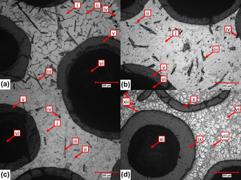
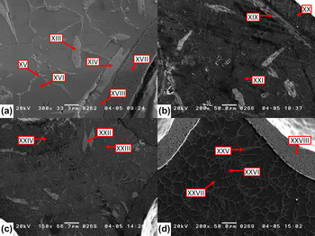
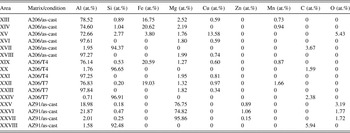
Representative micrographs of the Al-A206 and Mg-AZ91 syntactic foams are shown in Figs. 3(a)–3(c) and 4(a)–4(c) and Figs. 3(d) and 4(d), respectively. Table III presents the results of EDS analysis of the various phases labeled in Fig. 4. The hollow spheres appear to be uniformly distributed and fully encapsulated by the metal matrix with little to no visible porosity in the matrix between the hollow spheres. The Al-A206 as-cast samples show a network of intermetallics throughout the matrix similar to that found in the base alloy without reinforcement. Following the T4 and T7 heat treatments, the intermetallic network present in the as-cast specimens was partially dissolved and precipitated during the aging treatments. Coarse phases containing Fe and Si were also observed to be dispersed in the aluminum alloy specimens. The formation of these intermetallics may be as a result of the presence of excess Si in the matrix due to the partial reaction of the SiC spheres to form aluminum carbides,Reference Ureña, Gómez de Salazar, Gil, Escalera and Baldonedo41 as well as partial dissolution of the steel tube that was used as a crucible. Some cracking of the spheres is also observed in these micrographs, which likely occurred during or after solidification due to coefficient of thermal expansion (CTE) mismatch as there is little to no infiltration of the spheres. The microstructure of the Mg-AZ91/SiC syntactic foam shows refinement in comparison to the matrix alloy cast under similar conditions, which is likely due to the restricted solidification of the liquid in spaces between spheres. EDS of the Mg-AZ91/SiC syntactic foams showed the presence of intermetallics containing small amounts of Si that may be present due to the reaction of the SiC hollow spheres with the alloy matrix.Reference Luo42 The presence of silicon in the alloy may result in the formation of a coarse “Chinese script” Mg2Si intermetallic phase that is detrimental to the mechanical properties of Mg alloysReference Srinivasa, Swaminathan, Gunjan, Pillai and Pai39; however, this intermetallic phase was not observed in the syntactic foams synthesized in this study.
Representative microstructures of the Al-A206/SiC (a–c) and Mg-AZ91/SiC (d) syntactic foams synthesized in this study. The micrographs for the Al-A206/SiC foams are shown in the (a) as-cast, (b) T4, and (c) T7 conditions, respectively. Unique phases and microstructural features visible in these micrographs are labeled as follows: [in parts (a)–(c)] (i) α-Al, (ii) bright intermetallic (typical of A206), (iii) dark intermetallic (likely present due to Fe dissolution), (iv) porosity, (v) SiC hollow sphere wall, (vi) hollow pore within SiC sphere; {in part d} (vii) α-Mg, (viii) intermetallic, (ix) SiC hollow sphere wall, (x) cracked and filled SiC sphere, (xi) hollow pore within SiC sphere, and (xii) porosity.

SEM micrographs of the Al-A206/SiC (a–c) and Mg-AZ91/SiC (d) syntactic foams synthesized in this study. The micrographs for the Al-A206/SiC foams are shown in the (a) as-cast, (b) T4, and (c) T7 conditions, respectively. EDS was used to identify composition of the labeled phases (XIII–XXVIII), and the results are tabulated in Table III.

Compositions of the various phases formed in Al-A206/SiC and Mg-AZ91/SiC syntactic foams evaluated by SEM/EDS. Roman numerals in the first column refer to the annotations shown in Fig. 4.

B. Quasistatic compression properties
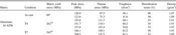
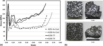
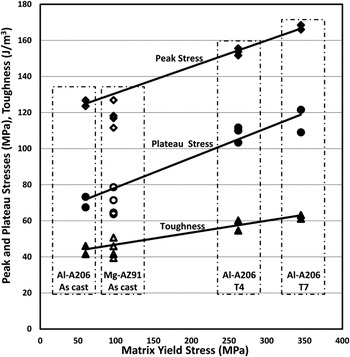
Table IV reports the values of peak strength, plateau strength, densification strain, and energy absorption for the syntactic foams synthesized in this study. Representative quasistatic engineering stress–strain curves are shown in Fig. 5(a), and the macroscopic appearance of the fractured specimens tested in quasistatic compression is shown in Fig. 5(b). The fracture of the hollow SiC spheres and shearing of the matrix during deformation caused sections of the sample to break and fall away from the bulk as shown in Fig. 5(b). From this data, Fig. 6 suggests that the peak stress in this work is influenced by yield strength, as peak stress increases from as-cast to T4 to T7, which is similar to the trend in yield stress in the case of the unreinforced alloy.
Summary of quasistatic compression data for Al-A206/SiC and Mg-AZ91/SiC syntactic foams.

a Estimated.
(a) Typical compressive stress–strain curves for Al-A206/SiC and Mg-AZ91/SiC syntactic foams. (b) Fractured specimens tested in compression under quasistatic strain rates shown in the pretest (left side) and posttest (right side) conditions. The top two specimens are Al-A206/SiC syntactic foams and the bottom two are Mg-AZ91/SiC syntactic foams.

Average peak strength, plateau strength, and toughness versus yield strength of the base alloy.

C. High strain rate compression properties
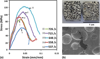
Figure 7(a) shows the stress–strain curves for the Mg-AZ91/SiC under the various strain rates tested. It should be noted that in Split-Hopkinson pressure bar testing, only the time equal to the stress pulse width is available for deforming the specimen, and thus if the specimen does not reach its densification strain within this time frame, the test remains incomplete.Reference Gupta, Luong and Rohatgi36 As the results in Fig. 7(a) indicate that a maximum strain of only approximately 10% was obtained, only the peak strength is examined in detail in this work. Large variation is observed in the measured peak strength under high strain rates; however, despite this large variation, the peak strength remains essentially constant when compared in the strain rate range from 10−3 to 726/s. An example of the fractured specimens tested at strain rates of 547 and 648/s is shown in Fig. 7(b) along with a SEM image of a crack bisecting a SiC sphere. Little difference was observed in the macroscopic appearance of specimens tested at higher strain rates, however increased crushing of spheres was observed.
(a) High strain rate compression response of Mg-AZ91/SiC syntactic foams; (b) fractured specimens compressed at high strain rates. The top images show fractured specimens tested at strain rates of (from left to right) 537 and 648/s, respectively. Load was applied on the face that is visible in the image, causing compression through the thickness of the specimen imaged. The lower image shows a typical fracture event in the 537/s specimen, where a crack is shown to shear a SiC hollow sphere (taken with Hitachi S-3400 N SEM). Higher strain rates led to increased crushing of the spheres.

A strain rate sensitivity parameter Σ has been used by othersReference San Marchi, Cao, Kouzeli and Mortensen33 to identify strengthening phenomena in the case of high strain rate deformation as defined by the following equation:
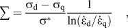 $$\sum = {{{{\rm{\sigma }}_{\rm{d}}} - {{\rm{\sigma }}_{\rm{q}}}} \over {{{\rm{\sigma }}^{{*}}}}}{1 \over {\ln ({{{{\dot \varepsilon }}}_{\rm{d}}}/{{{{\dot \varepsilon }}}_{\rm{q}}})}}\quad ,$$
where σ is the stress at a given strain, σ* is the stress at a given strain at a reference strain rate of 10−3/s,  ${{\dot \varepsilon }}$ is the strain rate, and the subscripts d and q refer to dynamic and quasistatic testing, respectively.
The peak stress was used for the dynamic, quasistatic, and reference stresses after the analysis of Balch et al.Reference Balch, O'Dwyer, Davis, Cady, Gray and Dunand4 due to the unique deformation behavior of metal foams in comparison to alloys or composites. The calculated sensitivity parameter for these composites was approximately 0.01 or less, which is expected for cellular AZ91Reference Mukai, Kanahashi, Yamada, Shimojima, Mabuchi, Nieh and Higashi35 at similar strain rates, leading to the conclusion that the strain rate sensitivity in the case of the Mg-AZ91–SiC syntactic foams is primarily dependent on the matrix properties and not greatly affected by the presence of the SiC hollow spheres within the range of strain rates investigated in this study.
IV. CONCLUSIONS
The microstructure and quasistatic properties of Al-A206/SiC and Mg-AZ91/SiC hollow sphere syntactic foams have been studied to determine the effect of matrix strength. The peak strength, plateau strength, and toughness of the foams increase with increasing yield stress of the matrix material. The Al-A206/SiC and Mg-AZ91/SiC syntactic foams synthesized in this study exhibited a higher specific plateau strength and specific energy absorption than many of the syntactic foams reported in the literature, leading to insights regarding how the properties of MMSFs may be optimized. The high strain rate properties of the Mg-AZ91/SiC foams were studied, and no strain rate sensitivity was observed in the strain rate range of 0.001–726/s.
ACKNOWLEDGMENTS
This research was supported by the U.S. Army-TARDEC through Tank and Automotive Command R&D Contract No. W56HZV-08-C-0716. The authors would like to acknowledge Oliver M. Strbik III of Deep Springs Technology, LLC for supply of the SiC hollow spheres used in this study. N. Gupta acknowledges Office of Naval Research grant N00014-10-1-0988 with Dr. Yapa D.S. Rajapakse as the program manager. Disclaimer: Reference herein to any specific commercial company, product, process, or service by trade name, trademark, manufacturer, or otherwise, does not necessarily constitute or imply its endorsement, recommendation, or favoring by the United States Government or the Department of the Army (DoA). The opinions of the authors expressed herein do not necessarily state or reflect those of the United States Government or the DoA and shall not be used for advertising or product endorsement purposes.