1. INTRODUCTION
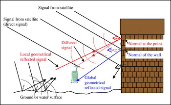
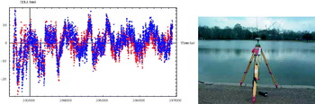
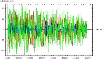
The multipath effect is one of the most important GNSS error sources in high precision positioning. Multipath errors are caused when direct signals from satellites are mixed with those reflected from objects in the vicinity of the antenna as shown in Figure 1. Phase multipath errors at static antennas show sinusoidal patterns and sidereal day-to-day repeatability as shown in Figure 2, however, phase multipath errors in kinematic antennas behave like random noise as shown in Figure 3, especially for highly dynamic applications. Therefore, different multipath mitigation techniques can be applied to different applications, which have different multipath characteristics. This paper describes the theories and test results of some state-of-the-art and our novel software based phase multipath mitigation techniques. They include phase multipath estimation using SNR data, phase multipath estimation through the use of closely spaced antennas, multipath mitigation stochastic models such as the satellite elevation angle model and SNR-based models (SIGMA-ε model and our modified SNR-based model), and our own novel ray-tracing method. The effectiveness and limitations of the techniques for a variety of scenarios such as static and kinematic antennas, and long-delay or short-delay multipath are also discussed.
Multipath from any surface in the vicinity of the antenna.

(Left) Day-to-day repeatability of double difference residuals (mainly consist of phase multipath errors) in L1 data for PRN11 in Day 1 (red) and Day 2 (blue) of the multipath contaminated data (reflection from the water surface of the Serpentine) collection in Hyde Park of London (right).

Simulated GPS three-frequency (red: L1, blue: L2, green: L5) phase multipath error in a trajectory in an environment with about fifty reflectors made of concrete (Lau, Reference Lau2005).

The theoretical backgrounds of the multipath mitigation techniques considered in the paper are given in Section 2. Test dataset descriptions are presented in Section 3 and test results of the techniques are given in Section 4. Analysis of results, along with the effectiveness and limitations of the techniques are described in detail in Section 5. Finally, recommendations are made on the use of different phase multipath mitigation techniques for a variety of scenarios such as static and kinematic antennas, and long-delay or short-delay multipath. Concluding remarks on the techniques and investigations are also included.
2. SOFTWARE-BASED MULTIPATH MITIGATION TECHNIQUES
2.1. SNR-based phase multipath estimation technique
This technique is based on the relationship of phase multipath error and the multipath contaminated SNR described in (Comp and Axelrad, Reference Comp and Axelrad1996) and (Lau and Cross, Reference Lau and Cross2005) to estimate the amplitude and phase of the multipath contaminated SNR and then compute the phase multipath error.
The nominal SNR and gain efficiency are used to find the multipath contaminated part of the raw SNR by:

where SNR MP denotes the multipath contaminated part of the raw SNR (SNR raw), G ant denotes the satellite elevation angle dependent antenna gain, SNR 0 denotes the nominal SNR, and G eff denotes the gain efficiency that is a function of the satellite elevation angle θelv; SNR 0 and Geff(θelv) are determined by calibrations using “multipath-free” data. The performance of this SNR-based multipath error estimation technique therefore relies heavily on the calibrated parameters in Equation (1). Comp and Axelrad (Reference Comp and Axelrad1996) proposed using the determined multipath frequency by Adaptive Notch Filter (ANF) and the multipath contaminated SNR data to find the revised nominal SNR by Adaptive Least Squares (ALS). However, investigations carried out by the authors of this paper have led to the conclusion that the revised nominal SNR determined by this method may be too noisy in real-time applications.
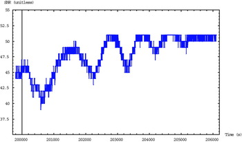
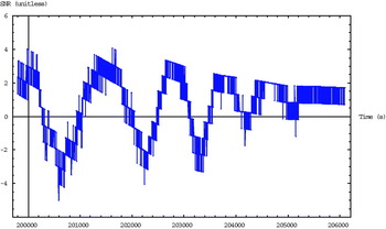
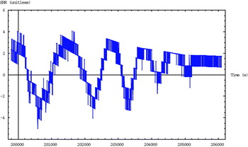
ANF is widely used in signal processing because most undesired noise or interference in telecommunications systems is sinusoidal in nature (Regalia, Reference Regalia1994), (Ghose, Reference Ghose1996). In this investigation, the Adaptive Lattice Notch Filter (ALNF) described in (Regalia, Reference Regalia1994) is used to estimate the frequency of the phase multipath errors in static and low dynamic applications. The input to the ALNF is the multipath contaminated SNR, which is obtained by Equation (1). An example of the raw SNRs for the satellite PRN01 in the LCPC dataset is shown in Figure 4 and the extracted multipath contaminated SNRs obtained by Equation (1) are shown in Figure 5, note the sinusoidal phase multipath pattern from about GPS seconds 200 000 to 204 000. The angular frequency of the multipath error is the output from ALNF and the estimated multipath frequency is then used to estimate the argument and amplitude of the multipath error in an Adaptive Comb Filter (ACF), which is described in (Händel and Tichavský, Reference Händel and Tichavský1994) and it is similar to the ALS described in (Comp and Axelrad, Reference Comp and Axelrad1996) and (Bétaille, Reference Bétaille2004). The multipath error is reproduced using the estimated argument and amplitude as follows:

where ΦMP denotes the reproduced phase multipath error, k is the receiver dependent scale factor, which relates the SNR and phase multipath error, n denotes the counter of multipath errors (or reflectors which cause multipath) in the phase measurement, r denotes the total number of multipath errors (or reflectors which cause multipath) in the phase measurement, A denotes the estimated amplitude of the multipath error, and θ denotes the argument or phase of the multipath error. A π/2 shift is required to align the phase of the SNR-based estimated multipath error to the phase of the carrier phase multipath error. This is because the multipath contaminated SNR is always different to the phase multipath error by 90° (π/2), however, the sign of this phase difference is unknown (±90°) in practice and this leads to the estimated phase multipath error sometimes being different to the true multipath error by 180°.
Raw L1 SNR of the satellite PRN01 in the LCPC dataset.
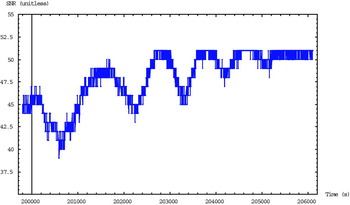
Extracted L1 multipath contaminated SNR of the satellite PRN01 in the LCPC dataset.
2.2. Phase multipath estimation through the use of closely spaced antennas
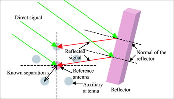
This technique is based on the correlation of phase multipath errors at closely spaced antennas (Ray, Reference Ray2000) as shown in Figure 6. Since the antennas are very close, most GNSS error sources are highly correlated and can be eliminated by differencing. However, phase multipath errors are highly sensitive to the antenna positions and the observing carrier frequencies, the phase multipath errors of a particular carrier frequency at the closely spaced antennas are correlated with the given geometry of the antenna array architecture but their magnitudes are different and hence the errors cannot be eliminated by differencing.
Simple illustration of an antenna array (six antennas) in the presence of multipath errors from a reflector.
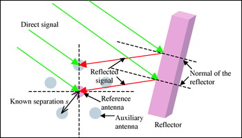
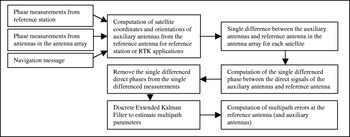
This technique uses the known separation s and the single difference measurements between the reference antenna and the auxiliary antennas (see Figure 6) to estimate the phase multipath parameters at the reference antenna as well as the auxiliary antennas. In this paper, only L1 phase multipath errors at the reference antenna are of interest. The detailed description and complete derivation of the antenna array model can be found in (Lau and Cross, Reference Lau and Cross2006a). The outline of the algorithm is given in Figure 7.
Flowchart for the processing steps of the antenna array algorithm.

The fundamental equation used in the multipath error parameter estimation is:

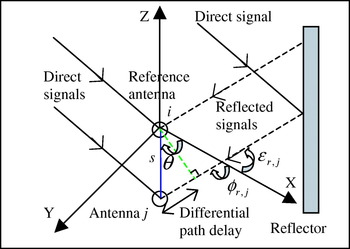
where ψij denotes the single difference phase multipath error (in radians) in the measurements collected at antennas i and j, αi denotes the damping factor of the reflected signal at the reference antenna i, φi denotes the phase of reflected signal (the phase shift of the indirect signal relative to the direct signal) at the reference antenna i in radians, λL1 denotes the GNSS L1 wavelength, ϕr denotes the azimuth of the reflected signal from the reflector r at the antenna array, and εr denotes the elevation angle of the indirect signal from the reflector r at the antenna array (see Figure 8).
Differential path delay between two antennas in an antenna array.

A discrete Extended Kalman Filter (EKF) is used to estimate the multipath parameters, the computation issues/steps of EKF can be found in (Bar-Shalom et al., Reference Bar-Shalom, Li and Kirubarajan2001) and (Brown and Hwang, Reference Brown and Hwang1996). In order to save space in this paper, a single multipath model (one multipath/reflection per measurement) is described in this section. The parameters for a multipath from a reflector and a satellite, as shown in Figure 8, are:

Moreover, the design matrix H for the EKF can be written as:
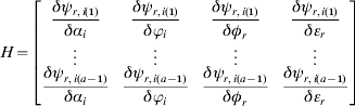
where r denotes the reflector, i denotes the reference antenna, () denotes the auxiliary antenna (index) in the antenna array, a denotes the total number of antennas in the antenna array. Therefore, ψr,i(a) denotes the single differenced phase multipath error (after Phase Lock Loop (PLL)) between phase measurements obtained from a satellite at antennas i and a in the presence of multipath from the reflector r; see also in Equation (3). The partial derivatives of the single differenced multipath error in Equation (3) with respect to the unknowns in Equation (4) are:
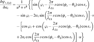

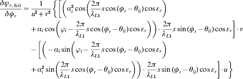
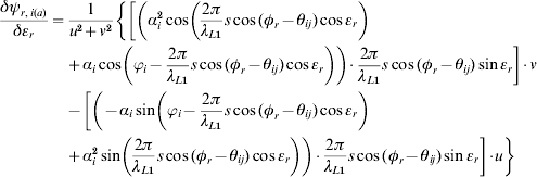
where θij denotes the azimuth at the reference antenna i to the auxiliary antenna j, u is the numerator and v is the denominator in Equation (3).
The four estimated multipath parameters for each satellite and reflector, which are the damping factor, relative phase shift to the direct signal, the azimuth and elevation angle of the multipath signal at the reference antenna of the antenna array, are used to compute the phase multipath errors at the antennas in the antenna array. In fact, only the estimated damping factor and phase shift are required to compute the multipath error at the reference antenna using Equation (10). The less interesting phase multipath errors at the auxiliary antennas can be computed using Equations (11) and (10).
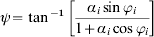

One of the important factors of this algorithm is the determination of the single difference of the direct signals between the auxiliary antennas and the reference antenna in an antenna array. Currently, the single differences of the direct signals of an antenna array in RTK applications can only be computed using the single- or dual-frequency GPS carrier-phase-based estimated positions of at least two antennas in an antenna array (the relative geometry of the antennas in an antenna array is known). The performance of this technique is highly dependent on the accuracy of the estimated positions of any two antennas in the array in RTK applications. However, small errors (mainly due to multipath errors) in the estimated positions of a pair of antennas in the array affect the accuracy of azimuth determination (usually from the reference antenna to an auxiliary antenna), which is essential for the computation of the single difference of the direct signals, seriously because the antennas are closely arranged (usually less than 10 cm). However, it is trivial to compute the single differences of the direct signals when applying this technique for reference stations because the antennas' positions in the antenna array can be determined accurately before applying this technique.
GPS modernisation is being undertaken and the European GNSS, named Galileo, is being developed to provide three open-service carrier frequencies and its Full Operational Capability (FOC) is scheduled for 2010. After GPS modernisation and the development of Galileo, six open-service signals will be available. A possible improvement of RTK positioning accuracy on the determination of the orientation of the antenna array in the satellite reference frame using Galileo+GPS multiple-frequency data is investigated in this paper while the performance of this technique on the current GPS dual-frequency system has been investigated in (Ray, Reference Ray2000).
2.3. Multipath mitigation stochastic models
2.3.1. Simple Elevation Angle Based Stochastic Model (EASM)
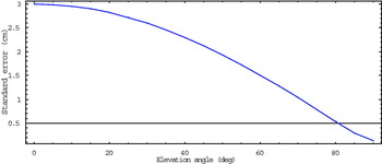
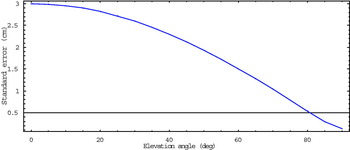
The weighting parameter, which is usually called the standard deviation in stochastic models, used in this model assumes that the relationship of the multipath error and the satellite elevation angle is approximately linear. The simplest parameter is the cosine of the satellite elevation angle (Barnes, et al., Reference Barnes, Ackroyd and Cross1998) and (Collins and Langley, Reference Collins and Langley1999). However, in order to avoid the parameter equaling zero (no statistical error for a measurement) when the elevation angle is at the zenith, the standard deviation σ used in this investigation is determined by:

where ψm denotes the practical maximum phase multipath error; 3 cm is used in this investigation, and E denotes the satellite elevation angle. The elevation angle dependent standard deviations are plotted in Figure 9.
Standard deviations of satellite elevation angles in a simple elevation angle dependent stochastic model.
2.3.2. SIGMA-ε model
The SIGMA-ε method was proposed by (Hartinger and Brunner, Reference Hartinger and Brunner1999). It uses the measured Carrier-to-Noise Ratio (CNR) from receivers to estimate the phase variances ( ) of measurements by the following formula:
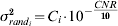
where C i is a factor consisting of the carrier loop noise bandwidth and a conversion term from cycles2 to millimetres2, which includes the L i wavelength. CNR denotes the measured CNR. The SIGMA-ε model uses the variance propagation law to compute the double difference (DD) variance (tailored for GPS surveying) from the phase variances () of the measurements, which are used to form the DD measurements. CNR is effectively equivalent to SNR. Therefore, the following formula can be used to determine the phase variance:

where SNR measured denotes the measured SNR. A two-digit resolution SNR measured, obtained from the observation file in the Extended RINEX format, is used in this investigation.
2.3.3. “Modified” SNR Stochastic Model (MSSM)
The orthogonality of SNR and carrier-phase multipath error causes difficulty in the implementation of a SNR-based stochastic model. This is because the carrier-phase multipath error is a maximum when the measured SNR is close to the nominal SNR for the multipath contaminated measurement. However, the measured SNR is also close to the nominal SNR when the measurement is free of multipath. The detailed description on the relationship between SNR and phase multipath error can be found in (Lau and Cross, Reference Lau and Cross2006b). In RTK applications, multipath errors may be uncorrelated between epochs because of the rapid change of satellite-reflector-antenna geometry. Therefore, the first step of our MSSM algorithm is to determine whether the carrier-phase measurement has multipath or not in a particular single-epoch of data. This is carried out by inspection of dual-frequency pseudorange multipath errors. Since the pseudorange multipath error is frequency dependent (the error depends on the chipping rate and code tracking loop design of different GNSS code modulations (e.g., GPS C/A and P codes)), the pseudorange multipath error of the L1 frequency is usually different to that of the L2 frequency and if we assume that the pseudorange multipath errors are usually at least an order of magnitude greater than those for the phase, they can be determined by (Cross, Reference Cross2002):


where M P1 and M P2 denote the pseudorange multipath errors in L1 and L2, respectively, B 1 and B 2 denote the ambiguities of L1 and L2 carriers, respectively, P 1 and P 2 denote the L1 and L2 pseudoranges, respectively, L 1 and L 2 denote the L1 and L2 carrier-phases, respectively, C 1 and C 2 denote the carrier-phase ambiguities related constants of L1 and L2, respectively, and α denotes f 12/f 22.
The second step is to compute the constants C 1 and C 2. This is performed using the extracted SNR, see Equation (1), based on the relationship of SNR and pseudorange multipath error described in (Lau and Cross, Reference Lau and Cross2006b). The constants are computed each time the signs of the extracted SNRs in L1 and L2 change, which are close to the zero pseudorange multipath errors and the zero extracted SNRs. The computed constants are used in the following epochs so long as there are no cycle slips, or cycle slips have been repaired. Before the constants are resolved or if there are un-repaired cycle slips, the scaled extracted SNR standard deviation is used:

where C denotes the receiver dependent scale factor between SNR MP and carrier-phase multipath error. C=300 is used in the proposed algorithm for the Leica System 530 receivers. This makes 1 dB equivalent to about 3·3 mm, which is identical to the description of the mean 6 dB equivalent to 20 mm for conventional GPS surveying antennas in (Brown, Reference Brown2001).
The next step is to determine the standard deviation of the carrier-phase measurement for the stochastic model. If no multipath is detected from the previous step, the scaled extracted SNR standard error is used. If there has been multipath, the following three steps are used to determine the standard deviation for the carrier-phase measurement:
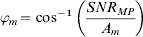
i) Determine the phase shift φm using the relationship of extracted SNR SNR MP, the practical maximum multipath contaminated SNR A m, and the phase shift φm:
(18)
where A m=6 dB is used in the proposed algorithm. This value may be less than the “true” practical maximum multipath contaminated SNR. However, it will increase the phase shift angle of the multipath signal φm and therefore have a higher impact on the proposed stochastic model (i.e. it will discriminate more strongly between satellites with and without multipath).
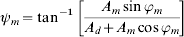
ii) Estimate the carrier-phase multipath error by substituting the determined phase shift φm, the nominal SNR A d and the theoretical maximum multipath amplitude A m in the following equation:
(19)The theoretical maximum multipath amplitude is set to 15 dB in the proposed algorithm. This value is less than the theoretical possible maximum multipath amplitude (it is equal to the nominal amplitude of the direct signal) but greater than the practical maximum multipath contaminated SNR. If the arbitrary theoretical maximum multipath amplitude is too small, the impact of the multipath contaminated measurements on the stochastic model would be too small. On the contrary, if the arbitrary amplitude is too large, the impact of the multipath contaminated measurements on the stochastic model would be too great and lead to the measurements having an insignificant impact on the position solution (and in turn lead to poor geometry).iii) Form the stochastic model using the error propagation law.
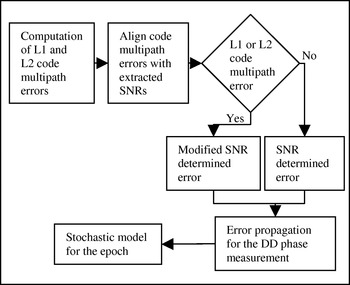
The MSSM algorithm is summarised in Figure 10. Since the practical maximum multipath contaminated SNR and the theoretical maximum multipath amplitude may not truly represent the real amplitudes, this method cannot be used to correct the multipath errors in carrier-phase measurements but it can be used to reflect the presence of multipath error in stochastic model.
Flowchart for the MSSM algorithm.

2.4. Ray-tracing method
Our novel ray-tracing method uses the accurate satellite, reflectors and antenna positions, reflectors' permittivities, receiver's correlation space, and receiving antenna gain pattern to compute the phase multipath errors for all GNSS frequencies. Since the algorithm involves many computational steps and formulas, it is difficult to describe the complete algorithm in the limited space of this paper. The complete algorithm is described in (Lau and Cross, Reference Lau and Cross2007) and summarised as follows:
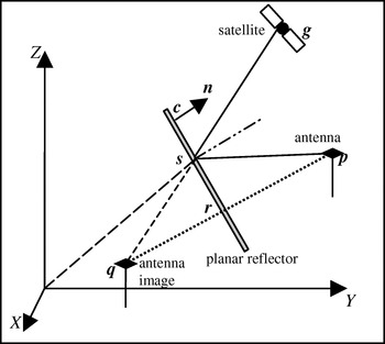
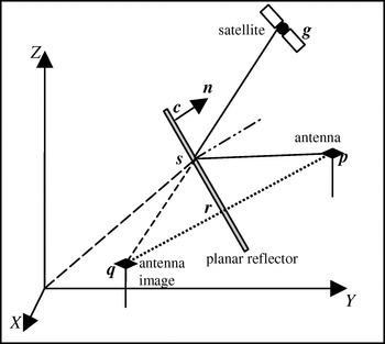
i) Determine whether or not multipath would occur if the reflector was of infinite size to find the reflection point. The geometry of the tracing of a reflected signal is shown in Figure 11. Geometrical formulas are used to find the intersection points r and s on the reflector.
Figure 11.Geometry of the tracing of a reflected ray.
ii) Decide if the reflection point is within the boundary of the reflector as described by the coordinates of its four corners (an irregular surface can be differentiated into small rectangles) – only then will the reflector cause multipath.
iii) Compute the damping factor α of the reflected signal using the computed Fresnel reflection coefficient ρ, polarization efficiency F, and antenna gain ratio ηa:
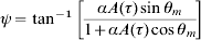
(20)This step is very important for determination of the correct relative amplitude of the reflected signal. The detailed algorithm for the determination of these important parameters ρ, F, and ηa can be found in (Lau and Cross, Reference Lau and Cross2007).iv) Compute the phase multipath error ψ, having computed the multipath phase shift and correlation function:
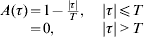
(21)where A denotes the PRN code correlation function, τ is the time-delay of the reflected signal relative to the direct signal, and A(τ) is(22)where T is the PRN code bit period, or correlator spacing, and θm in Equation (21) denotes the phase shift due to the extra distance travelled by the multipath signal relative to the Line-Of-Sight (LOS) signal.v) Apply the phase centre variations using the incidence angles of the LOS and reflected signals and the input phase centre variation table.

3. Test Data Description
This section describes the real datasets used to test the SNR-based phase multipath estimation technique described in Section 2.1, the multipath mitigation stochastic models described in Section 2.3 and the ray-tracing method described in Section 2.4, and the design and simulation of GPS and Galileo multiple-frequency data for testing of the antenna array technique described in Section 2.2.
3.1. Description of the real test datasets
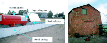
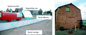
Two datasets have been collected in well-controlled experimental sites, one in Laboratoire Central des Ponts et Chaussées (LCPC) near Nantes in France, and the other on the campus of the University of Nottingham in UK as part of the SPACE project. Two Leica Geosystems SR530 receivers and AT502 light-weight antennas were used in the LCPC data collection. In order to create a sufficiently large multipath signal, a 5 m by 2·5 m steel panel was constructed and placed near (about 1 m) to one of the receiving antennas (see Figure 12 Left). Two Leica Geosystems SR530 receivers and AT504 choke-ring antennas were used in the Nottingham data collection, one of the antennas was setup about 1·9 m away from a 5 m by 4·5 m (approx) brick wall for reception of multipath signals (see Figure 12 Right). Short reflector-antenna distance multipath data is used to validate the algorithms because short-delay multipath is very hard to filter out in receiver hardware design. On the other hand, the reference receivers for the datasets are within 100 m from the roving receivers. Therefore, the residuals after differencing consist of mainly multipath errors.
(Left). Test data collection site in LCPC (Bétaille, Reference Bétaille2004). (Right). Setup for collection of multipath data in Nottingham.
3.2. Description of the simulated datasets for the test of the antenna array technique
Testing of the antenna array technique with GNSS multiple-frequency data must be carried out by using simulated data because the multiple-frequency data is not available at the time of this research. UCL GNSS data simulator Version 2.0 (GPS L1C incorporated) is used to simulate the testing datasets. Details of the simulator can be found in (Lau, Reference Lau2005). The simulator can generate very realistic phase multipath errors; the rigorous validations of the simulator can be found in (Lau, Reference Lau2005) and (Lau and Cross, Reference Lau and Cross2007).
Testing of the antenna array technique is divided into two cases. Case 1 is the application of the algorithm for a reference station with the known orientation of the closely spaced antennas in the satellite reference frame. Case 2 is for solutions that need to determine the orientation of the “kinematic” closely spaced antennas in the satellite reference frame using the classical least squares single-epoch carrier phase based estimated positions. Case 2 is divided into two further cases, firstly case 2-1 which uses the current reliable GPS L1 only data and case 2-2 which uses modernised GPS+Galileo multiple-frequency data. Modernised GPS and Galileo data “collected” at the closely spaced antennas are also simulated using the UCL GNSS data simulator. Moreover, a RTK reference station for Cases 2-1 and 2-2 is simulated at 500 m to the north of the reference antenna of the antenna array.
This testing doesn't address the following scenarios but they may be investigated later and discussed in another paper:
● The antenna array is tilted while it moves. The antenna array is assumed to be horizontal (attitude determination of the antenna array should be integrated to the algorithm).
● Reflected signals come from below the horizontal plane of the antenna array.
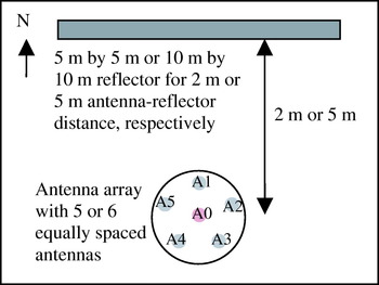
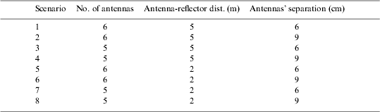
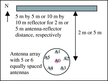
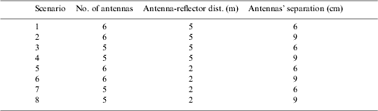
The testing scenarios are designed to have two numbers of antennas in the antenna array, two antenna-reflector distances, and two known antennas' separations. The scenarios for Cases 1, 2-1, and 2-2 are listed in Table 1 and the geometry of the antenna array and reflector in the simulation is illustrated in Figure 13. The observation period in the simulation is 11:00–12:00 (UTC) in 3rd October 2005.
Geometry of the antenna array and reflector in the simulation.
List of testing scenarios.
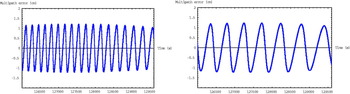
Scenarios of the three cases are processed by the multipath estimation algorithm and their estimated phase multipath errors at the reference antenna are compared with the simulated phase multipath errors. GPS PRN26 has been identified to have multipath in the geometry shown in Figure 13 for the whole observation period in all testing datasets. Therefore, the results shown in Section 4.2 are all referred to GPS PRN26. The “truth” simulated phase multipath errors in GPS PRN26's measurements at the reference antenna for the 5 m and 2 m antenna-reflector distance scenarios are shown in Figure 14.
Simulated phase multipath errors at the reference antenna in the antenna array for the 5 m antenna-reflector distance test dataset (Left) and the 2 m antenna-reflector distance test dataset (Right).
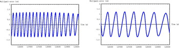
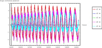
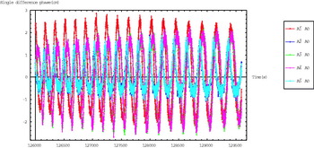
“Global” tuning of the EKF process and measurement noises has been done for all the scenarios, therefore, some results may show loss of track sometimes. Individual tuning would definitely improve the testing results, however, it is difficult to have one set of process and measurement noises for all scenarios of multipath parameters and errors in practice (no prior knowledge of reflectors' positions). This is because the frequency of multipath errors in time series depends on the rate of change of differential path delay, i.e. usually high frequency for distant reflectors and hence high change rate for the phase of multipath error (due to the rapid change of the phase shift of the indirect signal). This can be seen in the simulated phase multipath errors for the 5 m and 2 m antenna-reflector distances in Figure 14. Process noises and measurement noise used in EKF are 10−4 s−1 for the damping factor, 10−2 rad2 s−1 for the phase shift, 10−6 rad2 s−1 for the azimuth, 10−6 rad2 s−1 for the elevation angle, and 10−3 rad2 (10−3 m standard deviation) for the phase measurement. An example of the input measurements to EKF in the Scenario 1 of Case 1 is shown in Figure 15.
Single differenced multipath errors after removal of the SD direct signals act as the measurements for EKF in Scenario 1 of Case 1.
4. Test Results and Analyses
This section describes the test results of the multipath mitigation techniques described in Section 2 using the real and simulated datasets described in Section 3.
4.1. SNR-based phase multipath estimation technique
This algorithm is tested using data from three satellites collected at LCPC and in Nottingham. The datasets are processed by the SNR-based phase multipath error estimation algorithm described in Section 2.1. For each receiver and antenna combination, several processing parameters are required to tune in order to obtain optimum results. These are the ALNF bandwidth and step size, and the receiver dependent constant k in Equation (2).
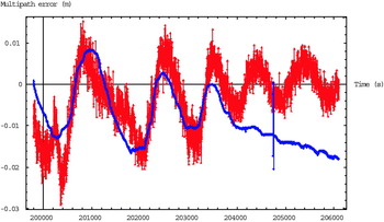
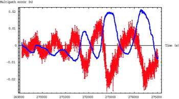
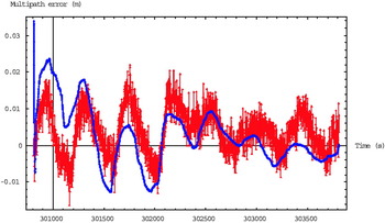
Figure 16 shows the SNR-based estimated phase multipath errors (in blue) for satellite PRN01 in the LCPC dataset compared with the DD residuals (in red), which comprise mainly multipath errors in this short baseline. The results for the satellites PRN02 in the LCPC dataset and PRN01 in the Nottingham dataset are shown in Figures 17 and 18 respectively.
DD residual (mainly multipath error) and the estimated phase multipath error for the satellite PRN01 in the LCPC dataset.

DD residual (mainly multipath error) and estimated phase multipath error for the satellite PRN02 in the LCPC dataset.
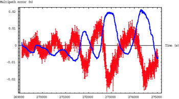
DD residual (mainly multipath error) and estimated phase multipath error for the satellite PRN01 in the Nottingham dataset.

In about the first 4000 seconds of Figure 16, there is a good agreement between the estimated multipath errors and the DD residuals. Also the estimated multipath errors don't show any sign errors in this dataset. After about epoch 20 400 GPS seconds in Figure 16, the estimated phase multipath errors are very different from the DD residuals because the extracted multipath contaminated SNR doesn't show the sinusoidal phase multipath pattern in that period, see the blue line in Figure 5.
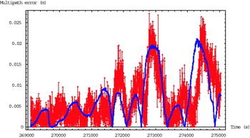
The results from the PRN02 data in the LCPC dataset in Figure 17 show an obvious sign error for the estimated phase multipath error throughout the time series. It seems that the estimated phase multipath errors would fit the DD residuals if the opposite sign was applied in Equation (2), Figure 19 shows this argument if absolute values are taken for the estimated multipath errors and DD residuals.
Absolute DD residual (multipath error) and absolute estimated phase multipath error for the satellite PRN02 in the LCPC dataset (Absolute values for Figure 17).

The results from the PRN01 data collected in Nottingham in Figure 18 do not show any sign errors except the last half cycle of the first cycle from about GPS seconds 301 000 to 301 200. This is probably due to the extracted multipath contaminated SNR not having a zero-mean sinusoidal pattern in the first cycle. Also, the agreement between the DD residuals and the estimated phase multipath errors is not very good.
From Figures 16 to 18, the reduced performance of the algorithm can be seen when the real multipath errors as shown in the DD residuals are about less than 1 cm. This is probably due to the “noise” in the extracted multipath contaminated SNR, which causes tracking problems in the filters, as shown in about the last half observation periods of Figures 16 and 18. In this case, the noise caused by multipath in SNR may be comparable to the other noise (e.g. white noise and satellite signal tracking noise) in SNR.
4.2. Phase multipath estimation through the use of closely spaced antennas
The statistical results (mean, standard deviation (S.D.), maximum, and minimum) of the “true” errors for Cases 1, 2-1 and 2-2 are tabulated in Tables 2, 3 and 4 respectively.
Statistical results of the scenarios in Case 1.

Statistical results of the scenarios in Case 2-1.

Statistical results of the scenarios in Case 2-2.

According to the statistical results of Case 1 in Table 2, the performance of the antenna array based multipath estimation algorithm at a permanent station (known orientation of the antenna array in the satellite reference frame) with 6 cm antennas' separation is always better than that with 9 cm antennas' separation. This is probably due to the stronger correlation between the multipath errors at the closer spaced antennas. The use of five closely spaced antennas shows slightly better performance (1 to 3 mm in the S.D. of error and 1 mm to 3 cm in the maximum/minimum error) when compared with the use of six antennas, this may be due to more measurement noise in the filter with the extra antenna although the advantage of more redundancy in the parameter estimation was expected to overweigh this. If the scenarios with 9 cm antennas' separation are ignored, the performances of using six and five antennas (Scenarios 1 vs. 3, and 5 vs. 7 in Table 2) are similar, with the differences between the four statistical information being less than 3 mm. Moreover, no significant difference in the performance of the algorithm can be found for the two different antenna-reflector distances.
Case 2-1 shows the similar findings as Case 1, however, its performance is worse than Case 1 in general. Again, if the scenarios with 9 cm antennas' separation are ignored, the differences in maximum error are up to 4 mm in the scenarios with six antennas (Scenarios 1 and 5 in Tables 2 and 3) and up to 1·3 cm in the scenarios with five antennas (Scenarios 3 and 7 in Tables 2 and 3). This is probably due to the less accurately determined orientation of the antenna array in the satellite reference frame when using the current reliable GPS L1 data to estimate the antennas' positions and hence the orientation in the presence of multipath.
The performance of the algorithm in Case 2-2 is better than that in Case 2-1 if the scenarios with 9 cm antennas' separation are ignored. Statistical results of Case 2-2 show up to 8% decrease in S.D. error in the scenarios with six antennas (Scenarios 1 and 5 in Tables 3 and 4), and 37% decrease in S.D. error with the scenarios with five antennas (Scenarios 3 and 7 in Tables 3 and 4) when compared with the statistical results of Case 2-1. Furthermore, the maximum/minimum errors decrease up to 37% for the scenarios with six antennas (Scenarios 1 and 5 in Tables 3 and 4) and 51% for the scenarios with five antennas (Scenarios 3 and 7 in Tables 3 and 4) when compared the statistical results of Case 2-2 with those of Case 2-1. The better performance in Case 2-2 over Case 2-1 is due to the averaging effect of more GNSS signals on multipath errors in least squares position estimation ((Lau, Reference Lau2004) and (Lau, Reference Lau2005)) for the determination of the orientation of the antenna array in the satellite reference frame.
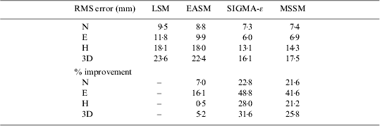
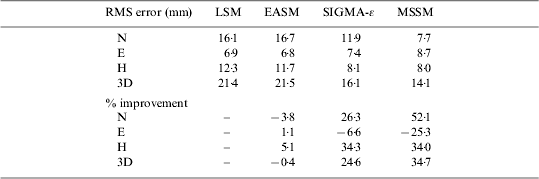
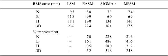
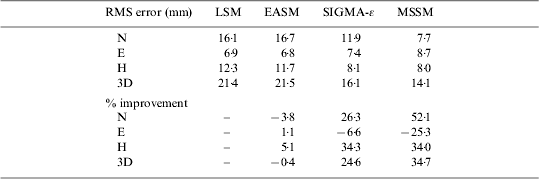
4·3. Multipath mitigation stochastic models. The RMS Northing, Easting, height, and three-dimensional (3D) positioning errors of the position solutions using the stochastic models for the LCPC and Nottingham datasets are tabulated in Tables 5 and 6, respectively. The percentage improvements are relative to the standard least squares solution LSM, which has an unit variance (without stochastic model).
RMS Northing, Easting, height, and 3D errors and their percentage improvement (when comparing with the results of unity/without stochastic model) of the tested stochastic models in the LCPC dataset.
RMS Northing, Easting, height, and 3D errors and their percentage improvement (when comparing with the results of unity/without stochastic model) of the tested stochastic models in the Nottingham dataset.
The LCPC results show that all the stochastic models have better positioning accuracies when compared with the standard least squares method. However, the SIGMA-ε model shows better results than either of the other two stochastic models. We believe that the reason the MSSM results are not better than the SIGMA-ε results in this dataset is that the pseudorange multipath errors in L1 and L2 are almost “in-phase” with each other, and also with the carrier-phase multipath errors. They are also almost “out-of-phase” with the SNRs. This phenomenon was noted in (Betaille et al, 2006), which also analysed the same dataset, and contradicts the receiver theory discussed in (Lau and Cross, Reference Lau and Cross2006b). However, it is good to have this exceptional dataset for the assessment of this new stochastic model so that we can understand its limitations.
Regarding the results of the Nottingham dataset, the elevation angle based model (EASM) shows a little deterioration (0·4% in 3D positioning accuracy) when compared with the standard least squares method. The deterioration in Easting component for SIGMA-ε and MSSM models are probably due to the weakened satellite geometry. Nevertheless, the MSSM result shows the best positioning accuracy when compared with the other two stochastic models in this dataset. These results are extremely encouraging, especially since the experimental set-up probably represents a more common practical situation.
4.3. Ray-tracing method
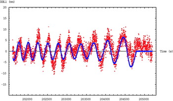
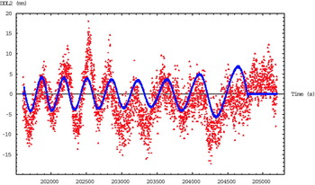
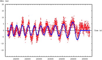
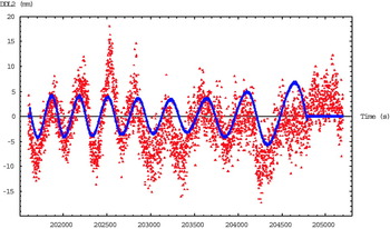
In the LCPC dataset, phase multipath errors were computed using the ray-tracing method described in Section 2.4. Satellite PRN02 was identified (by residual analysis of real data) as a satellite with significant multipath and comparisons have been made between the real and modelled DD residuals for this satellite, using the highest elevation satellite (PRN03) as the reference. Figures 20 and 21 show computed DD residuals along with the observed DD residuals for the GPS L1 and L2 data, respectively. The differences are mainly due to measurement noise and for most of the time are within ∼3 mm (the assumed nominal DD measurement noise (Kim et al. Reference Kim, Jang and Kee2004; Park et al. Reference Park, Kim, Lee, Park, Jee and Oh1998)), which is consistent with the expected level of noise for modern geodetic receivers (Brown and Wang Reference Brown and Wang1999; Gratton et al. Reference Gratton, Khanafseh, Pervan, Pullen and Warburton2004). We can therefore conclude that our model also predicts the amplitude of the multipath accurately as well as its phase and frequency. For those periods where the discrepancy is >3 mm, it is considered most likely that either the models for the damping factor and reflection are still incomplete, or that additional multipath occurred in that period.
Double difference residuals for PRN02 L1 data in the LCPC dataset; raw double difference residuals are in red and the modelled phase multipath errors (no measurement noise) are in blue.
Double difference residuals for PRN02 L2 data in the LCPC dataset; raw double difference residuals are in red and the modelled phase multipath errors (no measurement noise) are in blue.
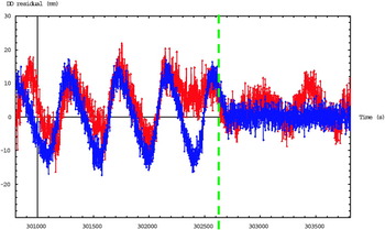
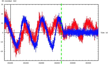
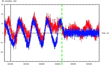
Regarding the Nottingham dataset, satellite PRN01 was identified (by residual analysis of real data) as a satellite with significant multipath, and comparisons have been made between the real and modelled DD residuals for this satellite, using the highest elevation satellite (PRN11) as the reference. Figures 22 and 23 show modelled DD residuals along with the observed DD residuals for the GPS L1 and L2 data, respectively. The right-hand sides of the green dotted lines in the figures are the un-modelled epochs, when no reflection was found by the ray-tracing in the generalised areas of the brick building. The elevation angle of the satellite varied from 30° to 45° during the time in which there were reflections.
Double difference residuals for PRN01 L1 data in the Nottingham dataset; raw double difference residuals are in red and modelled double difference residuals (with measurement noise) are in blue.
Double difference residuals for PRN01 L2 data in the Nottingham dataset; raw double difference residuals are in red and modelled double difference residuals (with measurement noise) are in blue.
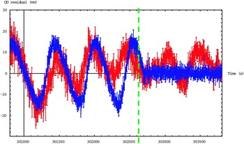
The results show that, apart from disagreements when the reflection point is near the edge of the building, the multipath model can predict very good amplitude and reasonably good phase for multipath errors. Possible reasons for the disagreement in the phase at some epochs are described in the discussion of the steel panel validation. This good agreement suggests that specular reflection is the dominant multipath error source even if the surface is rough.
5. DISCUSSION AND CONCLUSION
This paper describes the software-based phase multipath mitigation techniques investigated in the SPACE project so far. They are the SNR-based phase multipath estimation technique, antenna array technique, multipath mitigation stochastic models, and the ray-tracing method. The techniques have been tested with well-controlled real experimental and simulated data.
The investigations show that the SNR-based multipath error estimation algorithm can determine the phase multipath errors in static antennas reasonably well, apart from the sign problem. However, the algorithm does not perform very well when the real phase multipath error is less than about 1 cm. This is probably due to the other noise (white noise in receiver, signal propagation in space and tracking noise) contributing to the SNR being comparable to the multipath noise in SNR, leading to tracking problems in the ALNF and ACF.
From the simulation results on the antenna array technique, the technique works well at a permanent reference station, where the orientation of the antenna array in the satellite reference frame is known. Because of the importance of computing the single difference of the direct signals between the reference antenna and an auxiliary antenna in the antenna array, the algorithm using the modernised GPS and Galileo multiple-frequency data shows an average about 30% improvement on the multipath error estimation accuracy when comparing with using the current reliable GPS L1 data. This is because of the averaging effect of more GNSS signals on multipath errors in least squares position estimation for the determination of the orientation of the antenna array in the satellite reference frame. The results also show that the performance of the technique using 6 cm antennas' separation is always better than using 9 cm antennas' separation. It shows that the technique works better when the antennas are closer and hence the correlation of multipath errors at the antennas is stronger. However, antennas' separation of less than one third of the observing carrier wavelength may suffer from the mutual coupling effect in practice.
Three multipath mitigation stochastic models have been described and tested with real datasets. The three models are the satellite elevation angle based model, the SIGMA-ε model, and the modified SNR-based stochastic model (MSSM). Positioning errors obtained using all three models are compared with those from standard least squares solutions (i.e. using a unit matrix from the stochastic model). An improvement in accuracy of between 26% and 35% has been found using the new method with these datasets, with the level of improvement depending on the amplitudes and frequencies of multipath errors, and the phase coherence of SNRs and pseudorange multipath errors. Test results of the MSSM model are always better than those using the simple elevation angle based model, however, they are not better than the SIGMA-ε model in the LCPC dataset because of the unexpected phase coherence of L1 and L2 pseudorange multipath errors and carrier-phase multipath errors.
The ray-tracing method has been verified by comparing modelled multipath errors with observed multipath errors in two sets of experiments, one based on reflections from a smooth steel panel and the other on reflections from a brick building. The real and modelled results from the steel panel experiment are in excellent agreement – perfectly in phase with only small disagreements in amplitude (always less than 5 mm and usually less than 2 mm). If the model had been used to correct for this multipath the results would always be improved. The real and modelled results from the brick building experiment are in good agreement in amplitude. There are, however, some disagreements in phase at some epochs.
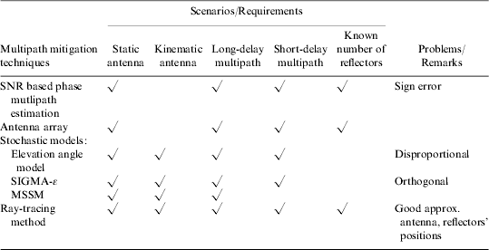
Different techniques have different multipath mitigation efficiencies, however some techniques are only suitable for certain multipath scenarios. SNR-based phase multipath estimation technique needs the sinusoidal pattern of SNR data, therefore this technique is only suitable for static antennas. Besides, this technique requires knowing the number of multipaths in a satellite's measurement in order to estimate the sine curves in the SNR measurement, which consists of other noise. Moreover, the correction (90° shift in Equation 2) to the orthogonality between SNR and phase multipath error may lead to sign error (180° shift in phase) in the estimated phase multipath error. The antenna array technique may not work well for RTK applications because the orientation of the antenna array in the satellite reference frame needs to determine accurately in real-time. Moreover, this technique requires knowledge of the number of multipaths in a satellite's measurement to allow the estimation of the multipath parameters using an Extended Kalman Filter. However, there may be insufficient observation epochs for the filter to converge the multipath parameters estimation because the reflectors may not be the same between epochs. Regarding the multipath mitigation stochastic models, our new MSSM method does not have the problems/errors of disproportion between satellite elevation angle and phase multipath error in the elevation angle based stochastic model, and orthogonality between SNR and phase multipath error in the SIGMA-ε model. However, it is difficult to detect the presence of multipath in phase data before applying the modified SNR stochastic model. The approach of using the determined dual-frequency pseudorange multipath errors to detect the presence of multipath in phase data described in Section 2.3.3 has problems of coherent dual-frequency pseudorange multipath errors and coherent pseudorange multipath error and phase multipath error, as shown in the LCPC dataset, when the differential path delay is short (usually caused by close reflectors). The multipath contaminated SNR is always orthogonal to phase multipath error but the multipath contaminated SNR is not in-phase with pseudorange multipath error when short delay multipath occurs. This leads to erroneous detection of the presence of multipath in phase data which causes incorrect weighting of the measurement. The authors are investigating a robust approach for detection of the presence of multipath in phase data before applying the modified SNR stochastic model. Therefore, the current MSSM algorithm is not applicable for short delay multipath. Finally, the ray-tracing technique can be used to model phase multipath errors in all multipath scenarios provided that reflector and antenna properties and the antenna and reflectors' positions are known accurately. The performance of this method depends on the accuracies of the required information described above. Therefore, this technique is very suitable for modelling phase multipath errors at static antennas such as those at base stations, and kinematic antennas in repeated trajectories such as those for positioning of LEO satellites and trains (multipath from the antenna carrying platforms). The multipath scenarios and requirements for each technique are summarised in Table 7.
Summary of some software-based phase multipath mitigation techniques for different multipath scenarios, and the limitations of the techniques.
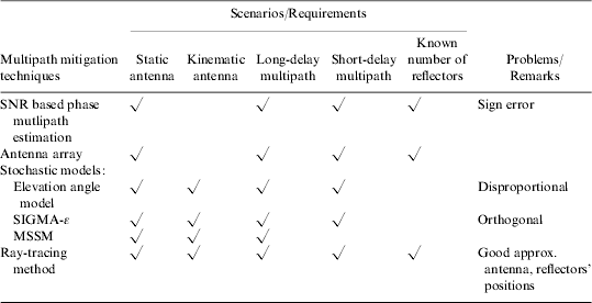
In order to mitigate multipath errors for all difficult environments, the multipath mitigation techniques described in this paper may be combined to tackle all the multipath scenarios listed in Table 7 but without the limitations or problems in their stand-alone mode. The integration of our two novel multipath mitigation techniques – MSSM and ray-tracing method will be able to mitigate short- and long-delay multipath for static and kinematic antennas; the ray-tracing method mitigates multipath errors from the antenna carrying platform while the MSSM mitigates the other medium- and long-delay multipath errors. A system needed to provide high-accuracy positioning in all conditions and environments, the integration of multipath mitigation techniques and an artificial intelligence system for selection of the techniques may be required.
Acknowledgment
The authors are grateful to David Bétaille for the provision of the experimental data collected at LCPC and used for testing the algorithm in this paper.
The work described in this paper has been carried out as part of SPACE (Seamless Positioning in All Conditions and Environments), which is a UK Engineering and Physical Sciences Research Council (EPSRC)-funded Pinpoint Faraday flagship project. It is led by four of the leading academic GNSS research centres in the UK and supported by industrial partners. The academic team members are: CAA Institute of Satellite Navigation at University of Leeds, Department of Civil and Environmental Engineering at Imperial College London, Department of Geomatic Engineering at University College London (UCL), and Institute of Engineering Surveying and Space Geodesy at the University of Nottingham. The industrial partners are The Civil Aviation Authority, EADS Astrium, Leica Geosystems, Nottingham Scientific Ltd, Ordnance Survey, QinetiQ and Thales Research and Technology. The primary aim of SPACE is to undertake the basic research needed to build a prototype GNSS-based positioning system that can deliver cm-level accuracy positioning everywhere and at all times. Multipath mitigation is one of its main research thrusts.