Introduction
The emergence of 5G communication technology strongly promotes applications such as Internet of Everything [Reference Dixit and Kumar1], health monitoring [Reference Zhao, Zhang, Lu, Chu, Chen, Liu and Li2], telemedicine [Reference Alqadami, Nguyen-Trong, Mohammed, Stancombe, Heitzmann and Abbosh3], and wearable antennas have become a hot spot for research. With the continuous development of antenna industry, realizing miniaturization [Reference Wang, Xuan, Jiang, Li and Wang4], low profile [Reference Nikam, Kumar, Baidya and Ghosh5], and high gain [Reference Ibrahim and Ali6] has been the direction of antenna innovation. To guarantee the safety when apply to the human body, having the characteristics of low human radiation and high front-to-back ratio (FBR) [Reference Pei, Du, Shi and Peng7] is importance.
There are many studies on wearable antennas. Many researchers have proposed wearable antennas using Rogers 3003 [Reference Pei, Du, Shi and Peng7, Reference Yadav, Ali and Yadav8], Rogers 4003 [Reference Mu and Ren9], felt [Reference Muhammad, Abdulkarim, Abdoul and Dong10], textile [Reference Das, Basu, Mandal, Mitra, Augustine and Mitra11], etc. as dielectric substrates in order to explore the properties of various materials. Meanwhile, in order to make wearable antennas more widely used and flexible in applications, antennas with multifrequency [Reference Dang, Chen, Zhu and Fumeaux12] and broadband [Reference Varkiani and Afsahi13] characteristics are also hot spots of research. The majority of them cover the wireless body area network (WBAN) band’s 2.4 and 5.8 GHz.
In wearable antenna design [Reference Kumkhet, Rakluea, Wongsin, Sangmahamad, Thaiwirot, Mahatthanajatuphat and Chudpooti14–Reference Huang and Liu23], it is critical to ensure safety when applied to the human body, primarily in terms of a low specific absorption rate (SAR) value and a high FBR. In terms of reducing human body radiation, common solutions are loaded electromagnetic band gap (EBG) structures [Reference Kumkhet, Rakluea, Wongsin, Sangmahamad, Thaiwirot, Mahatthanajatuphat and Chudpooti14, Reference Nie, Xuan and Ren15], metamaterials (MTM) [Reference Das, Basu, Mandal, Mitra, Augustine and Mitra11], or artificial magnetic conductor (AMC) structures [Reference Yang, Yu, Yang and Zhao16–Reference Saha, Mitra and Parui18, Reference Zu, Wu, Yang, Li and Liu22] on the back of the antenna to increase the antenna gain and FBR value while lowering the antenna’s backward radiation. In reference [Reference Chaturvedi, Kumar and Althuwayb19], a dual-band dual-polarization antenna has the characteristics of high isolation and low SAR values with Substrate Integrated Waveguide (SIW)cavities.
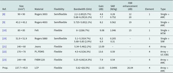
Recently, many wearable antenna arrays are proposed, where researchers have used flexible materials such as polyethylene terephthalate [Reference Farooq, Iftikhar, Fida, Khan, Shafique, Asif and Shubair20], jeans [Reference Reddy, Vakula and Kumar21], polydimethylsiloxane (PDMS) [Reference Zu, Wu, Yang, Li and Liu22], and polytetrafluoroethylene (F4BM) [Reference Huang and Liu23] in the design of antenna array. In reference [Reference Farooq, Iftikhar, Fida, Khan, Shafique, Asif and Shubair20], the author proposed a flexible antenna array by CPW feed, making it easier to integrate into biomedical systems. The antenna is made up of four units with a peak gain of 10 dB. In reference [Reference Reddy, Vakula and Kumar21], a wearable four-element antenna array with jeans substrate is designed, and its maximum gain can reach 13.09 dB. The antenna array proposed in reference [Reference Zu, Wu, Yang, Li and Liu22] is loaded with a uniplanar compact EBG (UC-EBG) reflector, the maximum antenna gain is 13.6 dB, and the SAR is 0.59 W/kg at 6 GHz, but the overall size is large. In reference [Reference Huang and Liu23], a dual-polarized flexible antenna array is proposed, which are loaded with AMC structures. However, the final simulated antenna gain is only 7.9 dB. Under the current research, with the development of communication systems, wearable antennas with smaller gains and larger size cannot meet the needs of diversified applications. Therefore, it is a challenging work to design a compact flexible antenna array with the characteristics of high FBR, high gain and low SAR.
This paper presents a wearable antenna array for WBAN 5.8 GHz loaded AMC structure. The antenna operates in the 5.62–6.0 GHz band with a relative bandwidth of 6.5%. The final size of the antenna is 137.7 × 45.9 mm2. The AMC structure and the antenna array are composed on 0.1 mm thick flexible liquid crystal polymer (LCP) substrate. The back-loaded AMC structure enables the antenna to reach a gain of 12.03 dB at 5.8 GHz and a FBR value of 27.48 dB. The SAR value is reduced from 0.7906 to 0.0496 W/kg. The results show that the antenna has good application prospects in the field of wearable antennas. The innovations in the paper are: the antenna array is low profile and flexibility; the overall size of the antenna is reduced by miniaturized design; an AMC structure is loaded underneath the antenna array, which can effectively enhance the gain and FBR, and reduce the SAR value of the antenna.
Antenna design
Antenna element design
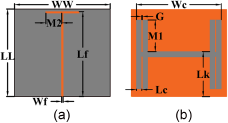
Figure 1 shows the exact structure of the antenna element. A 0.1 mm thick LCP dielectric substrate with a loss tangent of 0.002 and a relative permittivity of 2.9 is used in the suggested antenna. The front is a 50Ω feeder, and the background has an engraved H-shaped slot. The H-shaped slot is added to improve the impedance bandwidth of the antenna. The overall size of the element is 18 × 16.5 mm2, and the simulation bandwidth covers 5.5–6.21 GHz. The optimized geometric parameters of the proposed antenna are as follows: LL = 16.5 mm, WW = 18 mm, H = 0.1 mm, Wc = 16 mm, Lf = 16 mm, Lk = 8.5 mm, M1 = 6 mm, M2 = 3 mm, Wf = 0.26 mm, Lc = 1 mm, G = 0.1 mm.
Antenna element structure diagram. (a) Top view (b) Back view.

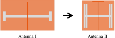
The antenna element design process is given in Fig. 2. Antenna I is the first design step, the front is a 50Ω feed line, and the background has an engraved H-shaped slot, which can expand the bandwidth of the antenna. Antenna II is the second design step, the original H-slot is changed to a double H-slot for reducing the size of Antenna I, and the feed line is extended to both sides to form a T-shaped structure. Through miniaturization, the final antenna element’s total size has been lowered by 45%.
Design process of antenna element.

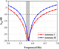
The S-parameters for both two antennas are presented in Fig. 3. Antenna I covers 5.31–6.45 GHz, and Antenna II covers 5.5–6.21 GHz. After miniaturization, the bandwidth of the antenna is shortened by 0.43 GHz, but the reduced bandwidth of Antenna II still covers the desired frequency band. As the size of Antenna II is smaller, so it is chosen as the unit of the antenna array.
S11 of the two antennas.

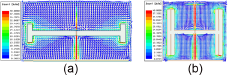
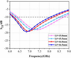
In Fig. 4 the current distribution of Antenna I and Antenna II at 5.8 GHz is given. From the figure we can notice that the current is mainly concentrated around the slit and feedline. The antenna’s miniaturized design reduces the antenna’s size while increasing the current path, which ensures that the antenna resonates at 5.8 GHz. Figure 5 gives the relationship between the length (Lf) and the antenna’s resonance frequency. In the figure, when the Lf becomes larger, the antenna’s electrical length increases, and the resonant frequency is more biased toward the low frequency.
Current distribution diagrams. (a) Antenna I (b) Antenna II.

The influence of Lf on S11.

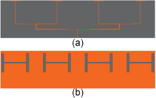
Antenna array structure. (a) Top view (b) Back view.

Antenna array
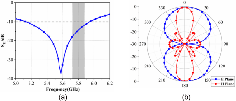
Four antenna elements and the power divider are combined to form a quaternary antenna array, as shown in Fig. 6. The power divider is designed using the Chebyshev unequal division method to increase the antenna’s directivity. Overall antenna dimensions are 111 × 27 mm2, and the spacing between adjacent units is 30 mm. Figure 7(a) displays the antenna array’s S11 parameter, which covers 5.13–5.94 GHz. As the antenna resonance frequency will be shifted to the high frequency by adding AMC structure, so the antenna resonance frequency is set at 5.58 GHz. At 5.8 GHz, the realized gain and side lobe are 9.7 and −17.5 dB, respectively. The radiation pattern is shown in Fig. 7(b).
Antenna array performance. (a) S11 parameter (b) Radiation pattern.

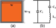
The proposed AMC unit. (a) AMC unit model (b) Equivalent circuit model.

AMC unit
To lower the radiation toward the human body as well as to increase the FBR of the antenna, an AMC structure reflector is loaded on the back of the antenna array. When electromagnetic waves are incident, the AMC structure has a high surface impedance, which can effectively reduce the backward radiation. It is also characterized by in-phase reflection, where the incident and reflected waves are superimposed to increase the forward gain.
In Fig. 8(a), the AMC reflection element is printed onto a 0.1 mm thick LCP dielectric substrate in the shape of a square patch. The metal ground plane completely covers the dielectric board’s rear surface. Figure 8(b) displays the AMC array’s corresponding circuit model. The AMC structure is equivalent to a LC parallel circuit. The gap between the patch and the ground will produce an equivalent capacitance C 1, and there is also an equivalent capacitance C 2 between two adjacent patches. The square patch on the upper layer generates an equivalent inductance L 1.
The proposed AMC structure is an evolution of the traditional mushroom-shaped structure. The size of AMC structure can refer to the following formula [Reference Ashyap, Dahlan, Abidin, Abbasi, Kamarudin, Majid, Dahri, Jamaluddin and Alomainy24]:
 \begin{equation}{L_1} = {\mu _0}t\end{equation}
 \begin{equation}{f_0} = \frac{1}{{2\pi \sqrt {{L_1}{C_1}} }}\end{equation}
 \begin{equation}{C_1} = \frac{{{\varepsilon _0}\left( {1 + {\varepsilon _r}} \right)w}}{\pi }cos{h^{ - 1}}\left( {\frac{{w + g}}{g}} \right)\end{equation}
where  ${L_1}$ and
 ${C_1}$ stand for the AMC structure’s inductance and capacitance,
 ${\varepsilon _0}$ is the dielectric constant of free space,
 ${\varepsilon _r}$ is the dielectric constant of the substrate,
 $w$ is the width of the AMC square patch,
 $g$ is the distance between the AMC patch,
 ${\mu _0}$ is the permeability of the dielectric substrate,
 $t$ is the dielectric substrate’s thickness, and
 ${f_0}$ is the operating frequency of the AMC structure. The optimized dimensions of the AMC element are as follows: w = 14.6 mm, g = 0.35 mm, t = 0.1 mm.
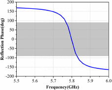
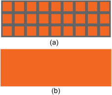
Figure 9 shows the design model and reflection phase characteristics of the AMC element, which has a reflection phase bandwidth of 60 MHz, covering 5.77–5.83 GHz. A model diagram of the proposed AMC array is given in Fig. 10. This AMC array consists of 9 × 3 units and the backside is completely covered by a metal ground.
Reflection phase of the AMC unit.

The structure of the AMC array. (a) Top view (b) Back view.

Antenna array loaded with AMC structure
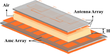
The 9 × 3 AMC structure is loaded based on the antenna array, which is 11.8 mm away from the antenna array. During the simulation, the air-filled gap is between the array and AMC reflector. After loading the AMC reflector, the antenna’s total dimensions are 137.7 × 45.9 mm2. The structure is shown in Fig. 11.
The AMC-loaded antenna array model.

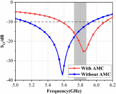
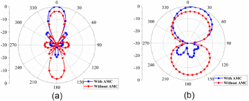
The comparison of antenna S11 parameters before and after loading AMC is displayed in Fig. 12. Between 5.57 and 6.11 GHz, the AMC-loaded antenna’s S11 is below −10 dB and covers the WBAN operating frequency band of 5.725–5.875 GHz. The relative bandwidth reaches 9.2%. Figure 13 shows the radiation pattern of the antenna before and after loading the AMC reflector at 5.8 GHz. From the figure, we can conclude that the antenna’s backward radiation is significantly reduced after loading the AMC structure, and the forward gain increases. At 5.8 GHz, the antenna’s gain is 13.5 dB., which is 3.8 dB higher than that without the AMC reflector structure. Furthermore, the FBR improves by 26.04 dB.
S11 parameters of the antenna.

Radiation patterns with and without AMC structure at 5.8 GHz. (a) E plane (b) H plane.

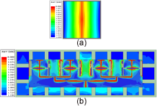
The surface currents at 5.8 GHz for the AMC unit and the array antenna loaded with the AMC structure are shown in Fig. 14. The maximum current density is observed at the floor gap section and at the front feeder. At the same scale, the surface current density of the 9 × 3 AMC structure placed behind the antenna array is significantly reduced and the back radiation is effectively reduced.
Surface current distribution. (a) AMC unit (b) Antenna array with AMC structure.

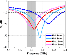
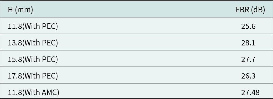
The effect of the distance H between the AMC and the antenna as well as the number of AMC units on the performance of the antenna is explored. Figure 15 gives the S11 parameters of the antenna after loading the AMC structure at varying values of H. As H increases, the resonant frequency point moves to the left. The FBR and realized gain values of the antenna at different H are given in Table 1. When H is taken as 11.8 mm, the S11 is from 5.58 to 6.1 GHz, the antenna realized gain is 13.5 dB, and the FBR is greatly improved to 27.48 dB, which can effectively reduce the radiation to the human body, so the optimum value of H is chosen as 11.8 mm.
The effect of H on S11 parameters.

The effect of H on FBR and realized gain values

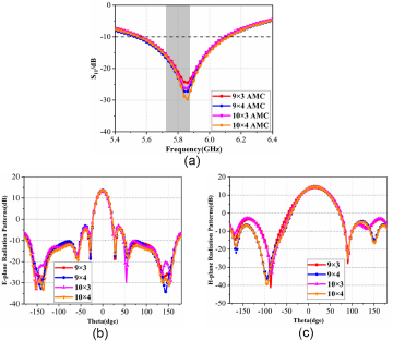
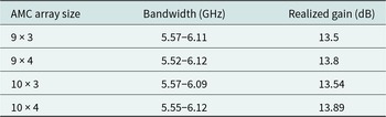
To investigate the impact of varying ACM structures on the antenna, Fig. 16 provides the S11 parameters and radiation patterns of the antenna loaded with various AMC structures. As the number of AMC units increases, the impedance matching of the antenna gets better and the S11 value decreases gradually. The bandwidth and realized gain of the antenna with different sizes are given in Table 2. From the table it is clear that the bandwidth of the antenna is almost constant. With the enhancement of the AMC reflector plate size, the gain is improved. From Fig. 16(b) and (c), the EH-plane radiation patterns of the antenna are almost constant. Considering both size and performance, the AMC array size is finally selected 9 × 3.
Effect of loading different number of AMCs on antenna performance. (a) Effects on S11 parameters (b) Effects on E-plane radiation (c) Effects on H-plane radiation.

The performance of antennas with different numbers of AMC units
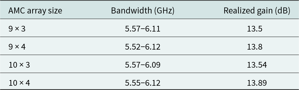
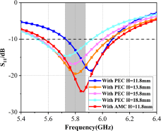
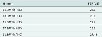
Figure 17 shows the S11 values of the antenna loaded by the AMC and Perfect Electric Conductor (PEC)structure, and the PEC reflector is the same size as the AMC structure. From the figure, it can be seen when the distance between the antenna and the PEC structure is gradually increased, the resonant frequency point moves to the left. When the distance H is 11.8 mm, the S11 of the antenna loaded with AMC structure is better than PEC structure. The FBR values of the antenna for different values of H are given in Table 3. When the H is 11.8 mm, the antenna loaded AMC structure is able to achieve higher FBR values than PEC structure. When the antenna is loaded by the PEC structure, the FBR value increases with the enhancement of H, but the space size is larger. In summary, the antenna loaded AMC structure can achieve a higher FBR value with a small size.
Simulated S11 of the antenna supported by the AMC and PEC structure.

The FBR values for different values of H
Measured results and analysis
S11 parameter
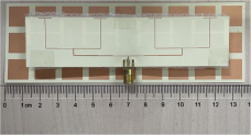
The proposed antenna was fabricated, as shown in Fig. 18. In a microwave anechoic chamber, the return loss and far-field radiation patterns of the antenna were measured.
Antenna physical diagram.

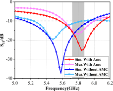
The return loss of both the standalone antenna array and the antenna array loaded with an AMC structure was tested using a vector network analyzer. Figure 19 shows the measurement results. The measured S11 of the antenna array without AMC structure covers 5.22–5.88 GHz. After loading the AMC structure, the S11 covers 5.62–6 GHz, achieving a relative bandwidth of 6.5%. Compared with the simulation data, the measured return loss and bandwidth exhibit some deviations, as well as the measured resonant frequency shifts to 5.8 GHz. These differences in measurement results may be due to machining errors and the test environment.
Comparison of measured and simulated data.

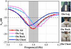
The antenna was placed on the back, chest, and legs of the human body, to test its performance. The measured S11 is shown in Fig. 20, which is less than −10 dB in the required frequency band of 5.725–5.875 GHz, indicating good performance.
Measured S11 parameters on different body parts.

Far-field radiation
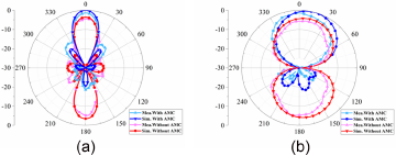
The radiation pattern and gain of the antenna are tested in the far-field darkroom. Figure 21 displays the antennas’ 5.8 GHz simulated and measured radiation patterns. From the figure we can see that the test results are basically consistent with the simulation results. The antenna’s backward radiation is effectively reduced. After loading AMC, the simulated side lobe of the antenna is −17.6 dB, and the measured side lobe can only reach −13.1 dB due to the influence of test error.
Far-field radiation patterns at 5.8 GHz. (a) E plane (b) H plane.

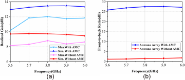
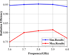
In Fig. 22(a), the measured and simulated gain comparison of the antenna with and without AMC structure is given. After loading the AMC array, the gain is increased from 8.8 dB to 12.03 dB at 5.8 GHz, which is increased by 3.23 dB. The measured gain is reduced by about 1.5 dB compared with the simulation results. The variance in measurement and environmental uncertainty is the reason for the deviation of the results. In Fig. 22(b), the FBR value of the antenna array without AMC structure at 5.8 GHz is 1.44 dB. After loading AMC, the FBR becomes 27.48 dB at 5.8 GHz. In Fig. 23, the radiation efficiency plot of the antenna loaded with AMC structure is given. In the simulation results, the radiation efficiency is over 90%. The measured radiation efficiency of the antenna is higher than 80% within the desired frequency band 5.725–5.875 GHz, which provides good radiation results. The discrepancy between the over 90% simulated radiation efficiency and the smaller 80% measured radiation efficiency due to factors such as machining errors in processing the antenna, testing errors, and the environment surrounding the antenna during testing.
Comparison of antenna array performance with and without AMC. (a) Realized gain (b) FBR value.

Radiation efficiency of antenna loaded AMC structure.

SAR evaluation
As wearable device, the SAR of the antenna needs to be evaluated. The SAR value is a parameter to measure the amount of electromagnetic radiation energy absorbed by a substance. The US federal standards require that SAR values are less than 1.6 W/kg, while the European federal standard is not more than 2 W/kg.
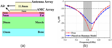
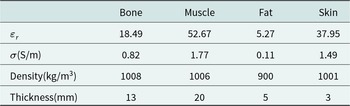
Figure 24(a) shows a simulation model of SAR values based on 10 g of human tissue. A four-layer human tissue model is constructed in HFSS, which is skin, fat, muscle, and bone from the surface to the inside. The distance between the antenna array and human model is 3 mm in the simulation. Figure 24(b) shows the simulated S11 of the antenna with and without the human body. Since the human model is also a medium when placed on a human body model for simulation, the S11 becomes worse, but the operating frequency band is almost unaffected and can cover 5.55–6.15 GHz. The electromagnetic properties of the layers of the mannequin are shown in Table 4.
SAR value simulation. (a) Simulation model (b) S11 parameters.

Electromagnetic properties of various human tissues

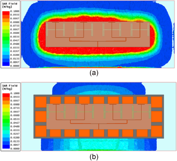
Figure 25 shows the simulation results of the SAR value at 5.8 GHz. The SAR values with and without AMC structure are compared in the figure. According to the results, SAR field of antenna array on the human body with AMC structure is significantly reduced.
The changes of SAR value without and with loading AMC. (a) SAR value without AMC (b) SAR value with AMC.

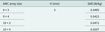
Table 5 shows the effect of the size of the AMC array on SAR values. From the table it can be seen that the larger the size of the AMC array, the lower the SAR value. The SAR values with varying H are discussed in Table 6. It can be seen that the larger the distance H from the antenna to the human body, the smaller the SAR value.
The effect of AMC array size on SAR values

The effect of H on SAR values

Performance comparison
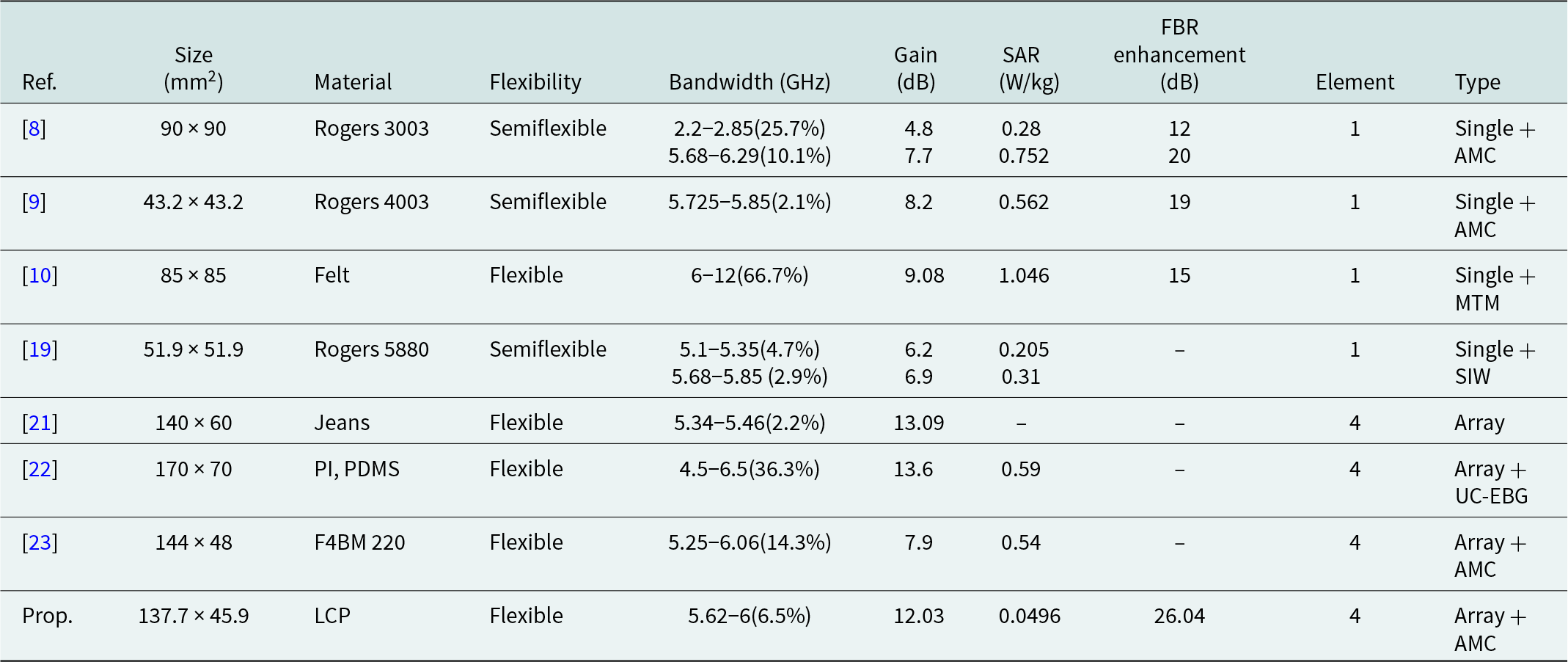
The performance comparison between the proposed wearable antenna array loaded with AMC and the previously proposed antennas is given in Table 7. In references [Reference Yadav, Ali and Yadav8–Reference Muhammad, Abdulkarim, Abdoul and Dong10, Reference Chaturvedi, Kumar and Althuwayb19], a single antenna loaded reflector design is used such as AMC, MTM, and SIW, and the gains of the antennas are less than 8.2 dB. In reference [Reference Reddy, Vakula and Kumar21], wearable antenna without AMC structure have narrow bandwidth, and the FBR values aren’t presented. In reference [Reference Zu, Wu, Yang, Li and Liu22], the antenna is loaded with UC-EBG structure to achieve wide bandwidth and high gain. However, its size is large and its SAR is 0.59 W/kg at 6 GHz. In reference [Reference Huang and Liu23], the final simulated gain of a dual-polarized antenna array with AMC structures is only 7.9 dB. In summary, the wearable antenna array with loaded AMC structure proposed in this paper is characterized by low SAR, high FBR, high gain, and compact size.
Comparison of antenna performance
Conclusion
This paper presents a compact, low SAR, high gain, high FBR wearable flexible antenna array. The antenna operates at 5.8 GHz and covers 5.62–6 GHz. The antenna array gain is 12.03 dB at 5.8 GHz after loading the AMC structure, an improvement of 3.23 dB. At the same time, the FBR can reach 27.48 dB. The antenna’s SAR value is only 0.0495 W/kg, which is far below the standard value. The compact flexible antenna array with low SAR, high FBR, and high gain is suitable to human health monitoring, human wireless communication, and telemedicine applications in the WBAN band.
Competing interests
The authors report no conflict of interest.

Jun Chuwas born in Jiangsu, China in 1999. She received the B.S. degree from the Shanghai University of Electric Power in 2021. She is currently pursuing the M.S degree in College of Electronics and Information Engineering, Shanghai University of Electric Power. Her research interests include antenna array and multiband antenna.

Chengzhu Du was born in Haikou, Hainan Province, China. She received the B.S. degree from the Xidian University, M.S. degree from Nanjing University of Posts and Telecommunications and PhD degree from Shanghai University, in 1995, 2003, and 2012, respectively, all in electromagnetic wave and microwave technology. She is currently an associate Professor of Shanghai University of Electric Power. Her research interests include flexible antenna, multiband and wideband antennas, and MIMO technologies.

Haifeng Shu was born in Sichuan, China in 1998. He received the B.S. degree from the Shanghai University of Electric Power in 2021. He is currently pursuing the M.S degree in College of Electronics and Information Engineering, Shanghai University of Electric Power. His research interests include antenna array and wearable antenna.