I. INTRODUCTION
Direct conversion receiver (DCR) architecture is widely used in modern wireless communication systems essentially for its high integration level, resulting in a lower cost and smaller size. The main well-known difficulties of DCRs are baseband co-located noises essentially linked to flicker noise, dc offsets, and second-order intermodulation distortion (IM2), all of which corrupt the desired signal and strongly degrade the receiver sensitivity. Although both first ones can be mitigated by high pass filtering in wideband applications [Reference Razavi1], IM2 still remains the most critical phenomena.
IM2 power linked to any interferer depends on its power level and second-order intercept point (IP2) level, which indicates a figure of merit for IM2 distortion compensation. So to reduce IM2 distortion, three approaches are possible:
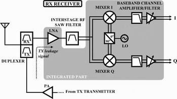
• Filtering of the strong interferer(s) before being affected by the main IM2 contributor blocks. For instance, 3G WCDMA DCR mostly used a surface acoustic wave (SAW) interstage filter to essentially attenuate the transmit signal (TX) leakage (Fig. 1). Despite of its high rejection, such an external filter does not meet the system integration constraints. The two following techniques are more suitable.
• Cancellation of IM2 distortion component. Compensation techniques have already been investigated [Reference Chen, Huang, Wen and Chen2, Reference Valkama, Ghadam, Anttila and Renfors3]. Assume that the wanted signal s(t) is corrupted by a strong interference I(t). The general method consists in extracting this latter thanks to an adaptive filter (AF) and then subtracting it from the signal observation s(t) + I(t). This method requires a reference of I(t) as input of the AF, so an accurate model of the second-order non-linearity, and also an additional path containing the AF from which the compensation is performed. Moreover, performance depends on certain signal assumptions. The need of a reference for each of any strong interferer limits the use of that technique, especially for complex systems as 3G transceivers (multimode, multiband, and multistandard). Indeed, exposed to the system cohabitation issue and technologically limited by RF front-end filtering, 3G receivers suffer from new interferers, which also contribute to IM distortion.
• Improvement of IIP2 parameter level via a calibration technique. In a DCR, the major IM2 distortion source is the down-conversion mixer. IM2 introduced by the low noise amplifier is usually filtered out by an AC coupling. IM2 distortion comes from nonlinearity and different mismatches in parts of the differential mixer design. So the common idea of IP2 calibration techniques is to intentionally introduce a calibrated mismatch. For instance, the calibration scheme presented in [Reference Kivekas, Parssinen, Ryynanen, Jussila and Halonen4] is based on an adjustment of the load resistors. That kind of calibration is operated at production step. In [Reference Barré and Ozenne5] a solution is proposed to automate the calibration at the system start up. However, IIP2 level is sensitive to system variations as supply voltage, LO frequency, and temperature, which will shift the optimum calibration. So an automatic and dynamic calibration, which means working during the reception of the wanted signal, is mandatory [Reference Darabi, Kim, Chiu, Ibrahim and Serano6, Reference Dufrêne, Boos and Weigel7]. This concept is challenging in portable devices, especially for 3G WCDMA transceivers in which no free operation time is available.
Typical architecture of the 3G WCDMA DCR.

This paper describes a perturbance-based algorithm as part of an automatic IP2 calibration system. This algorithm can be used to track the optimum IIP2 and make the future complete calibration system dynamic, i.e. operating online.
The paper is organized as follows. Section 2 deals with mixer mismatch influences on IIP2 performance and an example of IIP2 requirement for 3G WCDMA DCRs. Section 3 describes the used calibration technique and the first IM2 measurements. Section 4 presents a perturbance-based algorithm for tracking the optimum IIP2 level, and section 5 gives the measurement results.
II. SECOND-ORDER DISTORTION FROM A DIFFERENTIAL MIXER
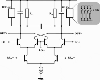
In a DCR, many mechanisms are responsible for the generation of IM2 products [Reference Manstretta, Brandolini and Svelto8, Reference Kivekas, Parssinen and Halonen9], which essentially occur in the mixer block. (Figure 2 describes the widely used Gilbert cell type mixer in DCRs considering a double-balanced topology.)
Schematic of the used tunable mixer for an IIP2 calibration technique.

In a perfectly balanced mixer, the desired RF signal is downconverted. The equivalent differential low-frequency IM2 products are fortunately upconverted around the LO frequency and the equivalent common-mode IM2 products are canceled out at the mixer differential output. Part of that low-frequency IM2 current directly leaks at the mixer output around the baseband, due to the following mismatches in the three different mixer stages:
– mismatches in the switching core linked to the nonperfect hard-switching (slow LO rise and fall time) and to the low deviation of the LO duty cycle from 50%,
– mismatches in the mixer load linked to the resistor mismatch but also to the baseband filter input impedance mismatch,
– mismatches in the transconductance stage due to the gain mismatch.
From a simplified behavioral model of the transconductance mixer, it is demonstrated in [Reference Dufrêne, Boos and Weigel7] that IIP2 is inversely proportional to those different mismatches.
A detailed parametric analysis shows that IIP2 is very sensitive to the mismatch in the load resistors ΔR. Indeed, a low imbalance in the loads strongly degrades the maximum IIP2 level. The IIP2 calibration technique based on an adjustment of the mixer loads will be introduced in the following section.
In DCRs the minimum required IIP2 is generally high. For example, let us consider a 3G WCDMA DCR. All RF parameters specifications can be calculated after analyzing the different test cases defined in the 3GPP standardization document [10]. Under certain assumptions on duplexer performances, the minimum determined IIP2 requirement referred to the LNA input is around 51 dBm (for the Band I). This strong requirement is due to the high power transmitted signal (TX) that leaks in the receiver chain and causes a severe IM2 problem. Without using interstage RF SAW filter and assuming good IM2 performance for LNA and baseband amplifier/filter, the corresponding IIP2 level of the mixer is obtained by only adding the LNA gain. An LNA gain of 15 dB leads to an IIP2 level of the mixer of +66 dBm, whereas the typical state-of-the-art value is only around +45 dBm.
III. IIP2 CALIBRATION SCHEME
By controlling a mismatch between the load resistors in order to compensate for all mismatches described previously, it is possible to improve the IIP2 level. Figure 2 gives a general view of the used calibrated mixer.
A binary weighted multiples of equal-sized resistors that can be switched on or off via several control bits are placed in parallel to mixer loads. This system of switched resistors is used for both I and Q channels, as the two mixers present different IIP2 characteristics and should therefore be calibrated separately.
The used mixer is a part of a dual-band CDMA transceiver implemented in a 0.25 µm BiCMOS process [Reference Charlon11]. It consumes 10 mA from a 2.7 supply, and has a typical gain of 14 dB, a noise figure of 5 dB, and the IIP3 is +5 dBm.
The IIP2 of each mixer sample is different depending on the process variations of the IC technology. For the used mixer, a final test on several samples shows that half of them presents an IIP2 level between +52 and +55 dBm, and the lower and higher IIP2 performance is +33 and +68 dBm, respectively.
The improvement of the IIP2 depends on the characteristics tuning range and resolution, which are beforehand fixed so as to cover all the measured mixer samples. The tuning range is ±5.62% from the nominal mixer load resistance value and a 7-bit resolution is adequate to achieve a significant improvement of the IIP2 (plus one bit for the selection of the positive or negative branch of the differential mixer).
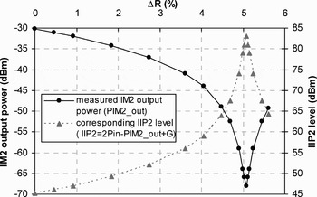
Figure 3 illustrates the measured IIP2 level as a function of the controlled imbalance in the mixer load resistors. Without calibration (ΔR = 0) the measured IIP2 is +45 dBm, whereas after calibration the achieved value is +83 dBm, corresponding to an improvement of +38 dB. This curve is obtained by using a basic two-tone test signal at the input and measuring the power of the low-frequency IM2 component at the output. The IIP2 level is then determined by using the relation P IM2_low_frequency_OUT = 2P 1tone_IN − IIP2 + Gain.
Measured IM2 power in function of ΔR and determination of its associated IIP2 level.

The direct tuning simultaneously increases the dc offset at the mixer output [Reference Kivekas, Parssinen, Ryynanen, Jussila and Halonen4]. To overcome this problem, the mixer outputs should be ac coupled. However, as previously mentioned, any dc offset has to be removed in DCRs and for CDMA/WCDMA system a high-pass filtering (implemented by ac coupling or a servo feedback loop) is suitable. Moreover, the imbalance introduced by the mixer loads is so small that it has a negligible effect on other performance parameters such as gain, noise, or IIP3 [Reference Kivekas, Parssinen, Ryynanen, Jussila and Halonen4].
The control of the switched resistors can be performed through a software application at the production stage. However, the optimum calibration point is dependant from several system variations (as supply voltage, temperature, or operating frequency). A new calibration should be run to determine a new optimum IIP2 point as soon as temperature variation is large or as soon as a communication should be established through a different channel where the center frequency is far from the previous one. This issue becomes critical as digital calibration techniques still need some signal processing from the micro-controller (or DSP chip) to operate properly: this is a heavy constraint since calculation power and availability of this micro-controller (or DSP chip) is limited. For instance, ref. [Reference Barré and Ozenne5] describes a digital solution to automate the calibration technique only when the portable device is powered on.
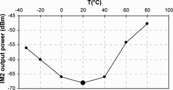
Figure 4 shows the impact of temperature on the previous static calibration. The optimum calibrated point previously determined at 20°C is strongly degraded.
Negative influence of temperature variation on an initial IM2 calibration at 20°C.

To overcome that optimum IIP2 drift in function of system variations, the automatic calibration system has to perform a dynamic correction, i.e. a continuous correction during the reception of the wanted signal.
IV. ALGORITHM OF OPTIMUM IIP2 TRACKING
To prevent the IIP2 drift as a function of system variations the tuning code has to be dynamically corrected. To perform that kind of online operation, a perturbance-based algorithm is proposed which when applied to existing static IP2 calibration (as the one previously described) will make it dynamic. For a future implementation, this algorithm has to be at first validated to show the feasibility of the approach. The algorithm is more suited to the digital IP2 calibration system based on an IM2 power detection. For instance, the system in [Reference Barré and Ozenne5] includes a basic two-tone test signal, and the produced low-frequency IM2 term is detected at the output of the receiver. The test signal level is limited to reduce the interferences with the wanted signal.
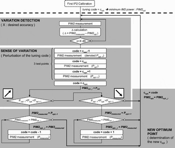
The algorithm principle is explained as follows (Fig. 5). Assume a static IP2 calibration performed at the system start up. After that operation the optimum tuning code is thereby known, and will be denoted c opt. The proposed algorithm realizes a dynamic correction of the calibration. It is supposed to work only around the optimal IM2 zone to perform a local tracking of the optimum IM2 point.
Flow chart of the perturbance-based algorithm for optimum IIP2 tracking.

It is essentially based on the three following steps (Fig. 5):
• In the first one, any consequent variation on the detected IM2 interference power is detected by calculating the difference between the new and old detected power at c opt.
• As soon as the difference is significant (which can be fixed at 0.5 dB for instance), the following step is to determine the sense of variation, i.e. on the decreasing or increasing slope of the IM2 output power curve presented in Fig. 3. This can be done by measuring the IM2 powers, respectively, at c opt − 1, c opt, and c opt + 1, where the perturbation 1 represents a one unity change of the resistor control code.
• Finally, the new optimum code is determined either by increasing the old optimum code c opt until measuring the optimum IM2 power in the case of a detected negative slope or by decreasing c opt in the case of a detected positive slope.
An important system condition at the origin of the definition of the algorithm is that the IM2 drift is much slower than the IM2 variation performed by the perturbance-based algorithm:

This condition is verified around the optimum IM2 zone where a quick calibration step (equivalent to a unity perturbation of the tuning code) corresponds to several dB change on the IM2 power measurement. This value is much more significant than the slow IM2 power drift due to system variations.
To check the algorithm behavior, a test bench has been set up, using the previous calibrated mixer of the receiver presented in [Reference Charlon11]. The algorithm is coded in ANSI C (from LabWindow). The communication with the receiver is done via a 3 wire-bus interface card. A basic two-tone test signal is injected at the input of the mixer, and the low-frequency IM2 component is measured from a spectrum analyzer via a GPIB bus. The system variation is provided by a strong temperature variation (from 20 to 60°C) and applied to the mixer previously calibrated at 20°C.
V. MEASUREMENTS RESULTS
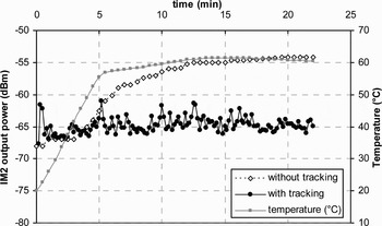
Figure 6 shows that without correction of the tuning code, the IM2 degradation is around 13 dB (from −68 to −55 dBm), whereas performing the defined algorithm leads to a tracking of the optimum IM2 level. The small reduction of the mean optimum IM2 level (−65 dBm instead of −68 dBm) is due to the noise of the power measurement device.
Measured IM2 performance with and without the specified algorithm of tracking in response to a temperature variation.

These results clearly show that the proposed algorithm can provide an online performance IIP2 improvement for a future implementation.
The easy concept of the algorithm gives a real advantage to a dynamic auto-calibration technique to come.
VI. CONCLUSION
DCRs suffer from second-order distortion linked to strong interferers and therefore require a high IIP2 level. In such receivers IM2 distortion is essentially generated by the downconversion mixer. High IIP2 level of the mixer is very difficult to achieve because it depends on the processing variations of the IC technology. The main mechanism of IM2 generation in a differential mixer is the combination of nonlinearity and mismatches in transconductor, switching, and load stages, which imbalance the mixer structure. Controlling a mismatch between the load resistors to compensate all these mismatches improves the IIP2 level. Such a calibration technique uses a switched resistors system in parallel to mixer loads digitally tunable. In a well-isolated BiCMOS mixer, calibrated with a tuning range of 5.62% from the nominal mixer load resistance by a 7-bit resolution, the achieved IIP2 level is around +83 dBm instead of the noncalibrated measured value of +45 dBm. However, IIP2 performance then degrades with system variations (supply voltage, LO frequency, temperature) during the receiver working. To overcome any optimum IIP2 drift after calibration, a perturbance-based algorithm is developed in order to track the optimum IM2 level. Applied to an automatic IP2 calibration system, it will give the possibility of dynamically correcting the code of calibration. Test and measurements indicate that the proposed algorithm can provide an online performance IIP2 improvement for a future implementation. This algorithm has no impact on the other RF performance parameters of the mixer, and enjoys low complexity.
ACKNOWLEDGEMENTS
This work was supported by ST-NXP Wireless, Caen, France. The authors would like to thank P. Ozenne and H. Jacob for their technical assistance, and also J. Letouzey and J-P. Martin for their support for the experimentation part.
 Karim Aoulad Ali was born in Orleans, France, in 1981. He received his M.Sc. degree in electrical engineering from Polytechnic School of the University of Nantes (Polytech'Nantes), France, in 2004, and is currently working toward the Ph.D. degree.
Currently, he is a researcher at ST-NXP Wireless, Caen, France, in association with the Research Institute in Electrotechniques and Electronics of Nantes Atlantique (IREENA) of the University of Nantes. His main research interests are in RF architecture and signal processing for high-performance radio receivers.
 Philippe Barré received his M.Sc. degree in electrical engineering from Supélec, Gif-sur-Yvette, France, in 1994.
He joined Philips Semiconductors (now NXP), Caen, France, as a mixed-signal designer in 1995, where he worked on motor-control ICs for hard-disk drives. From 1999 to 2002, he was the group leader in high-speed optical networking activity where he led the design of cross-point switches ICs at 12.5 Gb/s in SiGe technology. Since mid-2002, he has been working as an IC architect for transceiver ICs (CDMA2000, GSM/EDGE, WCDMA/HSxPA, and GPS). He is now leading a design team at ST-NXP Wireless, Caen, France. Additionally, he is a regular lecturer at the Ecole Nationale Supérieure d'Ingénieurs (ENSICAEN), Caen, France, and Institut Supérieur d'Electronique du Nord (ISEN), Lille, France.
 Guillaume Andrieux received his Ph.D. degree in electrical engineering from the University of Nantes, France, in 2004.
He is currently an Assistant Professor with Polytech'Nantes, University of Nantes. His current research interests are digital communications, antenna processing, and software radio.
 Jean-Francois Diouris received his Ph.D. degree in electrical engineering from the University of Rennes I, Rennes, France, in 1991. From 1992 to 1999, he was an Assistant Professor with IRESTE, University of Nantes, Nantes, France.
He is currently a Professor with Polytech'Nantes, University of Nantes. His current research interests include digital communications, antenna processing, and software radio.